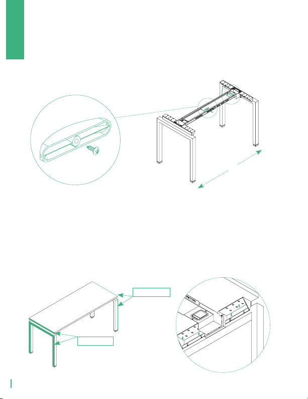
Using 2 wood screws, secure the flat plates to the edge of the
main surface with half of the plate extended over the edge of
the surface. Using 4 wood screws, secure the support bar to the
underside of the surface centered between the flat plates.
Assemble the return surface by securing BL24 leg to the underside
of the laminate surface with wood screws.
Align return surface with the back of the main desk and secure the
flat plates and support bar with wood screws into the underside of
the surface.
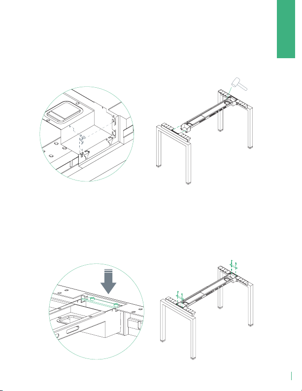
Tighten the screw on the main profile beam.
5 |SECURE HARDWARE AND ASSEMBLE RETURN
6 |ATTACH RETURN TO MAIN DESK
L-SHAPE
GROVE
4