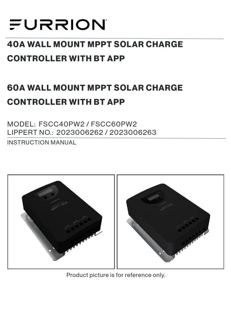
Furrion NET-ZERO FSCC30PW-BL User manual

PPT Solar Charge Controller
Régulateur de charge solaire PPT
Controlador de carga solar PPT
Picture shown here is for reference only.
L'image montrée ici est pour référence seulement.
La imagen que se muestra aquí es sólo para referencia.
Model/Modèle/Modelo:
FSCC30PW-BL / FSCC60PW-BL / FSCC60PWM-BL
Instruction Manual
Manuel d'instructions
Manual de instrucciones

1
Welcome
nglish
Thank you and congratulations for purchasing the Furrion® MPPT solar charge controller.
Before operating your new product, please read these instructions carefully. This instruction
manual contains information for safe use, installation and maintenance of the product.
Please keep this instruction manual in a safe place for future reference. This will ensure safe
use and reduce the risk of injury. Be sure to pass on this manual to new owners of this product.
The manufacturer does not accept responsibility for any damages due to not observing these
instructions.
If you have any further questions regarding our products, please contact us at
supportfurrion.com

2
Contents
nglish
Welcome ............................................................................................1
Contents ............................................................................................2
Important Safety Instructions ............................................................3
General Safety Precautions ....................................................................................3
Charge Controller Safety ........................................................................................3
Battery Safety ..........................................................................................................3
About your Product ............................................................................4
General Information ................................................................................................4
Key Features ...........................................................................................................4
Product Overview ..............................................................................5
Optional Components..............................................................................................5
aximum Power Point Tracking ( PPT) ............................................6
Charging Stages.................................................................................7
Installation ........................................................................................8
What’s in the Box ....................................................................................................8
Solar Charger Mounting Bracket Installation (if included) ....................................8
MPPT Solar Charger Controller Installation ..........................................................8
PV Array Requirements ...........................................................................................11
Wire Size ..................................................................................................................11
Operation ...........................................................................................12
Protection ..........................................................................................13
Care and aintenance .......................................................................14
Specifications ....................................................................................15
Troubleshooting .................................................................................17
Warranty ............................................................................................18

3
Important Safety Instructions
nglish
I PORTANT: SAVE THESE INSTRUCTIONS–
This manual contains important instructions
for Models FSCC30PW-BL and FSCC60PW-
BL that shall be followed during installation
and maintenance of the charge controller.
The following symbols are used throughout
the manual to indicate potentially dangerous
conditions or important safety information.
WARNING
Indicates a potentially dangerous condition. Use
extreme caution when performing this task.
CAUTION
Indicates a critical procedure for safe and
proper operation of the controller.
NOTE: Indicates a procedure or function that
is important to the safe and proper operation
of the controller.
General Safety Precautions
Read carefully all the instructions and
warnings in the manual before installation.
ƔNo user serviceable component inside
controller. DO NOT disassemble or
attempt to repair the controller.
ƔMount the controller indoors. Prevent
exposure to the elements and do not
allow water to enter the controller.
ƔInstall the controller in well ventilated
places, the controller may become hot
during operation.
ƔSuggested to install appropriate external
fuses/breakers.
ƔMake sure to switch off all connections
with PV array and the fuse/breakers close
to battery before controller installation
and adjustment.
ƔPower connections must remain tight
to avoid excessive heating from a loose
connection.
Charge Controller Safety
ƔNEVER connect the solar panel array to
the controller without a battery. Battery
must be connected to the controller first.
ƔEnsure input voltage does not exceed 130
VDC (FSCC60PW-BL) /70VDC(FSCC30PW-
BL) to prevent permanent damage. Use
the Open Circuit (Voc) to make sure the
voltage does not exceed this value when
connecting panels together.
Battery Safety
ƔUse sealed lead-acid, flooded and gel
batteries which must be deep cycle or
LiFePo4 Lithium battery.
ƔExplosive battery gases may be present
while charging. Be certain there is
enough ventilation to release the gases.
ƔBe careful when working with large lead
acid batteries. Wear eye protection and
have fresh water available in case there is
contact with the battery acid.
ƔCarefully read battery manuals before
operation.
ƔDo NOT let the positive (+) and negative (-)
terminals of the battery touch each other.
ƔRecycle battery when it is replaced.

4
About your Product
nglish
General Information
Through the use of MPPT technology,
the Furrion MPPT series can increase
charge current by up to 30% compared to
conventional PWM controllers. Furrion’s
sophisticated three stage charge control
system can be configured to optimize charge
parameters to precise battery requirements.
The unit is fully protected against voltage
transients, over temperature, reverse
battery and reverse PV connections. Fully
automatic temperature compensation of
charge voltage is available to further improve
charge control and battery performance. The
sensor element is environmentally sealed
and encapsulated into a connection lug which
directly connects to the battery terminals.
Furrion MPPT charge controller with RV-C
communication bus interface and RV-C CAN
bus communication protocol is available to
meet the communication requirements in RV.
Key Features
ƔCompatible with 12V or 24V battery
system.
ƔAdvanced maximum power point tracking
technology to optimize the use of the PV
system. High tracking efficiency of 99%.
ƔHigh open circuit voltage of PV input.
ƔBattery is active in low voltage state.
ƔSealed, AGM and LiFePO4 Lithium battery
option.
ƔECO mode, automatic recognition of day
and night.
ƔTemperature compensation and
corrective charging.
ƔRV-C CAN bus communication protocol.
ƔReverse protection: Any combination
of solar modules and batteries can be
made without causing damage to any
component.
ƔElectronic protection: overcharging, over
temperature, over PV input power.
ƔEasy to assemble: simply slide the
controller into the Furrion Solar Charger
Mounting Bracket (model FSCC60PWM
not included).

5
Product Overview
nglish
Mounting Hole
Cooling Grid
Charge mode
indicator LED
Battery selection
button
Optional Components
The FSCC30PW-BL, FSCC60PW-BL is shipped by itself, without any additional components.
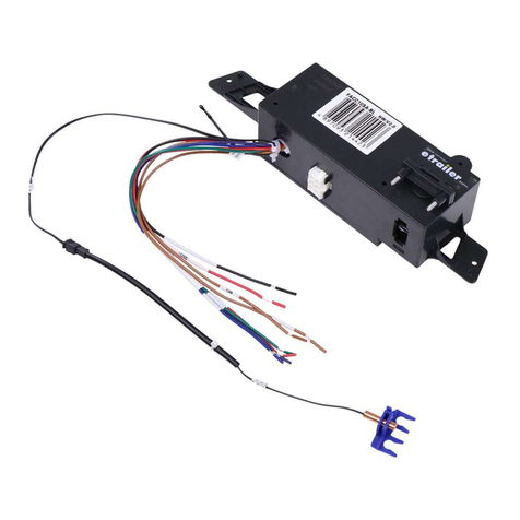
Optional components that require a separate purchase: Temperature sensor 5m (C-FSCC60PW-A01)
or 10m (C-FSCC60PW-A02), the Solar Charger Wall Mount Bracket (FSCC60PWM-BL).

6
Maximum Power Point Tracking (MPPT)
nglish
The Furrion solar MPPT Controller can charge up to 30% more compared to traditional PWM
charge controllers.
Upper curve:
Output current (I) of a solar panel as function of output voltage (V). The maximum power point
(MPP) is the point Pmax along the curve were the product I x V reaches its peak.
Imp
Short
circuit
current
I
Pmax
Lower curve:
Output power P = I x V as function of output voltage. When using a PWM (not MPPT) controller
the output voltage of the solar panel will be nearly equal to the voltage of the battery, and will
be lower than Vmp.
mp dc
P
Pmax

7
Charging Stages
nglish
Bulk stage
During this stage the MPPT controller delivers the maximum current to rapidly recharge the
batteries. When the battery voltage reaches the absorption voltage setting, the MPPT controller
activates the next stage (absorption).
Absorption stage
During this stage, the MPPT controller switches to the constant voltage mode, where the
absorption voltage is applied to the battery. When the charge current decreases to the float
transition current setting, the battery is fully charged and the MPPT controller switches to the
float stage. The default time for float stage is 120 minutes.
Float stage
During this stage, the float voltage is applied to the battery to maintain it in a fully charged
state. When battery voltage drops below the recharge setting voltage a new bulk cycle will be
triggered.
ulk
urrent
(Amperes)
Voltage
(Volts)
Absorption Float

8
Installation
nglish
What’s in the Box
Make sure you have all the following items
included in the packaging. If any item is
damaged or missing, contact your dealer.
−MPPT Solar charge controller x 1
−Instruction Manual x 1
−Warranty Card x 1
−Solar Charger Mounting Bracket x 1
−Flat head drilling screw (ST4.2 19mm)
x 4
For FSCC30PWB-BL & FSCC60PWB-BL only.
CAUTION
The controller requires at least 6" of
clearance above and below for proper air
flow. Ventilation is highly recommended if
mounted in an enclosure.
WARNING:
Risk of explosion! Never install the controller
in a sealed enclosure with flooded batteries!
Do not install in a confined area where
battery gas can accumulate.
WARNING:
Risk of electric shock! Exercise caution
when handling solar wiring. The solar PV
array can produce open-circuit voltages in
excess of 100V when in sunlight.
WARNING:
Risk of electric shock!
Make sure that all the power is turned off
before installation and operation.
Solar Charger Mounting Bracket
Installation (if included)
Refer to separate Solar Charger Mounting
Bracket installation manual included in the
packaging to install it.
MPPT Solar Charger Controller
Installation
1. Insert the MPPT controller into the Solar
Charger Mounting Bracket (FSCC60PWM-
BL). (Figure 1)
Fig. 1

9
Installation
nglish
. Affix MPPT controller to the wall with 4
mounting screws (not included). (Figure 2)
Fig. 2
3. Loosen the ground lug screw located on
the left side of the mounting bracket.
Insert a 10AWG copper wire from this lug
to chassis ground. Tighten the ground
lug screw securely. The suggested torque
force should be 5lbs-inch. (Figure 3)
Ground lug
10AWG
copper wire
Fig. 3
4. Plug the temperature sensor connector
to the temperature sensor port (if
applicable). (Figure 4)
Temperature sensor
Fig. 4
5. Plug the RV-C connector to the MPPT
controller. (Figure 5)
RV-C connector
Fig. 5

10
Installation
nglish
6. Turn on the terminal resistance switch
if communication network is needed.
(Figure 6)
Switch
Fig. 6
7. Turn on the disconnect switch for battery.
(Figure 7)
8. Turn on the disconnect switch for PV
array. (Figure 7)
Battery
+
+ -
-
Switch
Fuse
PV
array
Switch
Fuse
ooftop Solar
Electrical Box
Fig. 7

11
Installation
nglish
PV Array Requirements
The MPPT controller will limit battery
charging current to the Rated Charge
Current. Although the controller can harvest
the rated power of controller, the PV array
size can be as high as Pmax (Pmax=IBat
VBat), the acceptable PV array size as below:
odel FSCC30PW-BL FSCC60PW-BL
aximum PV
short circuit
current
20A 40A
aximum PV
array 300W 600W
aximum PV
open circuit
voltage
70V 135V
NOTE:
ƔThe array Isc (Short Circuit Current) must
not exceed the rated charge current of
controller.
ƔThe Voc of PV array could be affected
by ambient temperature, causing
fluctuation. Before connecting PV array,
please ensure the Voc at any temperature
does not exceed the maximum open-
circuit voltage of the controller.
ƔThe Isc of PV array should not exceed
the maximum short circuit current of the
controller.
ƔThe PV array is suggested to be
connected by series.
WARNING
Controller will be damaged when the open
circuit voltage of PV array reverse polarity
and the actual operation power of the PV
array is greater than the rated open circuit
voltage and rated input power.
Wire Size
The wiring and installation methods must
conform to all national and local electrical
code requirements.
PV Wire Size
Since the PV outputs can vary due to the
array connection method, the minimum
wire size must be in accordance with the
maximum array short-circuit current. The PV
array is suggested to be connected by series.
Please use PV Photovoltaic wire, the
reference size as below:
PV short
circuit current Wire Gauge aximum
Wire Length
10A 12AWG 30FT
NOTE: The wire size is only for reference.
If there is a long distance between the PV
array and the controller, larger wires can be
used to reduce the voltage drop and improve
performance.
Battery Wire Size
The battery wire size must conform to the
rated current, the reference size as below:
odel FSCC30PW-BL FSCC60PW-BL
aximum
charge
current
25A 50A
Wire Gauge 10AWG 6AWG
aximum
Wire Length 15FT 15FT
NOTE: The wire size is only for reference.
If there is a long distance between the
controller and the battery, larger wires can
be used to reduce the voltage drop and
improve performance.

12
Operation
nglish
Operation
1AGM battery mode indicator, this is a yellow LED, the LED will light when the
MPPT solar controller is in AGM battery charge mode.
2SEALED battery mode indicator, this is a yellow LED, the LED will light when the
MPPT solar controller is in sealed lead acid battery charge mode.
3LITHIUM battery mode indicator, this is a green LED, the LED will light when the
MPPT solar controller is in LiFePO4 lithium battery charge mode.
4Charge and fault indicator, this is a bicolor LED, the LED will be red if there is
a fault or if no battery is connected; the LED will be flashing green when the
MPPT solar charge controller is charging the battery, the LED will be solid
green when the battery is full or in float charge stage.
5This is a button, short press the button to activate the controller from ECO
mode, long press the button for 2 seconds to select the different battery modes.
Factory default : long press the button for 5 seconds.
234 5
1

13
Protection
PV Over Current
The controller will limit charge power in rated charge power. An over-sized PV array will not
operate at maximum power point.
PV Short Circuit
When PV short circuit occurs, the controller will stop charging. Clear it to resume normal
operation.
PV Reverse Polarity
Full protection against PV reverse polarity, no damage to the controller. Correct the reversely
connected wires to resume normal operation.
Battery Reverse Polarity
Full protection against battery reverse polarity, no damage to the controller will result. Correct
the reversely connected wires to resume normal operation.
Battery Over voltage
When battery voltage reaches the voltage set point of Over Voltage Disconnect, the controller
will stop charging the battery to protect the battery.
Damaged Remote Temperature Sensor
If the temperature sensor is short-circuited or damaged, the controller charge at the default
temperature 25˚C to prevent the battery from being damaged by overcharging.
Controller Overheating
The MPPT controller will cut off its output while the temperature inside is too high, and it will
restart when the inside temperature is cooling down.
nglish

14
Care and Maintenance
nglish
The following inspections and maintenance tasks are recommmended at least twice per year
for best performance:
ƔMake sure controller is firmly installed in a clean and dry location.
ƔMake sure there is open air-flow around the controller.
ƔClean any dirt or dust that has accumulated on the cooling grid and fan grid.
ƔCheck all of the exposed wires to make sure insulation is not damaged from serious
solarization, frictional wear, dryness, insects or pests etc. Repair or replace wires if
necessary.
ƔTighten all of the terminals. Inspect for loose, broken, or burnt wire connections.
ƔPay attention to any troubleshooting or error indication.Take corrective action if necessary.
ƔConfirm that all system components ground connections are tight and correct.
ƔConfirm that all the terminals have no corrosion, no insulation damage, no signs of high
temperature damage (discolored or burnt).
ƔTighten terminal screws to the suggested torque.
ƔClear all dirt, nesting insects and corrosion from terminals.
ƔConfirm that lightning arrester is in good condition. Replace if necessary.
WARNING
Risk of electric shock!
Make sure that all the power is turned off before above inspection and maintenance tasks,
and then follow the corresponding inspections and operations.

15
Specifications
nglish
Specifications
ITE FSCC30PW-BL FSCC60PW-BL
Battery System Voltage 12V/24V 12V/24V
ax. PV Power (Pmax) 300W 600W
ax. PV open circuit Voltage (VOC)
70V 135V
PPT efficiency ≥99% ≥99%
ECO mode draw current <1mA <1mA
in. Battery Voltage for Charging 3V 3V
ax. PPT Charging Current 25A 50A
Charging ode (three charging
stage)
Bulk voltage charging,
Absorption charging and Float
charging
Bulk voltage charging,
Absorption charging and Float
charging
Different battery mode option AGM, LiFePO4, Sealed lead
acid
AGM, LiFePO4, Sealed lead
acid
Bulk voltage
Sealed lead acid:14.4v/28.8v
AGM:14.6v/29.2v
Lithium:14.6v/29.2v
Sealed lead acid:14.4v/28.8v
AGM:14.6v/29.2v
Lithium:14.6v/29.2v
Float voltage
Sealed lead acid:13.2v/26.4v
AGM:13.4v/26.8v
Lithium:13.6v/27.2v
Sealed lead acid:13.2v/26.4v
AGM:13.4v/26.8v
Lithium:13.6v/27.2v
LED indicator YES YES
Automatic Detection for 12v/24v
Battery YES YES
Automatic Temperature
Compensation YES YES
Battery Over Charging Protection YES YES
PV Reverse Protection YES YES
Battery Reverse Protection YES YES
Over Temperature Protection YES YES
Grounding Common Negative Common Negative
Communication Port 4Pin RV-C Socket 4Pin RV-C Socket
ODEL NU BER

16
Specifications
nglish
Specifications
ITE FSCC30PW-BL FSCC60PW-BL
Certificate
Listed to CSA, Compliance
to UL1741 and CSA C22.2
No.107.1-16
Listed to CSA, Compliance
to UL1741 and CSA C22.2
No.107.1-16
E C Meet FCC Part 15 Class B and
ICES-003
Meet FCC Part 15 Class B and
ICES-003
Operating Temperature Range -20°C~40°C/ -4°F~104°F -20°C~40°C/ -4°F~104°F
Storage Temperature Range -30°C~+70°C/-22°F~+158°F,
10~95% RH
-30°C~+70°C/-22°F~+158°F,
10~95% RH
Dimensions 225 220.6 68mm 275 220.6 68mm
Net weight 1.85kg 2.3kg
Note: When a battery temperature sensor is installed, the controller will increase or decrease
battery charging voltage depending on the temperature of the battery, optimizing the charge to
the battery and maintaining optimal battery performance.
ODEL NU BER

17
Troubleshooting
nglish
FAULT POSSIBLE REASONS TROUBLESHOOTING
No output voltage No solar input or solar input
voltage too low
Check the if the switch for the solar
input was turned on
Fault LED be red
Battery polarity reverse Check the connection of the battery,
correct the connection if necessary
PV reverse Check the connection of the PV input,
correct the connection if necessary
Battery over charge Check if the battery is good, replace
the battery if necessary
Battery not fully charged
Too much load connects to the
battery Remove the loads
Battery temperature too low Use the battery temperature sensor
Wrong battery type setting Choose the correct battery type by long
press the button
Battery wire too small Use the larger gauge wire for the
battery to reduce the voltage drops
Battery not charged
Too much load connects to the
battery Remove the loads
Battery damaged Check the battery, replace the battery
if necessary

18
nglish
Warranty
FURRION WARRANTS FOR A PERIOD OF 1 YEAR FROM DATE OF RETAIL PURCHASE BY THE
ORIGINAL END-USE PURCHASER, THAT THIS PRODUCT, WHEN DELIVERED TO YOU IN NEW
CONDITION, IN ORIGINAL PACKAGING, FROM A FURRION AUTHORIZED RESELLER AND USED
IN NORMAL CONDITIONS, IS FREE FROM ANY DEFECTS IN MANUFACTURING, MATERIALS,
AND WORKMANSHIP. IN CASE OF SUCH DEFECT, FURRION SHALL REPLACE OR REPAIR THE
PRODUCT AT NO CHARGE TO YOU. THIS WARRANTY DOES NOT COVER: PRODUCTS WHERE
THE ORIGINAL SERIAL NUMBERS HAVE BEEN REMOVED, ALTERED OR CANNOT READILY
BE DETERMINED; DAMAGE OR LOSS CAUSED BY ACCIDENT, MISUSE, ABUSE, NEGLECT,
PRODUCT MODIFICATION, FAILURE TO FOLLOW INSTRUCTIONS IN INSTRUCTION MANUAL,
COMMERCIAL OR INDUSTRIAL USE; DAMAGE OR LOSS CAUSED TO THE DECORATIVE
SURFACE OF PRODUCT; TO ANY DATA, SOFTWARE OR INFORMATION; AND NORMAL WEAR
AND TEAR. THIS WARRANTY ONLY PROTECTS THE ORIGINAL END-USER (“YOU”) AND
IS NOT TRANSFERABLE; ANY ATTEMPT TO TRANSFER THIS WARRANTY SHALL MAKE IT
IMMEDIATELY VOID. THIS WARRANTY IS ONLY VALID IN THE COUNTRY OF PURCHASE.
THIS WARRANTY AND REMEDIES SET FORTH ABOVE ARE EXCLUSIVE AND IN LIEU OF ALL
OTHER WARRANTIES, REMEDIES AND CONDITIONS, WHETHER ORAL OR WRITTEN, EXPRESS
OR IMPLIED. FURRION SPECIFICALLY DISCLAIMS ANY AND ALL IMPLIED WARRANTIES,
INCLUDING, WITHOUT LIMITATION, WARRANTIES OF MERCHANTABILITY AND FITNESS FOR
A PARTICULAR PURPOSE. IF FURRION CANNOT LAWFULLY DISCLAIM IMPLIED WARRANTIES
UNDER THIS LIMITED WARRANTY, ALL SUCH WARRANTIES, INCLUDING WARRANTIES OF
MERCHANTABILITY AND FITNESS FOR A PARTICULAR PURPOSE ARE LIMITED IN DURATION
TO THE DURATION OF THIS WARRANTY.
No Furrion reseller, agent, or employee is authorized to make any modification, extension, or
addition to this warranty.
FURRION IS NOT RESPONSIBLE FOR DIRECT, INDIRECT, SPECIAL, INCIDENTAL OR
CONSEQUENTIAL DAMAGES RESULTING FROM ANY BREACH OF WARRANTY OR CONDITION,
OR UNDER ANY OTHER LEGAL THEORY, INCLUDING BUT NOT LIMITED TO LOST PROFITS,
DOWNTIME, GOODWILL, DAMAGE TO OR REPLACEMENT OF ANY EQUIPMENT OR PROPERTY,
ANY COSTS OF RECOVERING, REPROGRAMMING, OR REPRODUCING ANY PROGRAM OR DATA
STORED IN OR USED WITH FURRION PRODUCTS. FURRION’S TOTAL LIABILITY IS LIMITED
TO THE REPAIR OR REPLACEMENT OF THIS PRODUCT PURSUANT TO THE TERMS OF THIS
WARRANTY.
SOME STATES DO NOT ALLOW THE EXCLUSION OR LIMITATION OF INCIDENTAL OR
CONSEQUENTIAL DAMAGES OR EXCLUSIONS OR LIMITATIONS ON THE DURATION OF IMPLIED
WARRANTIES OR CONDITIONS, SO THE ABOVE LIMITATIONS OR EXCLUSIONS MAY NOT APPLY
TO YOU. THIS WARRANTY GIVES YOU SPECIFIC LEGAL RIGHTS, AND YOU MAY ALSO HAVE
OTHER RIGHTS THAT VARY BY STATE OR (WHERE APPLICABLE IN THE COUNTRIES WHERE
FURRION HAS NON-US/CANADIAN AUTHORIZED DEALERS) COUNTRY. NO ACTION OR CLAIM
TO ENFORCE THIS WARRANTY SHALL BE COMMENCED AFTER THE EXPIRATION OF THE
WARRANTY PERIOD.
Keep your receipt, delivery slip, or other appropriate payment record to establish the warranty
period. Service under this warranty must be obtained by contacting Furrion at
Product features or specifications as described or illustrated are subject to change without
notice.

19
Bienvenue
French
Merci d'avoir acheté ce Furrion® régulateur de charge solaire MPPT. Avant utiliser votre nouvel
appareil, veuillez lire ces consignes attentivement. Le présent guide d’utilisation contient des
informations permettant l’utilisation, l’installation et l’entretien en toute sécurité de l’appareil.
Veuillez conserver le présent guide d’utilisation en lieu sûr pour vous y référer ultérieurement,
afin d’assurer votre sécurité et de réduire les risques de blessure. Veuillez aussi remettre le
présent manuel à tout nouveau propriétaire de cet appareil.
Le fabricant décline toute responsabilité en cas de dommages dus au non-respect des
présentes consignes.
Si vous avez des questions sur nos produits, veuillez nous contacter : [email protected]
This manual suits for next models
2
Table of contents
Languages:
Other Furrion Controllers manuals
Popular Controllers manuals by other brands

Netafim
Netafim AlphaDisc CLD quick guide

Hanyoung
Hanyoung TPR-2N instruction manual

ATTO Technology
ATTO Technology ATTO XstreamCORE FC 7500 Installation and operation manual

Zaber Technologies Inc.
Zaber Technologies Inc. X-MCB1 Series user manual

BIFFI
BIFFI GIGS 0.3 Use and maintenance manual

Elko
Elko RFWB-20/G manual

turck
turck FEN20-4DIP-4DXP Getting started guide

Absima
Absima WP1040-BRUSHED user manual

Merlin
Merlin 58177 quick start guide

Extron electronics
Extron electronics MEDIALINK MLC 206 Setup guide

Synapse
Synapse DIM10-087-06-FW installation guide

RenewAire
RenewAire HE Series Installation, operation and maintenance manual