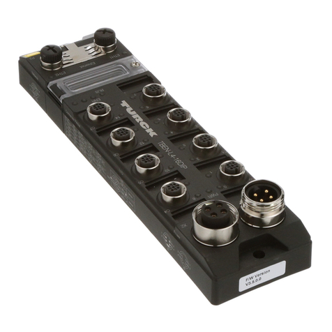
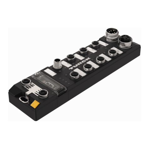
turck FEN20-4DIP-4DXP User manual

Your Global Automation Partner
Getting Started Guide
FEN20-…
Startup

2 Hans Turck GmbH & Co. KG | T +49 208 4952-0 | F +49 208 4952-264 | more@turck.com | www.turck.com

3
V01.00 | 2018/08
1 General Information 4
1.1 About these Instructions 4
1.2 Explanation of Symbols Used 4
1.3 Additional Documents 4
1.4 Feedback about these Instructions 4
2 Notes on the Product 5
2.1 Product Identication 5
2.2 Manufacturer and Service 5
3 FEN20 Product Family 6
3.1 Denition of Terms 6
4 FEN20 IP Address Setup 8
4.1 FEN20-4DIP-4DXP 8
4.2 Downloading Turck Service Tool 8
4.3 Service Tool Features 9
4.3.1 Assigning an IP Address using Turck Service Tool 9
4.4 Assigning an IP Address using Rockwell BOOTP/DHCP 10
4.5 FEN20-16DXP 12
4.5.1 Modes of Operation 12
5 EtherNet/IP™ Conguration (Rockwell) 15
5.1 Turck Catalog Files 15
5.2 Conguration with Catalog File 16
5.3 Conguration with EDS File 18
6 PROFINET Conguration 21
6.1 GE Procy Machine Edition Setup 21
6.1.1 Create New GE Project 21
6.1.2 Add the FEN20 Device 24
6.1.3 Assign FEN20 Name and IP Address 25
6.1.4 Installing GSD / GSDML Files in the Hardware Conguration 26
6.1.5 Adding a PROFINET Device onto the Network. 27
7 Modbus TCP Conguration 30
7.1 Create TX500 Modbus TCP Master Project 31
7.1.1 Add Ethernet Adapter 32
7.1.2 Add Modbus Master 34
7.1.3 Add Modbus TCP Slave 37
7.1.4 Congure FEN20 IO Data Map 38
Table of Contents

4 Hans Turck GmbH & Co. KG | T +49 208 4952-0 | F +49 208 4952-264 | more@turck.com | www.turck.com
General Information
1 General Information
1.1 About these Instructions
These operating instructions describe the structure, functions and the use of the product and
will help you to operate the product as intended. Read these instructions carefully before using
the product. This is to avoid possible damage to persons, property or the device. Retain the in-
structions for future use during the service life of the product. If the product is passed on, pass
on these instructions as well.
1.2 Target groups
This document is written for specially trained personnel, and must be read carefully by anyone
who is responsible for the mounting, commissioning, operation, maintenance, disassembly or
disposal of the device.
1.3 Explanation of Symbols Used
The following symbols are used in these instructions
DANGER
DANGER indicates an immediately dangerous situation, with high risk, the death or
severe injury, if not avoided.
WARNING
WARNING indicates a potentially dangerous situation with medium risk, the death or
severe injury, if not avoided.
ATTENTION
ATTENTION indicates a situation that may lead to property damage, if it is not avoided.
NOTE
In NOTES you find tips, recommendations and important information. The notes facili-
tate work, provide more information on specific actions and help to avoid overtime by
not following the correct procedure.
CALL TO ACTION
This symbol identifies steps that the user has to perform.
RESULTS OF ACTION
This symbol identifies relevant results of steps
1.4 Additional Documents
The following additional documents are available online at www.turck.com:
■Data sheets
1.5 Feedback about these Instructions
We make every effort to ensure that these instructions are as informative and as clear as pos-
sible. If you have any suggestions for improving the design or if some information is missing in

5
V01.00 | 2018/08
2 Notes on the Product
2.1 Product Identication
The following user manual describes common features and setup of the FEN20 product family:
■IP address setup
■EtherNet/IP™ configuration example
■PROFINET configuration example
■Modbus TCP configuration example
2.2 Manufacturer and Service
Hans Turck GmbH & Co. KG
Witzlebenstraße 7
45472 Muelheim an der Ruhr
Germany
Turck supports you with your projects, from initial analysis to the commissioning of your ap-
plication. The Turck product database contains software tools for programming, configuration
or commissioning, data sheets and CAD files in numerous export formats. You can access the
product database at the following address: www.turck.de/products
Should you have any further questions, please contact the sales and service team in Germany
under the following telephone numbers:
Sales: +49 208 4952-380
Technology: +49 208 4952-390
Internet: www.turck.com/support
Outside Germany, please contact your local Turck representative.

6 Hans Turck GmbH & Co. KG | T +49 208 4952-0 | F +49 208 4952-264 | more@turck.com | www.turck.com
FEN20 Product Family
3 FEN20 Product Family
The common features and operating procedures, which are described in this guide, may be ap-
plied to every released FEN20 device, see the following table and„3.1 Definition of Terms“.
Article IP Input description Output description EtherNet/IP™™ Ad-
vanced
features
Address setup
Number of inputs
DIN rail mount
Input type
Signal type
Short circuit protection
Number of outputs
Output type
Signal type
Maximum output load
Short circuit protection
Ethernet ports
Conguration Assembly
DLR
QC
ACD
FLC
BEEP
FEN20-4DIP-4DXP S 8 - DI PNP ✓8 DO PNP 0.5A - 2 ✓✓✓✓✓✓
FEN20-4DIP-4DXP-DIN S 8 ✓DI PNP - 8 DO PNP 0.5A ✓2✓✓✓✓✓✓
FEN20-4DIN-4DXN S 8 - DI NPN ✓8 DO NPN 0.5A ✓2✓✓✓✓✓✓
FEN20-4DIN-4DXN-DIN S 8 ✓DI NPN ✓8 DO NPN 0.5A ✓2✓✓✓✓✓✓
FEN20-EN1 S 8 - R PNP - - - - - ✓2✓✓✓✓- -
FEN20-EN1-DIN S 8 ✓R PNP - - - - - ✓2✓✓✓✓- -
FEN20-16DXP SH 16 - DI PNP - 16 DO PNP 0.5A ✓2✓✓✓✓- -
3.1 Denition of Terms
■Address setup
S Software setup
SH Software & Hardware setup via rotary switches
■IO type
DI Discrete input
DO Discrete output
R Router function
AI Analog input
AO Analog output
■Signal type
PNP Sourcing
NPN Sinking
■EtherNet/IP™
ūConfiguration assembly – enables passing configuration data during ForwardOpen
ūDLR Device Level Ring
ūQC QuickConnect
ūADC Address Conflict Detection
■Advanced features
ūFLC Field Logic Controller
FEN20 can be converted into a simple Field Logic Controller (i.e. PLC) that can execute a
stand-alone application or become a distributed control component of the EtherNet/IP™,

7
V01.00 | 2018/08
Modbus TCP or PROFINET based control system.
FLC solutions by Turck are made possible using ARGEE (A Really Great Engineering Envi-
ronment), a web-based programming environment that allows users to set conditions and
actions directly at the field level. By utilizing HTML5, Turck provides a complete engineering
environment for users to write, run, simulate, debug, and monitor code, all without requi-
ring the use of a PLC.
ūBEEP Backplane Ethernet Extension Protocol
BEEP is a new technology feature of many Turck Multiprotocol digital block I/O modules.
BEEP allows a network of up to 33 devices (1 Master + 32 Slaves) or 480 bytes of data, to
appear to the PLC as a single device on a single connection using a single IP Address of the
Master.
NOTE
BEEP is supported by the following FEN20 devices that have firmware revision:
■V 3.3.4.0 FEN20-4DIP-4DXP, FEN20-4DIN-4DXN
■In progress FEN20-16DXP
■not supported FEN20-EN1, FEN20-EN1-DIN
Refer to“ARGEE Reference Manual” for further information on FLC.
Refer to“BEEP Reference Manual” for further information on BEEP.

8 Hans Turck GmbH & Co. KG | T +49 208 4952-0 | F +49 208 4952-264 | more@turck.com | www.turck.com
FEN20 IP Address Setup
4 FEN20 IP Address Setup
All FEN20 devices support software setup of the IP address using either “Turck Service Tool” or
BOOTP/DHCP server. Additionally,
■FEN20-16DXP has rotary switches capable of setting the IP address.
■FEN20-4DIP-4DXP and FEN20-4DIN-4DXN stations do not have rotary switches capable of
setting the IP address.
4.1 FEN20-4DIP-4DXP
Users should set the IP address using either“Turck Service Tool” or any other IP address server
such as BOOTP/DHCP utility, to set, modify or reset the IP address of the device.
The device out of box IP address setup is:
■IP address: 192.168.1.254
■Netmask: 255.255.255.0
■Gateway: 0.0.0.0
Mode of operation:
■PGM Programmable
■DHCP Dynamic Host Configuration Protocol
NOTE
In the PGM mode the device will reference the previous IP address at power-up, which
was assigned to the device prior to shut down. Use “Turck Service Tool” for the IP ad-
dress management.
4.2 Downloading Turck Service Tool
The Turck Service Tool can be downloaded from the Turck Website using the following link:
■http://pdb2.Turck.de/us/DE/products/0000001a000293cb0002003a

9
V01.00 | 2018/08
4.3 Service Tool Features
The Service tool displays the assigned IP addresses of devices on the network:
Overview of Features
■F5 – Network Search function is used to discover Turck devices connected to the same physi-
cal network segment
■F2 – Change device IP address when device is set to PGM or PGM_DHCP mode, or assign
device a PROFINET name
■F3 – Wink command - flashes BUS LED of the highlighted device
■F4 – Action button - used to reset the device to the factory default setting
■Clipboard – copies selected connection
■Language – Selects between English and German text
■Expert View - Enables / disables advanced functions
■F6 – DHCP server
■F7 – EtherNet/IP™ configuration page
■F8 – Device ARGEE info
4.3.1 Assigning an IP Address using Turck Service Tool
Click F5 – Search network
Highlight the device to be assigned / changed an IP address
Abb. 1:
Click F2 – Enter the IP address, Netmask and Gateway addresses.

10 Hans Turck GmbH & Co. KG | T +49 208 4952-0 | F +49 208 4952-264 | more@turck.com | www.turck.com
FEN20 IP Address Setup
Complete setup by clicking button
The Service tool immediately shows newly assigned IP address. The device Webserver may be
initiated by clicking on the IP address hyperlink if the address is on the same subnet as a PC
that runs the Service too.
NOTE
“0.0.0.0” at IP address, Netmask and Gateway, indicates that the device came up
with the factory default setup and that DHCP client is active, requesting IP address
assignment.
4.4 Assigning an IP Address using Rockwell BOOTP/DHCP
Search Rockwell Software directory for BOOTP/DHCP server tool:
Start DHCP tool and click on the MAC address of the device which needs and IP address
Enter IP address and click OK

11
V01.00 | 2018/08
The device is successfully assigned IP address when it appears in the“IP Address” column

12 Hans Turck GmbH & Co. KG | T +49 208 4952-0 | F +49 208 4952-264 | more@turck.com | www.turck.com
FEN20 IP Address Setup
4.5 FEN20-16DXP
Three rotary switches of the FEN20-16DXP provide various modes of operation, as seen
below.
4.5.1 Modes of Operation
Based on the position of the switches, the device performs the following operation:
■000 Restore IP address
■300 BOOTP mode client
■400 DHCP mode client
■500 PGM programmable mode
■600 PGM-DHCP mode
■700 PROFINET mode
■900 Device Recovery Mode (F_reset)
■1-254 Static IP address
NOTE
The general rule of handling rotary switches when selecting mode of operation is:
■Set the rotary switches to the desired position
■Cycle power to the station
■Proceed with intended operation as explained hereafter
Restore Mode (000)
The Restore IP address mode restores the IP address to the default value. When switches are
set at 000, the device is capable to:
■Respond to PING command,
■Respond to Turck Service tool
■Run device Webserver
The device cannot be connected to a PLC and it does not respond to any connection request.
Default IP Address
The factory default setup when switches are set to “000”position:
■IP address 192.168.1.254
■Subnet 255.255.255.0
■Gateway 0.0.0.0

13
V01.00 | 2018/08
BOOTP/DHCP Mode (300/400)
■Assigns an IP address using the BOOTP/DHCP server respectively.
After an IP address is assigned, it is temporarily stored in the device. In order to permanently
store the IP address, set the rotary switches to either:
■001-253 which affects the last octet of the device IP address
■500 programmable position
Then cycle power to the device.
PGM Mode (500)
Launch the Turck Service Tool
Select F5 – search network
Under “Mode”verify the device reads PGM
Select F2 – change IP address
Enter desired value
Click “Set in device”

14 Hans Turck GmbH & Co. KG | T +49 208 4952-0 | F +49 208 4952-264 | more@turck.com | www.turck.com
FEN20 IP Address Setup
PGM-DHCP mode (600)
PGM-DHCP mode is a combination of the DHCP (400) and PGM (500) modes.
The device, when initially powered with switches set to 600, acts as DHCP client. It requests
assignment of an IP address. After the IP address is assigned, the device disables DHCP and
switches to PGM mode. Switches may be left in 600 position.
Upon power cycle, the device retains the last known IP address.
To reset PGM-DHCP mode, set rotary switches to 000 and cycle power
PROFINET mode (700)
Allows a PROFINET server to assign a PROFINET name and IP address to the device. The Turck
service tool may be used to assign device name and IP address.
RECOVERY Mode (900)
When the rotary switches are set to the RECOVERY mode (900), the device resets all device
resources to factory default values, including configuration parameters and IP address.
Set rotary switches to 900, cycle the power and wait 10 seconds
Set rotary switches to any other position and then cycle power.

15
V01.00 | 2018/08
5 EtherNet/IP™ Conguration (Rockwell)
It is assumed that there is working knowledge of RS Logix Desinger from Rockwell.
The FEN20 is configured on the EtherNet/IP™ network using either:
■Generic device profile or
■EDS file
The single generic device profile is available with the Logix5000 controllers. The collection of
the generic device profiles of the Turck devices is called a “Turck Catalog File”.
5.1 Turck Catalog Files
Turck devices are assigned pre-defined configurations using the generic device profile. The
device configuration contains following information, as an example:
The collection of the predefined configurations is saved as an L5K file and called the catalog
file.
There are several different catalog files:
■Turck_BLOCK_STATIONS , contains all block block IO station configurations
■BL20-E Catalog file, contains all BL20 IO module and BL20-E-GW-EN configrations
■BL67 Catalog file, contains all BL67 IO module and BL67-GW-EN configurations
NOTE
Refer to document“How to Configure TBEN-Lx in RSLogix5000 Using Catalog File”.
It contains detailed description of using the catalog files to configure TBEN-L, TBEN-S,
FEN20 and BLCEN.

16 Hans Turck GmbH & Co. KG | T +49 208 4952-0 | F +49 208 4952-264 | more@turck.com | www.turck.com
EtherNet/IP™ Configuration (Rockwell)
5.2 Conguration with Catalog File
The FEN20 device configurations are located in the Turck_BLOCK_STATIONS catalog file.
5.2.1 FEN20 conguration procedure
Open both your online project and the “Turck_BLOCK_STATIONS_V24_FULL.ACD”catalog file
in separate windows.
Expand the “1756-EN2T FEN20” bridge in the catalog file.
Drag the FEN20-4DIP-4DXP configuration and drop it into the “Ethernet” of the Controller
organizer
Drag the FEN20-16DXP configuration and drop it into the Ethernet
Close the catalog file

17
V01.00 | 2018/08
Click on the dropped FEN20 device
Insert the “Name” and “IP Address”into the following fields:
Under Controller Controller Tags, expand “FEN20_4DIP_4DXP:C.Data” tag
The device configuration tag provides configuration options that may be selected / modified
at this point
NOTE
Turck catalog file advantages are:
■The FEN20 configuration data is saved into the controller and downloaded to the
device whenever the connection between the PLC and the device is established.
■The device replacement is seamless as configuration data is downloaded to new
device
■The device configuration does not depend on the EDS file.

18 Hans Turck GmbH & Co. KG | T +49 208 4952-0 | F +49 208 4952-264 | more@turck.com | www.turck.com
EtherNet/IP™ Configuration (Rockwell)
5.3 Conguration with EDS File
The following example shows configuration an FEN20 device with a Rockwell PLC utilizing
the EDS file.
Install EDS file using the Logix Designer menu.
Select“New Module” in the Controller Organizer.
Highlight device to add to the network and click “Create”.
Enter device Name and Ethernet Address fields.

19
V01.00 | 2018/08
Click “Change” to open the“Module Definition”.
Select INT data format, click OK.

20 Hans Turck GmbH & Co. KG | T +49 208 4952-0 | F +49 208 4952-264 | more@turck.com | www.turck.com
EtherNet/IP™ Configuration (Rockwell)
Confirm and follow dialog to end configuration.
The FEN20 data is represented in the INT data format:
NOTE
Disadvantages of using EDS file for device configuration:
■Tag description is missing
■Minor changes to the EDS file requires the file to be updated. When done, a project
that had used previous release of the EDS file, cannot display device properties, usu-
ally causing issues for a system integrator.
This manual suits for next models
6
Table of contents
Other turck Controllers manuals