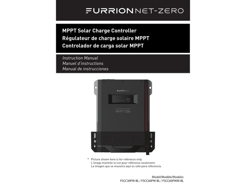
Furrion FSCC40PW2 User manual

Product picture is for reference only.
INSTRUCTION MANUAL
40A WALL MOUNT MPPT SOLAR CHARGE
CONTROLLER WITH BT APP
60A WALL MOUNT MPPT SOLAR CHARGE
CONTROLLER WITH BT APP
MODEL: FSCC40PW2 / FSCC60PW2
LIPPERT NO.: 2023006262 / 2023006263

CCD-0007727 Rev: 06-01-23 - 1 -
Welcome
English
Thank you and congratulations for purchasing the Furrion®MPPT solar charge controller. Before
operating your new product, please read these instructions carefully. This instruction manual contains
information for safe use, installation and maintenance of the product.
Please keep this instruction manual in a safe place for future reference. This will ensure safe use and
reduce the risk of injury.
The manufacturer does not accept responsibility for any damages due to not observing these
instructions.
Supplier’s Declaration of Conformity
47 CFR § 2.1077 Compliance Information
Unique Identier
Trade Name: Furrion
Model No.: FSCC40PW2, FSCC60PW2
Responsible Party – U.S. Contact Information
Furrion Innovation Center & Institute of Technology
22244 Innovation Drive, Elkhart, IN 46514-5514, USA
FCC Compliance Statement
Any Changes or modications not expressly approved by the party responsible for compliance could void the user's authority to
operate the equipment.
Note: This equipment has been tested and found to comply with the limits for a Class B digital device, pursuant to part 15 of the
FCC Rules. These limits are designed to provide reasonable protection against harmful interference in a residential installation.
This equipment generates uses and can radiate radio frequency energy and, if not installed and used in accordance with the
instructions, may cause harmful interference to radio communications. However, there is no guarantee that interference will not
occur in a particular installation. If this equipment does cause harmful interference to radio or television reception, which can be
determined by turning the equipment o and on, the user is encouraged to try to correct the interference by one or more of the
following measures:
– Reorient or relocate the receiving antenna.
– Increase the separation between the equipment and receiver.
– Connect the equipment into an outlet on a circuit dierent from that to which the
receiver is connected.
– Consult the dealer or an experienced radio/TV technician for help.
This equipment complies with FCC radiation exposure limits set forth for an uncontrolled environment. This equipment should
be installed and operated with minimum distance 20cm between the radiator & your body.
This device complies with Part 15 of the FCC Rules. Operation is subject to the following two conditions: (1) This device may not
cause harmful interference, and (2) this device must accept any interference received, including interference that may cause
undesired operation.
Declaration for Canada
This device contains licence-exempt transmitter(s)/receiver(s) that comply with Innovation, Science and Economic Development
Canada’s licence-exempt RSS(s). Operation is subject to the following two conditions:
(1) This device may not cause interference.
(2) This device must accept any interference, including interference that may cause undesired operation of the device.
The device meets the exemption from the routine evaluation limits in section 2.5 of RSS 102 and compliance with RSS-102 RF
exposure, users can obtain Canadian information on RF exposure and compliance.
This transmitter must not be co-located or operating in conjunction with any other antenna or transmitter. This equipment
should be installed and operated with a minimum distance of 20 centimeters between the radiator and your body.

CCD-0007727 Rev: 06-01-23
- 2 -
Contents
English
Welcome...................................................................................................................................1
Contents ...................................................................................................................................2
Important Safety Instructions...........................................................................................3
General Safety Precautions......................................................................................................................3
Charge Controller Safety...........................................................................................................................3
Battery Safety................................................................................................................................................3
About Your Product..............................................................................................................4
General Information ...................................................................................................................................4
Key Features ..................................................................................................................................................4
Product Overview .................................................................................................................5
Dimensions....................................................................................................................................................5
Structure .........................................................................................................................................................6
Accessory - Temperature Sensor............................................................................................................6
Bluetooth Communication ......................................................................................................................6
MPPT Charging Technology and Stages.......................................................................7
Four Stage Charging Process...................................................................................................................7
Installation ...............................................................................................................................9
Read before installation............................................................................................................................9
Mounting Location Requirements .....................................................................................................10
PV Array Recommendations................................................................................................................. 11
Wire Size and Fuse Recommendations.............................................................................................12
Solar Charge Controller Connections and Steps...........................................................................13
Grounding...................................................................................................................................................14
Operation...............................................................................................................................15
LED Indications.......................................................................................................................................... 15
Button Functions ......................................................................................................................................15
LCD Screen Indications...........................................................................................................................16
Advanced Modes & Parameter Settings...........................................................................................18
Protections, Troubleshooting, and Maintenance.....................................................21
Protection Features..................................................................................................................................21
Fault Indication & Troubleshooting....................................................................................................22
Care and Maintenance...........................................................................................................................22
Specications........................................................................................................................23

CCD-0007727 Rev: 06-01-23 - 3 -
Important Safety Instructions
English
IMPORTANT: SAVE THESE INSTRUCTIONS– This
manual contains important instructions for
Models FSCC40PW2 and FSCC60PW2 that shall
be followed during installation and operation
of the charge controller. The following symbols
are used throughout the manual to indicate
potentially dangerous conditions or important
safety information.
WARNING
Indicates a potentially dangerous condition. Use
extreme caution when performing this task.
CAUTION
Indicates a critical procedure for safe and
proper operation of the controller.
NOTE: Indicates a procedure or function that is
important to the safe and proper operation of
the controller.
General Safety Precautions
Read all instructions and warnings in the
manual before installation.
●There are no user serviceable components
inside of the controller. DO NOT disassemble
or attempt to repair the controller.
●Mount the controller indoors. Prevent
exposure to the elements and do not allow
water to enter the controller.
●Install the controller in a well ventilated area
as the unit may become hot during normal
operation.
●Install appropriate external fuses or circuit
breakers.
●Disconnect all connections with the solar
panels and the fuses or circuit breakers prior
to controller installation or adjustment.
●Ensure connections remain tight to avoid
excessive heat.
Charge Controller Safety
●NEVER connect the solar panel array to the
controller without connecting a battery to
the controller rst.
●Ensure input PV voltage does not exceed 95
VDC (25°C) for FSCC40PW2, FSCC60PW2 to
prevent permanent damage. Use the Open
Circuit Voltage (Voc) parameter of the solar
panels to make sure the voltage does not
exceed this value when connecting panels
together.
Battery Safety
●For use with sealed lead acid, GEL, AGM
(absorbent glass mat), and LiFePO4
batteries.
●Explosive battery gases may be released
while charging certain batteries. Be certain
there is enough ventilation to release the
gases.
●Be careful when working with lead acid
batteries. Wear eye protection and have
fresh water available in case there is contact
with the battery acid.
●Carefully read battery manuals before
operation.
●Do NOT let the positive (+) and negative (-)
terminals of the battery touch each other.
●Properly dispose of battery when replaced.

CCD-0007727 Rev: 06-01-23
- 4 -
About Your Product
English
General Information
The Furrion Maximum Power Point Tracker
(MPPT) series controllers can increase
charging eciency by up to 30% compared to
conventional Pulse Width Modulation (PWM)
controllers. Furrion’s sophisticated four stage
charge control system can be congured to
optimize charge parameters to precise battery
charging requirements.
The device is fully protected against voltage
spikes, over temperature, reverse polarity
of battery and solar connections. Battery
temperature sensors are also available to further
protect and improve battery performance
using automatic temperature compensation
algorithm feature.
The device has an onboard LCD screen to
display various solar and battery parameters
for quick monitoring and a button interface to
customize settings with ease. It also features
Bluethooth wireless communication via a
mobile application for users to conveniently
monitor and customize parameters and track
performance and usage over time.
Key Features
●Compatible with 12V or 24V battery system.
●Innovative Maximum Power Point Tracking
(MPPT) technology to maximize tracking
eciency >99.9%.
●Full digital technology, high charge
conversion eciency up to 98%.
●Onboard LEDs and an LCD screen to display
operational data and device working
conditions easily.
●Real-time energy statistics function.
●Flexible System battery type selection:
Liquid, Gel, AGM, and Lithium
●Four stages battery charging process: MPPT,
boost, equalization, oat stages.
●Extends battery life through accurate
remote temperature sensor for auto
temperature compensation and corrective
charging.
●Dual automatic protection to avoid
exceeding the rated charging power and
current.
●Full protection against solar panel short
circuit & reverse polarity, battery over
voltage & reverse polarity and Electrostatic
Discharge (ESD).
●Multiple load control modes: Always on,
Dusk to Dawn, Evening and Manual mode.
●Built in Bluetooth communication capability.
●Dedicated and intuitive smart phone APP for
easy monitoring and customization.
●Monthly charging data can be calculated
and displayed by grouping and graphs.
●Advanced EMC & thermal design.

CCD-0007727 Rev: 06-01-23 - 5 -
Product Overview
English
Dimensions
60A MPPT Solar Charge Controller
40A MPPT Solar Charge Controller
Fig. 1Fig. 1
Fig. 2Fig. 2

CCD-0007727 Rev: 06-01-23
- 6 -
Product Overview
English
1. Heat sink
2. Mounting holes
3. LEDs & LCD screen
4. Buttons (SET, BROWSE)
5. Temperature sensor port
6. Non-functional
(For service use only)
7. Auxiliary Load + / - connections
8. Battery + / - connections
9. Solar panel + / - connections
10. M6 Grounding lug
Structure
Fig. 3Fig. 3
Accessory - Temperature Sensor
An external temperature sensor (not included) is used to collect battery temperature to perform auto
temperature compensation function. The temperature sensor is connected to the controller indicated
by the item 5 shown in the gure 3.
Bluetooth Communication
Download the dedicated Bluetooth app - 'Furrion Solar' for Android/iOS mobile phones from the app
store. Refer to the Help/Support section on the app for detailed instructions.

CCD-0007727 Rev: 06-01-23 - 7 -
MPPT Charging Technology and Stages
English
Fig. 4Fig. 4
Maximum Power Point Tracking (MPPT) is an advanced tracking algorithm that keeps track of input
power coming from the solar panels in real time to maximize the charger’s performance and improve
the system’s total eciency.
The amount of solar energy available during a day varies based on conditions like geographical
location, time of the day, inclination angle of the solar panels, relative humidity and impurities in the
air, surface cleanliness of the solar panels etc. With all these conditions at play, eecting the amount
of energy reaching the panels, it is important that every bit of converted electrical energy is used to
charge batteries as eciently as possible. The MPPT charging technology is designed to track this
variable amount of energy coming from the panels and adjust the voltage and current parameters to
maximize the battery charging eciency. The MPPT charging algorithm comprises of four stages that
provide rapid, ecient, and safe battery charging.
Four Stage Charging Process
The charge controller’s 4-stage charging process is illustrated in the gure below.
MPPT Charge Stage
In this stage, the battery voltage has not yet reached boost voltage and 100% of available solar power
is used to recharge the battery.
Boost Charge Stage
In this stage, when the battery voltage reaches the Boost voltage setpoint value, the charger uses a
constant voltage to charge the battery to prevent excess heating.

CCD-0007727 Rev: 06-01-23
- 8 -
MPPT Charging Technology and Stages
English
WARNING: Risk of explosion!
Equalizing ooded battery can produce explosive gases, so well ventilation of battery box
is necessary.
Float Charge Stage
The controller reduces the voltage to the oating stage, charging with a smaller voltage and current.
It will reduce the temperature of battery and prevent the gassing, also charging the battery slightly
at the same time. The purpose of Float stage is to oset the power consumption caused by self-
consumption and small loads in the whole system, while maintaining full battery storage capacity.
In Float stage, loads can continue to draw power from the battery. If the system load(s) exceed the
solar charge current, the controller will no longer be able to maintain the battery at the Float setpoint.
Should the battery voltage remains below the boost reconnect charging voltage, the controller will
exit Float stage and return to Bulk charging.
Equalize Charge Stage.
Certain types of batteries benet from periodic equalizing charge, which can stir the electrolyte, balance
battery voltage and complete chemical reaction. Equalizing charge increases the battery voltage, higher
than the nominal battery voltage, which gasies the battery electrolyte. If it detects that the battery is
being over discharged, the solar controller will automatically turn the battery to equalization charging
stage, and the equalization charging will be 120mins. Equalizing charge and boost charge are not carried
out constantly in a full charge process to avoid too much gas precipitation or overheating of battery.

CCD-0007727 Rev: 06-01-23 - 9 -
Installation
English
Read before installation
●This charge controller must only be used in Photo-Voltaic (PV) systems in accordance with
requirements given in this user manual and the specications of other system components
provided by their manufacturers. No energy source other than a solar panel or array may be
connected to the PV charge controller referred herein.
●PV-modules must always be disconnected prior to the installation and adjustments of the charge
controller; Make sure the circuit breaker, fuse or disconnect switches of battery terminals are
breaking the circuit path.
●Verify the battery voltage parameter meets the voltage range of the charge controller.
●Batteries store a large amount of energy, never short circuit a battery under any circumstances.
We strongly recommend connecting a protection fuse directly to the battery terminal for
protection in case of short circuiting the battery.
●Certain types of batteries can produce ammable gases. Avoid provoking any sparks, using re or
any exposed ame close to any batteries. Make sure that the battery enclosure is well ventilated
to disperse any gases.
●Only use insulated tools and avoid placing (any) metal objects near/close to batteries.
●Be extremely cautious when working with batteries. Wear eye protection. Have fresh water
available to immediately wash and clean any contact with battery acid. Get immediately medical
aid in case of any hazard that may occur.
●Be aware that voltages on given system components, terminals or wires can be a multiple of
battery voltage and keep your hands always dry and protected by proper (approved) electrician
gloves when working on PV-Systems.
●Prevent any water from entering the controller, outdoor installation must avoid any direct
sunlight and penetration of any water (e.g., rain) and humidity.
●After installation make sure that all connections are properly secured without any loose
connections to eliminate the possibility of any hot electrical connection spots.
●Do not touch the wire terminal screws with bare hands or with uninsulated metal objects or tools.
CAUTION: Please read all instructions and precautions in the manual before
proceeding with the installation!

CCD-0007727 Rev: 06-01-23
- 10 -
Installation
English
Fig. 5Fig. 5
Mounting Location Requirements
●Do not subject the solar charge controller to direct sunlight or any other heat sources. Protect the
charge controller from any dust, dirt, and moisture.
●Mount it at to a vertical wall. If there is a backing material installed on the wall, make sure that it
is non-ammable material.
●Maintain a minimum clearance of 6 inches (or 15 cm) above and below and around the controller
to ensure unhindered air circulation. Mount the charge controller as close to the batteries as
possible (for accurate voltage sensing).
●Mark the position of the charge controller’s mounting holes on the wall, drill 4 holes and insert
dowels and ax the charge controller to the wall using appropriate screws and the cable terminal
openings facing downwards.
Fig. 6Fig. 6

CCD-0007727 Rev: 06-01-23 - 11 -
Installation
English
PV Array Recommendations
●The solar panels can be interconnected in either series or parallel conguration in a Photo-Voltaic
(PV) array. It is recommended to use only one type of panels (with identical parameters) in an
array.
For example:
o Connecting two or more 165W (FSFP16MW2-BL) panels in series or parallel
o Connecting two or more 180W (FSFP18MW-BL) panels in series or parallel
o Connecting two or more 370W (FSFP37MW2-BL) panels in series or parallel
●Mismatching solar panels in series or parallel is not recommended as it will lower the overall
output and eciency of the PV array.
For example:
o Connecting one 165W panel with a 180W or a 370W panel in a series or parallel
●In Series conguration, the negative terminal of the rst solar panel is connected to the positive
terminal of the second panel and so on in a daisy chain fashion (see gure below). This will result
in addition of the output voltage and wattage of the panels in the array and the output current of
the total array will remain the same as output current of one solar panel.
For example:
o Consider a PV array of two Furrion 165W solar panels (PN: FSFP16MW2-BL) connected in
series conguration.
Fig. 7Fig. 7

CCD-0007727 Rev: 06-01-23
- 12 -
Installation
English
For a single Furrion 165W solar panel (PN: FSFP16MW2-BL) the voltage at max. power is 17.9V, current
at max. power is 9.7A and the max. power is 165W.
After connecting two panels in series conguration,
The resultant array’s voltage at max. power will be 35.8V, current at max. power is 9.7A and total max.
power of the array is 330W.
The Furrion MPPT technology based solar charge controller can function eciently and convert
almost 98% of its input solar power into charging power with the help of the added voltage resulting
from a series connection of solar panels. The wire gauge of the array can remain the same, as series
conguration will keep the output current same as a single panel. Hence, it is recommended to
connect solar panels in series conguration in an array when using the MPPT solar charge controller.
When connecting solar panels in an array, care must be taken so that the resultant array voltage and
power parameters do not exceed the charger specications shown below.
Model
Parameter 40A charger (FSCC40PW2) 60A charger (FSCC60PW2)
Maximum input PV power 520W 750W
Maximum PV Open Circut
Voltage (VOC)95V 95V
Wire Size and Fuse Recommendations
●Wiring and installation methods must comply with national and local electrical code/
specications.
●The wiring specications of the PV and battery system must be selected according to the rated
currents specied.
●Since the PV outputs can vary due to the array connection method, the minimum wire size must
be in accordance with the maximum array short-circuit current.
●Please use PV Photovoltaic wire for connection of the array to the charge controller.
●It is recommended to install a fuse between the charger and the battery on the positive wire.
Location of the fuse should be closer to the battery. The fuse rate must be 1.2 - 1.5 times more
than the maximum rated charge current of the solar charge controller.
Please check the following table for wiring specications:
Model Rated charge
current
PV Wire Gauge
(AWG)
Battery Wire
Gauge (AWG)
Rated Discharge
current
(Load terminals)
Load terminal
wire Gauge
(AWG)
40A charger
(FSCC40PW2) 40A 10 8 30A 10
60A charger
(FSCC40PW2) 60A 8 6 30A 10

CCD-0007727 Rev: 06-01-23 - 13 -
Installation
English
Solar Charge Controller Connections and Steps
Fig. 8Fig. 8
Fig. 9Fig. 9
40A charger model connection schematic
60A charger model connection schematic

CCD-0007727 Rev: 06-01-23
- 14 -
Installation
English
Grounding
Fig. 10Fig. 10
CAUTION: For common-negative system, such as
motorhome, it is recommended to use a common
negative-type controller.
1. Connect the accessories such as the temperature sensor. The 2-pin connector of the temperature
sensor cable connects to the temperature sensor port on the charger. Connect the other end with
an eyelet terminal to the battery negative terminal to measure the battery temperature.
2. Remove terminal cover before installing wires.
3. Connect the load cables (if applicable) to the charger matching the polarity as indicated by the
symbols on the charger. To avoid tension in the cables, connect the cables to the load rst and
then connect them to the charge controller.
4. Connect the battery cables to the charger matching the polarity as indicated by the symbols on
the charger. Make sure a properly rated fuse is installed in line on the cable for the positive lead of
the battery.
5. Connect the PV array cables to the charger matching the polarity as indicated by the symbols on
the charger.
Note: Solar panels produce voltage and current whenever they are exposed to light. When
connected in a circuit, the amount of current produced by the solar panels is directly proportional
to the light intensity. Be careful when connecting the PV array cables to the charger terminals.
The connection of a properly rated fuse is optional but they add additional system safety. A
disconnect switch can be very convenient if need arises to disconnect the solar array to the
charger for maintenance and troubleshooting.
6. Add back terminal cover. Ensure wires or terminals are not exposed after installation.
7. Connect an 8AWG cable with a crimped eyelet terminal to the ground lug on the charge
controller and connect the other end to the chassis grounding point.
8. Make sure all the cables are securely attached to the charger terminals. If a disconnect switch is
present in line between the solar array and the charger, turn it on to supply power to the charge
controller.
Note: Install the provided rubber plugs on top of the wire terminal screws to avoid accidental
contact with the high voltage connections. Use insulated tools to remove them if needed.
9. Observe the operational indications like the LEDs, icons on LCD screen or the parameters on the
Bluetooth app for further information.
The 40A and the 60A charge controllers are equipped with
an M6 size ground lug on the side of the heat sink. It is
recommended to use an 8AWG conductor with an eyelet
terminal for grounding the controller to the vehicle chassis in
case grounding is required.

CCD-0007727 Rev: 06-01-23 - 15 -
Operation
English
LED Indications
LED Status Function
Green
(PV Panel) On Solar panel is connected, not charging.
Fast ash (0.1/0.1s) MPPT charging
Flash (0.5/0.5s) Equal or Boost Charging
Slow ash (0.5/2s) Float Charging
Yellow
(Battery) On Battery is normal
O Over voltage protection active
Fast ash (0.1/0.1s) Low voltage protection active
Slow ash (0.5/2s) Battery voltage is low
Red
(Load) On Load is on.
O Load is o.
Fast ash (0.1/0.1s)
Short circuit or over current protection active
Slow ash (0.5/2s) Over temperature protection active
Blue
(Communication)
O No communication
Fast ash (0.1/0.1s) Normal communication
Button Functions
Function Operation
Browse Interface Short press Browse.
Static display Press the SET and BROWSE keys at the same time for 1s, the LCD screen
will lock the interface.
Press the SET and BROWSE keys again for 1s, the LCD interface will unlock
and start scrolling.
Setting parameter Press the SET key for 1s to enter the setting mode when the icon appears
on the display interface, and exit automatically after 30s or press the SET.
Load On/O When the controller is working in street lamp mode, press the SET key for 3s
to turn on the load, press the SET key again or 1min later the load will be
turned o.

CCD-0007727 Rev: 06-01-23
- 16 -
Operation
English
LCD Screen Indications
*PV array charge ampere hours and load ampere hours are o after power failure.
Item Icon Status
PV Array
Charging
PV voltage
PV current
PV ampere hours of the day*
The total charge ampere hours of the
solar panel
Battery
Battery capacity
Battery voltage (Programmable LVD)
Battery current
Battery type (Programmable)
Temperature (Can clear Bluetooth Device
Password)
Load
Load voltage (Programmable LVR)
Load current
Load ampere hours of the day*
The total discharge ampere hours of the
load
Load mode (Programmable)
Status Description

CCD-0007727 Rev: 06-01-23 - 17 -
Operation
English
Parameters Default Display Order
Browsing The Interface
Press BROWSE to scroll through the parameter interface.

CCD-0007727 Rev: 06-01-23
- 18 -
Operation
English
Display Icon Battery Type
GEL
AGM
Lithium
Liquid (Default)
Advanced Modes & Parameter Settings
When the icon appears in the display interface, it means that the parameters can be set. Press
the SET key for 1s, then icon ashes, press BROWSE to change the parameter; when the setting
is nished, you can wait 30 seconds to exit the setting mode automatically, or you can press the SET
key to exit the setting mode.
Battery Type Selection
When the LCD displays as above, press the SET key for 1s, the icon ashes, now you can select the
battery type.
Charging Voltage Parameters (Liquid, GEL, AGM)
When choosing Liquid, GEL or AGM type battery, the parameters of boost, and oat charge voltage
can be set by Bluetooth App. The range of parameters is as follows. The following voltage parameters
are for a 25°C/12V system. For a 24Vsystem, the displayed values need to be doubled.
Charging Stage Boost Equalization Float
Charging Voltage Range 14.0~14.8V 14.0~15.0V 13.0~14.5V
Default Charging Voltage 14.5V 14.8V 13.7V
Charging Voltage Parameters (Lithium)
When choosing a lithium battery type, the overcharge protection and overcharge recovery
voltage of lithium battery can be set by the Bluetooth APP.
Charge target voltage range: 12/24V: 10.0-32.0V (default:14.4V)
Charge recovery voltage setting range: 12/24V: 9.2-31.8V (default:14.0V)

CCD-0007727 Rev: 06-01-23 - 19 -
Operation
English
Display Icon Load Mode Description
Always ON Mode:
The load output is always switched ON.
Dusk to Dawn Mode: The load output is switched ON
between sunset and sunrise.
Evening Mode: The load output will be switched ON for
2 ~ 9hours after sunset.
Manual Mode: The load output can be switched ON and
OFF manually by pressing the SET shortly.
Auxiliary Load Mode
The charge controller is equipped with an auxiliary load terminal in case a user needs to connect a
light load device (For e.g., a 12V LED lamp) directly to the solar charge controller instead of the battery.
The terminals are protected by a rubber plugs to avoid improper usage and provide user safety. A
blunt tipped tweezers or a needle nose pliers can be used to eject the rubber plugs to access the
screw terminals on the charge controllers.
When the LCD shows the above icon, press the SET key for 1s, the icon ashes, now you can set the
load mode.
1. Always on Mode: When the controller is set to always ON mode, no matter the charging or
discharging state, the load is always powered ON (except in when in protection state.
2. ‘Street-Lamp’ Function: When the load is set to Dusk to Dawn or Evening mode, the voltage and
the Day/Night delay time can be set via the Bluetooth APP, and the load can be turned on or o
by the test function during the day charging process.
2.1 Day/Night threshold voltage: The controller recognizes day and night based on the
solar array open circuit voltage. The day/night threshold voltage parameter can be modied
according to local light conditions and the solar array used.
Day/Night threshold setting range: 3.0~10.0V/6.0~20.0V (Default: 8/16V for 12/24V systems)
2.2 Day/Night delay time: In the evening, when the solar array open circuit voltage reaches
the setting day/night detect voltage, user can adjust the day/night delay time to make the
load turn on a little bit later.
Day/Night delay time setting range: 0~30min (Default: 0min)
2.3 Test Function: When the controller is working in Dusk to Dawn or Evening mode, press the
SET key for 3s to turn on the load. Press the SET key again or the load turns o automatically after
1 minute. If the controller is operating in always on mode, the test function does not work.
3. User-dened Mode: If the load mode is selected "USE", then you can switch on and o the load
output manually by pressing SET shortly.
The default switching state of the load in manual mode can be changed by Bluetooth APP. At the
same time, the output to the load can be turned on or o.
●If the controller turns o the load due to low voltage protection, overcurrent
Protection, short-circuit protection or over temperature protection, the load will
turn on automatically when the controller recovers from protection state.
●Please note: Pushing the SET button can still activate the function of the key,
even during of the above four kinds of protection states.
This manual suits for next models
3
Table of contents
Languages:
Other Furrion Controllers manuals
Popular Controllers manuals by other brands

emaux
emaux FLEX Series Installation and operation manual

NOVAK
NOVAK MONGOOSE CRAWLER - BASIC SETUP GUIDE 1-2009 Setup guide

Manzanita Micro
Manzanita Micro Z1K-LV owner's manual

SMC Networks
SMC Networks AR20 Series Operation manual

Emerson
Emerson Dixell XR44CX Installing and operating instructions

CKD
CKD KBX-10 instruction manual