Furrion FWH09A-AM User manual

2.4GPM Tankless Gas Water Heater
User Manual Model: FWH09A-AM
* Picture shown here is for reference only.
https://furrion.com/pages/
downloads-climate
* To view the multi-language user manual, please access the link or scan the QR code.
* Pour obtenir le manuel d’utilisateur multilingue, accédez au lien ou scannez le QR code.
* Para ver el manual de usuario en otros idiomas, acceda al siguiente enlace o escanee el código QR.

1
Thank you for purchasing this Furrion® product. Before operating your new product, please read these instructions carefully.
This will ensure safe use and reduce the risk of injury. This instruction manual contains information for installation, operation,
maintenance of the product and safe use.
Please keep this instruction manual in a safe place for future reference. Be sure to pass on this manual to any new owners of
this product.
The manufacturer does not accept responsibility for any damages due to not observing these instructions.
WARNING: If the information in these instructions is not followed exactly, a fire or explosion
may result causing property damage, personal injury or death.
−Do not store or use gasoline or other flammable vapors and liquids in the vicinity of this or any
other appliance.
−WHAT TO DO IF YOU SMELL GAS
●Evacuate all persons from vehicle.
●Shut off gas supply at gas container or source.
●DO NOT touch any electrical switch, or use any phone or radio in vehicle.
●DO NOT start vehicle’s engine or electric generator.
●Contact nearest gas supplier or qualified service technician for repairs.
●If you cannot reach a gas supplier or qualified service technician, contact the nearest fire
department.
●DO NOT turn on gas supply until gas leak(s) has been repaired.
−Installation and service must be performed by a qualified installer, service agency or the gas
supplier.
Table of Contents
Table of Contents................................................................................................................................................................................... 1
Explanation of Symbols ........................................................................................................................................................................ 2
Important Safety Instructions.............................................................................................................................................................. 2
Ensuring a Safe Operating Environment ...................................................................................................................................................................................2
Responsibilities of the Operator....................................................................................................................................................................................................2
About Your Product ............................................................................................................................................................................... 3
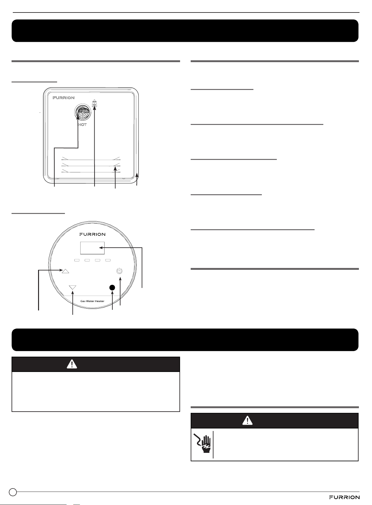
Product Overview ................................................................................................................................................................................................................................3
Product Features..................................................................................................................................................................................................................................3
Basic Function .......................................................................................................................................................................................................................................3
Installation .............................................................................................................................................................................................. 3
General Installation Safety...............................................................................................................................................................................................................3
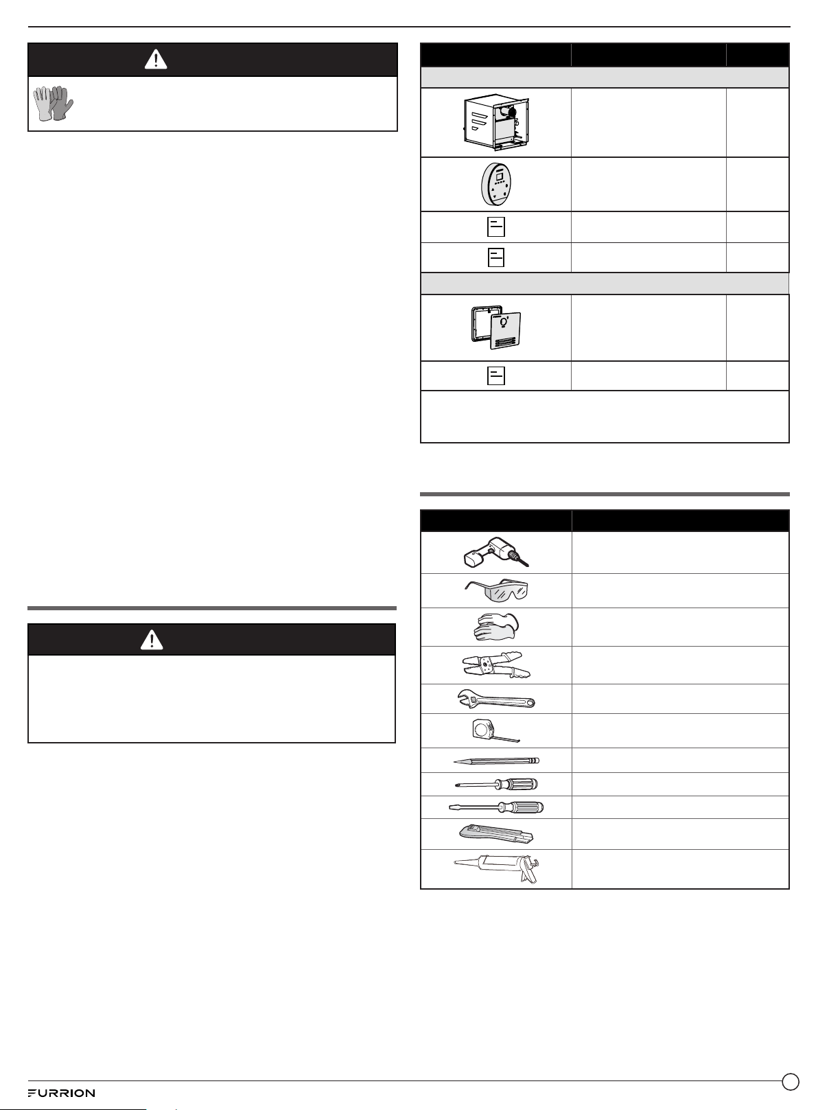
What’s in the Box ..................................................................................................................................................................................................................................4
Tools Required (Not Provided).......................................................................................................................................................................................................4
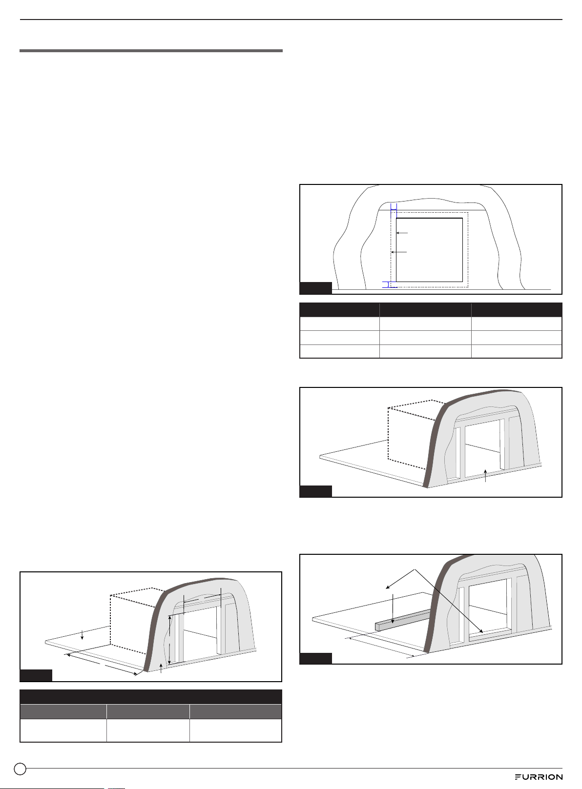
Prepare Cutout Opening...................................................................................................................................................................................................................5
Prepare Utilities.....................................................................................................................................................................................................................................6
Prepare Wall Control...........................................................................................................................................................................................................................7
Prepare Water Heater.........................................................................................................................................................................................................................8
Prepare Water Heater Door.............................................................................................................................................................................................................8
Water Heater Installation .................................................................................................................................................................................................................8
Leak Check ............................................................................................................................................................................................................................................10
Functional Test ......................................................................................................................................................................................................................................11
Operation................................................................................................................................................................................................. 11
Controller Operation...........................................................................................................................................................................................................................11
Safe Operation ......................................................................................................................................................................................................................................11
Water Control Valve.............................................................................................................................................................................................................................12
High Altitude Use .................................................................................................................................................................................................................................12
Cleaning and Maintenance ................................................................................................................................................................... 12
Storage and Transit.............................................................................................................................................................................................................................12
Winterizing Water Heater..................................................................................................................................................................................................................12
Routine Inspection...............................................................................................................................................................................................................................13
Filter Cleaning........................................................................................................................................................................................................................................14
Pressure Safety Valve Maintenance............................................................................................................................................................................................14
Hard Water and Decalcification.....................................................................................................................................................................................................14
Error Code............................................................................................................................................................................................... 15
Troubleshooting ..................................................................................................................................................................................... 16
Wiring Diagram ....................................................................................................................................................................................... 17
Specifications......................................................................................................................................................................................... 17

2
Explanation of Symbols
This manual has safety information and instructions to help
you eliminate or reduce the risk of accidents and injuries.
Always respect all safety warnings identified with these
symbols. A signal word will identify safety messages and
property damage messages, and will indicate the degree or
level of hazard seriousness.
DANGER
Indicates an imminently hazardous situation which, if not
avoided, will result in death or serious injury.
WARNING
Indicates a potentially hazardous situation which, if not
avoided, could result in death or serious injury.
CAUTION
Indicates a potentially hazardous situation which, if not
avoided, may result in minor or moderate personal injury, or
property damage.
Important Safety Instructions
Read these instructions carefully to ensure safe and correct
operation of your appliance. Retain the instruction manual
and installation instructions for future use or for subsequent
owners.
Ensuring a Safe Operating
Environment
DANGER
Suffocation or Fire Hazard
●Exhaust gases are hot and contain carbon monoxide,
do not breath or obstruct the exhaust gases.
Failure to follow the instruction will lead to serious injury,
property damage or death.
●NEVER use this appliance in enclosed spaces or tents.
●ALWAYS turn the appliance off, and shut off fuel supply
while parking the RV in an enclosed space, such as a
garage or repair shop.
●NEVER place seating or picnic tables in direct path of the
exhaust outlet.
●DO NOT use this water heater without a working
carbon monoxide detector installed in the RV. Follow
the manufacturer's instruction and guidelines for its
installation.
●ALWAY keep the air inlet and exhaust outlet free of
obstructions in order to ensure clean combustion.
●DO NOT place articles on or against the appliance.
●DO NOT lean any objects against the water heater’s
access door or place any foreign objects within 24" (610
mm) of the access door.
●DO NOT use or store flammable materials near the
appliance.
●DO NOT spray aerosols in the vicinity of the appliance
while it is in operation.
●DO NOT modify the appliance.
Responsibilities of the Operator
●The operator is responsible for their own health and
safety, persons with pacemakers should discuss with their
doctor before opening the access door, or performing any
service repairs.
●The operator is responsible for the water quality used in
the appliance.
●The operator is responsible for all routine inspections
found in the Cleaning and Maintenance section of this
manual.
●The operator is responsible for using and maintaining gas
cylinders as specified by the RV manufacturer.
●The operator is responsible for ensuring no spray water
enters the appliance when cleaning the RV.
●The operator is responsible for using the appliance for
potable water only. They are responsible for ensuring
non-potable water sources, components, or heating
systems, new or old, are not connected in any means to
the appliance.
While Driving
●The operator is responsible for ensuring all components
are seated and locked in place before moving the RV,
check the following:
− Access door is flush with the mounting plate.
− Door locker is engaged. (Fig. 1)
Door Locker
Fig. 1
●The operator is responsible for ensuring the gas system
is turned off at the gas cylinders before transit. Turn off all
necessary valves as indicated by the RV manufacturer.
●The operator is responsible for making sure the appliance
is off when refueling, traveling through tunnels, parking in
garages or car ports, or on ferries.

3
About Your Product
Product Overview
Access Door
Exhaust Vent Door Trim
Door Cover
Door Latch
Wall Controller
POWER
UP
DOWN
o
F /
o
C
ON/OFF
O
F
O
CFLAME
Up Button Down Button Temperature
Unit Switch Button
Power Button
LED Display
Product Features
The appliance is equipped with the following features:
Flame Monitoring
If the flame goes out, the gas supply to the burner is switched
off.
Low-Voltage/Over-Voltage Shutdown
If the voltage drops below 10V DC (or rises above 17V DC),
the appliance shuts off.
Over-current Protection
If there is a short circuit in the appliance (>10 A), a fuse on the
control unit is activated and the appliance is switched off.
Flue Fan Monitoring
If there is a failure of the flue fan, the gas supply to the burner
is switched off.
Hot Water Temperature Monitoring
A water over-temperature switch avoids excessively high
water temperatures in case of an error.
Basic Function
Based on the hot water demand, the tankless water heater
will heat incoming cold water to a desired output temperature
by monitoring key sensors to regulate the thermal energy
released over a large heat exchanger. This creates a more
useful and energy efficient heating system versus the
conventional tank water heater that wastes fuel during re-
heat cycles and is limited on volume output.
Installation
DANGER
Suffocation and/or Fire Hazard
●Observe all installation material in accordance with
governing codes and ordinances.
Failure to the follow instructions will result in serious injury,
property damage, or death.
The installation of this appliance, along with all subsequent
components to support installation and operation of the
appliance, must conform with country, state and local codes.
In the absence of such codes, refer to the latest editions of:
●USA:
− NFPA 1192 - Recreational Vehicles (RV)
− ANSI A119.5 - Park Model RV
− ANSI/RVIA LV - Low Voltage Standard
− NFPA 70 - National Electric Code
●Canada:
− CSA Z240 RV Series - Recreational Vehicles
− CSA Z241 Park Model RV
− CSA C22.1 - Canadian Electric Code
General Installation Safety
WARNING
Electrical Shock and/or Fire Hazard
●Disconnect power before installation.
●Turn off all gas to the supply system.
Failure to do so can result in serious injury or Death.

4
CAUTION
Always wear protective gear such as gloves,
eyewear and clothing to avoid injuries during
installation and servicing of the product.
●For Recreational Vehicle (RV) installation only!
NOTE: This water heater is certified ANSI Z 21.10.3 /
CSA4.3-2019 for installation in Recreational Vehicles (RV)
and is not for use in Marine or Space Heating Applications.
RV’s are recreation vehicles, having their own power or
towed by another vehicle, designed as temporary living
quarters for recreation, camping, or travel use.
●Any Installation must be performed by a qualified person,
in accordance with this instruction manual.
●DO NOT use test pressures higher than 40in-wc (1.45PSI)
to test the gas leaks.
●DO NOT attempt to modify the appliance.
●DO NOT alter the appliance for a positive grounding
battery system.
●DO NOT move the appliance by grabbing the interior
components.
●Make sure all exhaust gases are directed outside the RV.
●Protect all combustible material from the exhaust gases.
●DO NOT draw air for combustion from occupied spaces.
●Always disconnect the 12V appliance (to protect the
control from surges that may occur) when performing
Dielectric (hi-pot) testing, welding, electrical, etc... work on
the coach.
●Only use with a proven 12V power source such as battery
or approved converter.
●DO NOT vent the water heater using a venting system
serving another appliance.
●DO NOT install directly into a shower, or near direct heat.
What’s in the Box
WARNING
Suffocation Hazard
●Dispose packaging material or keep from reach of small
children.
Failure to follow instruction could lead to serious injury or
death.
Remove product from packaging and make sure you have
the following list of items included. If any item is damaged or
missing, contact your Furrion dealer.
Part Description Quantity
Water Heater (For Model: FWH09A)
Main Body 1
Wall Controller 1
Instruction Manual 1
Warranty Manual 1
Door Assembly (Packed Separately)
Door assembly
(Assembly of door
cover and mounting
frame)
1
Installation Guide 1
NOTE: The door assembly for the water heater is packed in
another box, please contact your dealer if any of parts are
damaged or missing.
Tools Required (Not Provided)
Part Description
Electric Drill
Bit size: ⁄" (3mm) and ¾" (19mm)
Eye Protection
Gloves
Wire Stripper Pliers
Adjustable Wrench x 2
Tape Measure
Pencil
Phillips Screwdriver
Flat Blade
Cutting Knife
Sealant Gun

5
Prepare Cutout Opening
1. Choose a location to place the appliance, based on the
following criteria:
− DO NOT install in the front facing portion of the RV
to minimize damaging contamination from road grim,
debris and wet roads when traveling.
Important: It is not advised, but if installed on the rear
of the RV, the owner of this appliance must increase
routine inspections, from this manual, after each time
travelled.
− Do not install the appliance in an outdoor enclosed
area.
− DO NOT install the appliance in any location where the
exhaust vent may be covered or obstructed when a
swing door, bag door, slide out, pop up, etc. is partially
or fully extended.
− DO NOT install this appliance on any door or slide out
area.
− Do not install the appliance where the access door is
less than
- 9" (229mm) from any opening into the vehicle
- 36" (914) from any motor driven air intake
- 36" (914mm) from the any gas tank connection or
ventilation.
NOTE: These are guidelines, refer to NFP1192, Z240
RV edition for specific requirements.
− Choose a convenient location where supply water, LP
gas, and 12V DC is accessible to the back side of the
appliance for installation and servicing.
− The water heater is designed to be installed on a flat
floor (made of Wood or Linoleum) or a fixed platform.
− It is recommended that the appliance be located in a
central location to the hot water loads.
− Choose a location where clearances to combustible
surfaces and the appliance are:
- 1" to top surface.
- 0" to all other surfaces.
NOTE: To install on a carpeted area, a metal or wood panel that
extends at least 3 inches beyond the width and depth of the water
heater is required to install under the unit.
2. Create a cutout with the following dimensions A and B of
Fig. 2.
NOTE: The opening for the water heater should be right
angle corners.
C
A
B
Fig. 2
RV Flooring
RV Out-wall
Dimension
A B C
12⅝”~ 12¾”
(321~325mm)
12¾”~ 12⁄”
(324~326mm)
Min. 23½”
(Min. 597mm)
3. Make sure that the front edge of the opening is
surrounded by a solid frame to firmly anchor the water
heater. If needed, construct the opening by using
1.5" x 1.5" min. wood or aluminum framing.
NOTE:
− Fiberglass, filon, and corrugated aluminum (Mesa 1")
are all acceptable exterior wall siding solutions.
− The exterior wall opening must be the same dimensions
with no radius corners.
4. Refer to depth "C" for minimum rear clearances, for such
items as cabinets, appliances and utility entry locations.
5. Refer to Fig. 3 for adequate spacing from other items on
the RV wall to the door assembly.
B
A
Fig. 3
Cutout
Spacing
Door Assembly A B
FWH09EA-PS/BL Min. 1¾” (45mm) Min. 1 ⅞” (47mm)
FWH41EA-PS/BL Min. 2¾” (70mm) Min. 1 ⅞” (47mm)
FWH46EA-PS/BL Min. 2¾” (70mm) Min. 2⁄” (72mm)
6. Make sure the appliance is supported by a solid floor or
platform with adequate weight-bearing capacity. (Fig. 4)
RV Flooring
Fig. 4
7. If necessary, create a platform to support the water heater.
Fig. 5 and Fig. 6 are some common solutions. Ensure
the platform is level front to back, and side to side after
securing to the RV.
6"~8”
(152~203mm)
B
Flooring
C
A
7”~11½"
(178~292mm)
Wooden Mat
Flush Platform
Fig. 5

6
6"~8”
(152~203mm)
B
Flooring
C
A
7”~11½"
(178~292mm)
Fig. 6
Flooring
Wooden Mat
Flush Platform
Existing Cutout
1. Determine your existing cut-out and choose the
appropriate door assembly. (Fig. 7)
A
B
Fig. 7
RV Flooring
RV Out-wall
Door Assembly and Description Existing Cutout Dimension
A B
FWH09EA-PS/BL
Door 16⅛” x 16⅛” (410x410mm)
12⅝” ~ 15”
321 ~ 381mm
12⁄” ~ 15”
322 ~ 381mm
FWH41EA-PS/BL
Door 16⅛” x 18⅛” (410x460mm)
12⅝” ~ 15”
321 ~ 381mm
12⁄” ~ 17”
322 ~ 432mm
FWH46EA-PS/BL
Door 18⅛” x 18⅛” (460x460mm)
12⅝” ~ 17”
321 ~ 432mm
12⁄”~ 17”
322 ~ 432mm
2. The opening may need to be adjusted to accomodate
installation requirements of Fig 2. Refer to the door
assembly packaging for additional installation
instructions, requirements and options for resizing the
opening. (Fig. 8)
FWH09EA-PS/BL FWH41EA-PS/BL FWH46EA-PS/BL
Fig. 8
Prepare Utilities
Refer to Fig 9, 10, 11 for a general connection diagram.
Gas Connection (Fig. 9)
Gas Inlet
Gas Supply
Gas Inlet
Fig. 9
Electrical wiring (Fig. 10)
Fig. 10
12V DC
Power
Supply
Wall
Controller
12V
15A
Blue
White -
12V DC
Ripple<1Vpp
Blue
Switch ON-OFF (Optional)
Wiring
Water plumbing (Fig. 11)
A
B
Fig. 11
Shower Tap 2 Tap 1
NOTE:
Valve A, B
Bypass Position
HOT Water Outlet
COLD Water Inlet
NOTE:
●The drawings are not intended to describe a complete
system. It is the installers responsibility to determine the
necessary components for a working system.
●The drawings do not imply compliance with state or
local code requirements or regulations. It is the installers
responsibility to make sure that the installation is in full
compliance with all state or local code requirements or
regulations.
●Optional: The bypass valve can be installed (Fig 11) to
facilitate winterizing the coach. It is not required as anti-
freeze can be used in the appliance, however additional
anti-freeze (about 1L) is required to fill the volume. Refer
to the winterizing section of this manual for instruction
methods.
Gas Plumbing
DANGER
Fire or Explosion Hazard
●Follow all applicable codes, regulations and instruction
material when performing service work
Failure to follow instruction will result in product damage,
serious injury or death.
●Fuel entering the appliance must be in gas phase, liquid
phase must not be used and will result in damage to the
product.
●This appliance is rated for 60,000 BTU/HR, 11~14in-wc.
(27.4~34.9mbar). Follow NFPA1192 and Z240 RV series
for proper pipe sizing based on additional gas burning
appliance loads.
●Use with LP gas (propane) only. Butane or any mixtures
containing more than 10% butane must not be used.
●The gas line must terminate with a ⅜" flared female
compression fitting to connect with the rear gas
connector of the appliance.

7
●A non Metallic Flexible gas hose must be rated for 149oF
(65oC). Anchor appropriately to prevent fatigue and failure
from wear edges.
●Make sure that the operating pressure of the gas supply
corresponds to the operating pressure of the appliance
11~14in-wc (27.4~34.9mbar).
1. Locate entry point for the plumbing to service the
rear of the appliance. Ensure entry point is not in the
footprint space of the appliance. (Fig. 2)
2. Feed gas line into proximity, leave enough length to
flex into position so that when connected no kinks are
created.
NOTE: An approved semi-flexible metallic pipe is
acceptable to connect as an extension from the gas
line to the appliance.
3. Terminate gas line with fittings to connect to the
appliance.
Electrical Wiring
WARNING
Electrical Shock Hazard
●Disconnect all power before performing any work.
●Always use a certified and proven 12V isolated power
supply, that is properly grounded to the RV.
●Follow all applicable codes, regulations and instruction
material when performing service work.
Failure to follow instruction could result in serious injury or
death.
●Wiring connected to or in proximity of the appliance must
be rated for 140°F (60°C) minimum.
●Use only insulated terminals for all electrical connections.
●The appliance requires a power source that can
adequately provide 10~17V DC to function properly.
Contact furrion for available Power centers, converters
and distribution panels.
1. Select a distribution branch greater than 3A, preferably
15 amp, to provide nominal 12V to the appliance from the
distribution panel.
NOTE: The appliance has a built in 10A fuse, serviceable
from the front of the product. The appliance can be on
a dedicated or shared branch circuit with the same or
higher rating.
Optional: A power switch can be placed in the living
quarters for convenience, but not required as a switch is
located externally on the appliance. If the switch is fused,
make sure it is rated for at least 3amps. See Fig. 10 for
reference.
2. Locate entry point for the wiring to service the rear of
the appliance. Ensure entry point is not in the footprint
space of the appliance (Fig. 2) Make sure any edges are
protected to prevent wire abrasion from occurring.
3. Determine the appropriate wire gauge (AWG) for the 12V
power supply length. Ensure enough wire is available to
make adequate connection.
− 16AWG max. 40 feet (12m)
− 14AWG max. 66 feet (20m)
4. Feed wire from power source to the entry point. Make
connection to the power source.
Water Plumbing
●The plumbing must be rated to supply between 35-70PSI
nominal.
●Connections can be made using PEX swivel nut adapters
with NPT straight threads and a cone seal or with a
standard ½” FPT fittings.
●For proper operation this water heater requires a minimum
water flow of 0.32 Gallon per Minute (gpm).
1. Locate entry point for the plumbing to service the
rear of the appliance. Ensure entry point is not in the
footprint space of the appliance. (Fig. 2)
2. Create a piping layout to supply the appliance and all
faucets, reference Fig. 11.
NOTE:Dry fit tubing and fittings before clamping
together. Adjust sections to avoid excessive stress on
the fittings when assembled to the appliance. It may be
helpful to fit the appliance into position to determine the
appropriate piping layout.
3. Clamp and seal all fittings together. Terminate piping
with the appropriate fittings.
Prepare Wall Control
1. Determine a location to install the wall controller inside the
RV.
2. Drill a ¾" hole and clean edges.
3. If necessary, run two electrical wires that extend the
wall control connections (blue wires) to the appliance
connections (blue wires) using the appropriate wire size.
(Fig. 12)
− 16AWG max. 65ft (20m).
¾”
Fig. 12

8
Prepare Water Heater
1. Take the water heater out of its packaging by grasping
the metal sides of the housing and lifting upward until fully
removed from the box.
2. Remove protective caps for COLD (blue), HOT (red) water
connector and GAS connector from back side. (Fig. 13)
Fig. 13
Cover Cap (Red)
Cover Cap (Blue)
HOT
Cover Cap (Black)
COLD
GAS
3. A
pply adequate water sealing material, e.g. butyl tape
(recommended width: 1”, not provided), around the entire
backside flange area and holes.
(Fig. 14)
NOTE: Do not use adhesive sealing material e.g. silicone
for the watertight seal.
Fig. 14
Continuous bead
around corners
Butyl Tape
Prepare Water Heater Door
WARNING
Suffocation and/or Fire Hazard
●Use only the door kit assembly specified for this
product, other types may restrict combustion air and
exhaust gases
Failure to follow instruction could lead to serious injury,
property damage or death.
●The door of the Furrion water heater is fixed to the
mounting flange by a latch.
●Remove the access door and frame from the box,
separate the components. (Fig. 15)
− Step
1
: separate the access door from the mounting
frame. Lift the latch and rotate 90° to unlock the door
cover from the trim.
− Step 2: Pull the access door from the mounting frame.
NOTE: The baffle does not need to be removed.
1
2
Slot
Door Latch
Access Door
Door Cover
Baffle
Fig. 15
Water Heater Installation
1. Position the water heater carefully into the frame opening ,
evenly space the flange to the exterior wall of the RV. (Fig. 16)
NOTE: Ensure area beneath and behind the appliance is
clean without debris and obstruction. Carefully slide the
appliance across the floor to prevent linoleum damage.
Fig. 16
Gas Connection
1. Connect the gas service line
to the ⅜” LP gas flared fitting
on the back of the appliance. Use two wrenches to tighten
the compression fitting. Avoid dama
ging the unit by over-
tightening. (Fig. 17)
NOTE: Do not use sealing tape or compound on the
compression type fitting.
GAS
Fig. 17
Electrical Connection
1. Set the power switch (Fig. 18) in front of the water heater
to the “OFF” position.
Power
Switch
Fig. 18

9
2. Connect the power supply wires (on rear of water heater
- white and black wire) to the appropriate nominal 12V DC
power source connection. (Fig. 19)
NOTE: The black wire is positive (+) and the white wire is
negative (-).
3. Connect the wall controller wires (2 blue wires on the
appliance). (Fig. 19)
NOTE: Polarity does not matter, the wires can be
connected to either blue wires.
12V DC
Power
Supply
Wall
Controller
12V
White: -12V
Not Provided
Black: +12V
Blue
Fig. 19
Water Connection
1. Connect both HOT and COLD water lines to the appropriate
½”NPT fittings. (Fig. 20)
NOTE:
− DO NOT over tighten connection fittings.
− For new installations, it is advisable to flush the water
system of debris before connecting to the appliance.
Fig. 20
COLD
HOT
Securing the Water Heater
1. Insert the door flange into the water heater housing and
press the flange firmly against the sidewall. (Fig. 21)
Fig. 21
2. Secure the flange to the vehicle using 12 - #8 (min 1") pan
head screws (not provided) through each hole along the
perimeter. Verify that a tight seal exists between the side
wall and the flange. (Fig. 22)
NOTE: Ensure the butyl tape completes a tight seal
between the RV siding and appliance flange. If gaps exist,
remove the appliance and apply a double layer of butyl
tape.
Fig. 22
3. Apply a liberal amount of sealant around the door frame
to fill any gaps to the RV wall. (Fig. 23) Wipe any excess
sealant.
Fig. 23
4. Insert the door into the pins at the bottom of the water
heater. (Fig. 24)
Hole Pin
Fig. 24
5. Align the latch on the flange with the slot on the door, then
push the door and rotate the latch to lock the door into
place. (Fig. 25)
− Step
1
: Pull and rotate the lever 90° to lock the latch.
− Step 2: Turn down the folding latch to lock.
NOTE: Damage to the assembly door and the RV if the
assembly door is not closed properly! Make sure that
the assembly door is flush with the cover plate when
closed.
Fig. 25
Door Latch
Slot

10
Wall Controller Installation
1. Install the back cover of the wall controller over the ¾”
hole. Make sure the arrow mark is facing up. Fix the back
cover on the wall using 2 - #8 (min 1") pan head screws
(not provided). (Fig. 26)
Fig. 26
CAUTION
DO NOT connect wall controller wires to the power wires
(black or white) on rear of water heater.
2. Connect the two blue wires of the wall controller to
the appliance directly or with the wall extension wires
referenced in Fig 12. (Wall controller wires are blue, and
polarity does not matter.)(Fig. 27)
Fig. 27
3. Tuck wires into the wall opening. Install the wall controller
cover and push to secure into place clockwise. (Fig. 28).
Fig. 28
4. Check for angle alignment of the controller: loosen the
screws from step 1, rotate the housing slightly to adjust,
and re-tighten the screws.
Leak Check
Gas Leak Testing
WARNING
Fire and Explosion Hazard
●Ensure test pressures are below 40in-wc (100mbar).
●DO NOT use matches, candles or other sources of
ignition when checking for gas leaks.
●Use a gas leak detection liquid or equivalent.
●Make certain to re-test all fittings after making
adjustments to loose connections.
Failure to follow instruction may lead to serious injury,
property damage or death.
1. Verify the power switch on the water heater is in the “OFF”
position. (Fig. 18)
2. Turn on the gas supply or alternative pressure supply.
3. Check the appliance and all gas connections for gas leaks
with leak detection liquid (not provided) or an equivalent
gas leak detection method. Bubbles indicate a gas leak
that must be repaired.
4. Repair gas leaks as needed.
5. Repeat gas leak check after any adjustments to loose
connections.
NOTE: After leak checking, make sure the gas supply
pressure corresponds to the operating pressure of the
appliance 11~14in-wc (27.4~34.9mbar).
Water Leak Testing
1. Verify the power switch on the water heater is in the “OFF”
position .(Fig. 18)
2. Turn on the water supply to the unit
3. Open water faucets to fill the system with water. Close the
faucets when the water is flowing smoothly and all air is
removed from the lines.
4. Check all connections for water leaks by eye and touch.
5. Repair leaks as needed.
6. Repeat check for water leaks and take any necessary
steps to repair the leaks at all water connections.

11
Functional Test
WARNING
Fire or Explosion Hazard
●Ensure all necessary system leak tests are complete
before performing any functional test
Failure to follow instructions could lead to serious injury,
property damage or death.
1. Verify the power switch is in the “OFF” position.
(Fig. 18)
2. Confirm that there is a “steady” water flow (not pulsating)
and no air in the system. If pulsating have the water pump
settings adjusted.
3. Make certain all valves that can mix cold and hot water are
all shut.
NOTE: Outside faucets with detachable spigots and
shower heads with flow interrupters can bleed hot water
into the cold side if the valves are not closed properly. This
will hinder the performance of the water heater.
4. Turn the power switch to the “ON” position (Fig. 18) and
verify the wall controller is illuminated. If the wall controller
is not illuminated, press button on the wall controller to
illuminate. (Fig. 29) The wall controller display will show
the Hot Water temperature setting.
NOTE: The default factory setting is 115oF or 46oC.
POWER
UP
DOWN
oF / oC
ON/OFF
OFOC FLAME
Fig. 29
5. Turn on the gas supply.
6. Open a hot water faucet and verify that the unit ignites
and supplies hot water at the faucet.
7. The wall controller display will show the current
temperature settings.
NOTE: If any error codes or performance concerns, refer
to the trouble shooting section of this manual.
This completes the installation of the Furrion water
heater.
Operation
Controller Operation
Before normal operation of the appliance, perform a basic
functional test check out each time the RV and water system
is setup for use. Refer to "Functional Test" of this manual
for instruction. After the Functional test is completed, the
appliance can be operated from the wall controller which
includes the Power switch. The control switch can be used
for in living "ON/OFF" function.
1. Touch button ON/OFF to turn the power
POWER
UP
DOWN
o
F /
o
C
ON/OFF
O
F
O
C FLAME
ON/OFF. Furrion logo
on the panel will be illuminated and
display the current temperature
setting.
NOTE: The micro processor is
always on. It draws approximately
0.25 AMPs, but is advisable to turn
off when not in use.
2. Touch button marked “°F/°C” to transform the
temperature display in °F or °C, the related LED would be
lighted on the controller.
3. Touch “ ” or “ ” button to adjust the temperature to
your desired settings. The wall controller settings are from
95°F (35°C) to 124°F (51°C).
The temperature can be selected to operate in two
different methods:
−Method 1: Point of use mixing: Set the controller
temperature to a desired output temperature, typically
elevated above comfortable bathing temperatures. I.E
115°F(46°C). Turn the hot water on, once hot, add cold
water to achieve desired temperature.
−Method 2: Single point use: Set the controller
temperature to a desired output temperature for the
faucet you want to use, typically set to the desired
bathing temperature. I.E. 100°F. The unit will maintain
the set temperature by use of the hot water faucet only,
no need to mix cold water.
4. Turn on the water faucet(s) and use as desired. The water
temperature exiting the appliance (not faucet) will display.
Safe Operation
WARNING
Scald Hazard
●Never let infants, children, elderly adjust the water
temperature or be left unsupervised when using hot water.
Failure to follow instruction may lead to serious injury.
Consider the following points for safe use of the appliance:
●Install an RV water regulator to the inlet of the coach, and
operate between (35-70PSI).
●The factory default water temperature setting is 115°F
(46°C).
●There may be a variation between the temperature
delivered from the appliance and the temperature at the
faucet due to water conditions between seasons like hot
summer or the length of pipe from the appliance.
●Always check the water temperature, in reference to the
chart below, by the display (step 3/4) and hand touch
before bathing or with other hot water uses.

12
Temperature °F (°C) Time before skin becomes scalded
155 (68) 1 Second
148 (64) 2 Seconds
140 (60) 5 Seconds
133 (56) 15 Seconds
127 (52) 1 Minute
124 (51) 3 Minutes
120 (48) 5 Minutes
100 (37) Safe Bathing Temperature
Source: Moritz, A.R. / Herriques, F.C.: Studies of thermal injuries:
the relative importance of time and surface temperature in
causation of cutaneous burns A. J. Pathol 1947; 23: 695 - 720.
Water Control Valve
The water heater is equipped with a water flow control valve,
set from the factory at MAX flow. The valve will reduce the
water flow and capacity through the water heater to improve
water heating performance.
Under extreme conditions, it may be necessary to adjust the
valve accordingly:
●Cold water inlet conditions approximately less than 45°F
(7°C)
●Higher water inlet pressures >65 PSI.
To operate (Fig. 30):
●Reduce water flow: Rotate knob clockwise until a solid
stop.
●Increase water flow: Rotate knob counter clockwise until
a solid stop.
MAX MIN
Water flow
Fig. 30
High Altitude Use
This appliance can be used at high altitude and has been
tested up to 4500ft. For prolonged use at higher altitudes
please contact support@furrion.com.
Cleaning and Maintenance
WARNING
Burn or Scald Hazard
●NEVER perform work while the water heater is
operating.
●NEVER perform work without turning the Electrical and
LP gas supply off.
●NEVER perform work when the appliance is hot.
●NEVER actuate the pressure relief valve as long as the
appliance is still hot.
●Never actuate the Drain Plug as long as the appliance is
under water pressure and/or is still hot.
CAUTION
Always wear protective gear such as gloves,
eyewear and clothing to avoid injuries during
installation and servicing of the product.
Storage and Transit
Anytime the RV is not intended to be used, it is considered to
be in storage or transit. To prepare the water heater, follow
the below steps:
1. Turn off gas supply.
2. Turn off water heater main switch.
3. Drain water out of the system and water heater by
removing the filter cover and drain plug (Fig. 31)
1
3
2
Fig. 31 Drain Plug
Filter
Cover
Baffle
4. If freezing conditions could occur, then winterize
according to "Winterizing Water Heater".
Winterizing Water Heater
CAUTION
Product damage due to frost condition
In frost conditions, ambient temperatures below 39°F (4°C),
there is a risk that water in pipes, faucets and appliance
could freeze. This can cause considerable damage.

13
Follow the instructions provided by the RV coach
manufacturer for winterizing your water system.
Supplement the following important water heater instructions
when completing any winterizing steps:
Compressed Air:
●DO NOT exceed 30PSI into the water heater
●While completing the blow out process for the entire
water system, take time to isolate the water heater by
closing all drain plugs and faucets and only open the
water heater drain plug and filter cover. This ensures
maximum pressure and flow is isolated through the water
heater for complete evacuation.
Anti-freeze:
●Use a non-toxic antifreeze recommended by the RV
coach manufacturer.
●Anti-freeze can be used directly in the water heater, plan
for an additional 1L to fill the system.
Optional: A bypass valve can be installed/used to bypass
filling the water heater with antifreeze. The water heater
MUST be evacuated with compressed air (see steps
above) before bypassing.
Next Season:
●Thoroughly flush the water heater and system with clean
drinking water through the hot and cold side before using.
Drain water several times out of the water heater drain
plug. Sanitize the water system per the recommendations
of your coach manufacturer.
Routine Inspection
Routine inspection is critical for maintaining proper operation
of your appliance. Unless specified, review the following
items yearly or before each season:
1. Inspect the gas system and installation every two years,
or otherwise specified by your RV coach manufacturer, by
a qualified personnel.
2. Inspect for cracks, separation, peeling of seals to the RV
wall. Remove and re-seal as necessary (caulking or tape)
between the side wall and the door of the water heater
and ensure that the unit is solidly mounted to the vehicle.
3. Before actively using your vehicle, pre-inspect that the
air inlet openings (louvers) are completely open and clear
of any debris including mud, leaves, twigs, insects, etc...
Remove all obstructions to allow full air flow.
4. Before actively using the vehicle, verify that the exhaust
tube and screen are completely clear of obstructions
including: mud, leaves, twigs, insects, nest, etc. Clean by
gently breaking up and using a vacuum to clear it. Use
only water and apply gently from a spray bottle, NEVER
spray directly with high pressure. Run the appliance to dry
any moisture and blow out loose debris. The use of any
aftermarket protective screen is prohibited and will void
the warranty.
5. Before actively using the vehicle, open the door and verify
that no debris or extraneous combustible materials are
present anywhere (especially in the area of the burner
and the gas controls). Remove any item present and wipe
clean the bottom of the housing.
6. Inspect the interior surface of the housing for any cracks
or corroded areas that could allow penetration of gases
into or out of the interior of the vehicle. Check especially
around the hot water, cold water, gas and electrical
connections.
NOTE: If damages found, please contact a technician to
repair or contact Furrion customer service.
7. Check that all wire connections are firmly in place and
there are no signs of chafing or cracks on the insulation.
Verify that the spark ignition cable between the Control
Board and the igniter is securely in place and not shorted
to any metal component.
8. Inspect the pressure safety valve to ensure it has not been
leaking (no water residue). See "Pressure Safety Valve
Maintenance" for further inspection. (Fig. 32)
Pressure safety
valve handle (Red)
Fig. 32
9. Inspect/clean/replace water inlet filter as necessary, see
"Filter Cleaning" section.
10. Turn on the power to the water heater and open a hot
water faucet to inspect the flame of the burner. The flame
should be of the normal bluish appearance that indicates
proper combustion. This can be accomplished by
removing the water heater door and baffle to observe the
flames by looking at the burner under the edge of the heat
exchanger. (Fig. 33)
1
Flame
Baffle
Fig. 33
11. A sealing ring is assembled on the chimney. (Fig. 34)
Inspect to make sure the seal does not have any cracks or
breaks, and that it is in good condition. Contact Furrion for
replacement.
NOTE: When installing the seal, make sure the words
"INSIDE" are facing inward.
I
N
S
I
D
E
I
N
S
I
D
E
Fig. 34
Sealing Ring

14
Filter Cleaning
There is a filter screen on the Water Heater inlet water
line connection. The filter screen needs to be cleaned
periodically to prevent blockages from forming. Follow below
steps below to clean the filter: (Fig. 35)
1. Step
1
: Open the door of the Water Heater, remove the
baffle.
2. Step 2: Unscrew the filter cover by hand or a proper tool
counterclockwise.
3. Clean the screen filter by flushing any debris
accumulated.
12
Baffle Filter Cover
Fig. 35
Pressure Safety Valve Maintenance
WARNING
Burn or Scald Hazard
●Never actuate the pressure relief valve while the
appliance is in operation.
●Never tamper with the pressure relief valve.
1. The unit is equipped with a water pressure safety valve.
The pressure safety valve needs to operate once each
year to ensure this safety device is effective.
2. The pressure relief valve is a safety component and must
not be removed for any reason other than replacement.
NOTE: The pressure relief valve must be replaced by a
certified service technician if defective.
3. Tampering with the pressure relief valve will void the
warranty.
4. On the back of the water heater. Rotate the
pressure safety valve handle (Red) about 3~5 times
counterclockwise. (Fig. 36)
Pressure safety
valve handle (Red)
Fig. 36
5. Check the drain hose for water. (Fig. 37)
Water in the drain hose indicates the pressure safety valve
is working properly.
NOTE: Never actuate the drain plug as long as the
appliance is still hot.
1
2
Fig. 37
Draining
Hose
Drain plug cover
Baffle
Hard Water and Decalcification
For prolong usage, when exposed to higher water hardness
concentrations, it is advised to provide a proper water
treatment device for the incoming water to the coach. Hard
water may lead to performance reduction of you appliance
overtime. Contact Furrion for decalcification instructions.

15
Error Code
If the appliance malfunctions, a beep alarm will sound and the an error code will display on the wall controller. Write down the
error code, then try resolving by stopping and restarting the water flow, or resetting the appliance as follows:
●Switch the power switch (Fig. 18) in front of the water heater to the “OFF” position.
●Wait 5 seconds.
●Switch the appliance on again.
Continue to use the appliance normally. If error fault codes continue to display, review the following table for potential causes.
Error Code Possible Cause Solution
E0: Water outlet
temperature System Fault. Contact Furrion.
E1: Flame sense during
igntion
Insufficient Fuel Supply to start
operation.
Confirm all gas valves are open,
Confirm adequate fuel in tanks.
Low gas inlet pressure. Check regulator for operation, replace if needed.
System Fault. Contact Furrion.
E2: Detected fake flame
signal System Fault. Contact Furrion.
E3: Over temperature
mechanical sensor faulty System Fault. When E3 error displays, let cold water flow 10~20S then restart the appliance.
If E3 still displays, contact Furrion.
E4: Water inlet temperature System Fault. Contact Furrion.
E5: Air pressure
Exhaust Blockage. Remove obstruction, then restart the appliance.
High winds blowing on exhaust. Move or re-orient coach so exhaust is not facing high winds, then restart the appliance.
System Fault. Contact Furrion.
E6: Temperature Surge
Cold water surge in system. Reduce toilet flushes and amount of cold water faucets opened during operation.
Cold water mix ratio. Reduce temperature setting to reduce cold water mix ratio.
Check for shower head and outdoor faucet valves leaking cold water to hot side.
Insufficient water supply. Confirm water tank is full or city water valve fully open.
Air in water lines - continue to run all faucets, Hot and Cold, open until air purged.
Insufficient Water flow. Filter plugged - review "Cleaning and Maintenance" section of this manual.
Low flow faucets - check that the minium flow is .32gpm.
System Fault. Contact Furrion.
E7: Solenoid valve fault System Fault. Contact Furrion.

16
Troubleshooting
●If you encounter a problem with the appliance as the below table states, first try the suggested solutions. If problems
persist, please call the service or the dealer.
●Don’t repair the appliance by yourself, Repairs must be performed by a certified service technician.
Problem Potential cause Solution
Hot water takes longer
to reach temperature
1. Cold water mixing into hot water
side
2. Higher Elevation
3. Incoming water temperature is
abnormally low incoming water
1. Check all valves, inside and outside, to ensure they are closed, check shower head
valve to make sure it is not partially closed.
2. This is normal due to lesser oxygen levels - Contact Furrion.
3. See "Water Control Valve" for adjustment.
Low hot water flow at
the faucet
Lime scale occurs due to
precipitation of "hard " water. Decalcify your water heater. See "Cleaning and Maintenance" section.
No hot water at the tap
Gas supply is turned off or
interrupted. Check and/or turn on gas supply.
Gas tank is empty. Refill/replace the gas tank.
The appliance is switched off. Switch on the appliance according to instructions (“Operating procedures” on page 11).
Fresh water supply is turned off. Open the fresh water supply.
Power supply to the appliance is
switched off. Switch on power supply to the appliance.
Defect in the appliance. Refer to error codes list on page 15.
Hot water temperature
too low.
Gas flow to the appliance is too low
(gas inlet pressure 11in. wc.)
●Consult vehicle documentation to determine if gas supply is capable of providing
the necessary volume of gas for the appliance.
●Contact a service technician to verify a suitable gas installation.
Volume flow of hot water is too high
and/or the temperature of cold water
reaching the appliance is too low.
●Turn down hot water at the tap or in the shower in order to reduce volume flow. Or
mix more cold water in faucet.
●Potentially retrofit a volume flow throttle into the water system. This must be
performed only by a certified service technician.
Too much lime scale in the appliance. Decalcify your water heater. See "Cleaning and Maintenance" section.
Cold water mixing into Hot water side Check all valves, inside and outside, to ensure they are closed. Check shower head
valve to make sure it is not partially closed.
Water escaping at
pressure safety valve.
Water pressure in water system too
high.
●Adjust the water pump pressure to a maximum of 65PSI.
●If the water system is connected to a central water supply higher than 65PSI (rural
or urban connection), a water pressure reducer must be used.
●Install a water pressure regulator at the fresh water supply.
Lime or dirt under the pressure relief
valve seat.
●Allow the appliance to cool then slowly operate the relief valve by rotating its valve
handle(knob), Fig.36) to flush the water system and attempt to force dirt or foreign
matter out of the pressure relief valve seat.
●Replace pressure relief valve. This must be performed only by a certified service
technician.
Water leaking at the
water inlet filter. Lime or dirt under the O-ring seats. Clean the O-rings and their corresponding sealing surfaces with clean water.
Power status LED is off
although an operating
mode was selected.
Power supply to the appliance is
switched off. Switch on power supply to the appliance.
Blown fuse. Switch the standard 125V/10A fuse. Contact Furrion for service.
Water heater stops
working often and water
is found on the drainage
tray.
Unit is overheating, and pressure
relief valve discharged periodically. Contact Furrion.

17
Wiring Diagram
Fuse
To Ignition pin
Blue
Blue
To proportional valve
White
Black
Black
Black
Brown
Red
Red
To water
flow sensor
Brown
Blue
To switch on/off
proportional valve
Black
Yellow
Yellow
Yellow
Yellow
Outlet temp probe
Inlet temp probe
To wind pressure switch
White
White
0~5V DC (Brown)
Feed back (White)
Ground (Black)
+24V (Red)
Power 12VDC
-White+Black
Black
Black White
Black
Black +12VDC
-12VDC
To Flame sensor
To Remote
White
To Ground
Black
To ECO thermostat
White
Subsection valve line
Specifications
Specifications
BTU/HR 60,000 BTU
Fuel Propane (LP Gas)
Inlet Pressure 11” WCI Min to 14” WCI Max
Manifold Pressure 0.96”-7.6” WCI
Power Input 12V DC < 3 Amp
Water Operating Pressure 10 PSI-65 PSI
Orifice (mm) Ø 1.1
Altitudes: 0-2000ft (0~610m) Manifold Pressure (Pa) 1920
Max Fan Speed 58 r/s
Altitudes: 2000-4500ft (610-1370m)
Manifold Pressure (Pa) 2360
Max Fan Speed 68 r/s
Product Dimensions (W x H x D)
Body Only (Model: FWH09A) 12⅝” (320mm) x 12⅝” (321mm) x 19⅛” (486.5mm)
Assembly (Body and Door) Dimensions (W x H x D)
Body with Door (FWH09EA-PS) 16/” x 16/” x 19/” (410mm x 410mm x 500.6mm)
Body with Door (FWH41EA-PS) 16/” x 18/” x 19/” (410mm x 460mm x 500.6mm)
Body with Door (FWH46EA-PS) 18/” x 18/” x 19/” (460mm x 460mm x 500.6mm)
Shipping Weight (lbs/kg) 36.3 / 16.5
Setting Temperature Range 95oF (35oC) ~ 124oF (51oC)


Furrion Innovation Center & Institute of Technology
●52567 Independence Ct., Elkhart, IN 46514, USA ●Toll free:1-800-789-3341
●Email: [email protected]
©2007-2021 Furrion Ltd. Furrion® and the Furrion logo are trademarks licensed for use by Furrion Ltd. and registered in
the U.S. and other countries.
For Patent Info: www.furrion.com/pages/patents
www.furrion.com
IM-FHA00046 V3.0
Table of contents
Other Furrion Water Heater manuals
Popular Water Heater manuals by other brands

Velocity
Velocity MS2-030 Installation and operation instructions

Kenmore
Kenmore POWER MISER 153.33062 owner's manual

STIEBEL ELTRON
STIEBEL ELTRON PSH 50 Trend Operation and installation

A.O. Smith
A.O. Smith Commercial gas water heaters instruction manual

Vaillant
Vaillant aroSTOR VWL B 200/5 UK operating instructions

Rinnai
Rinnai RC80I Specifications