Furuno 1933C User manual

TRAINING CENTER YORKTOWN JANUARY 2010
SCALABLE INTEGRATED NAVIGATION SYSTEM
MODEL 1933C

2
SCALABLE INTEGRATED NAVIGATION SYSTEM (SINS)
M
Mo
od
de
el
l
1
19
93
33
3C
C
J
Jo
ob
b
A
Ai
id
d
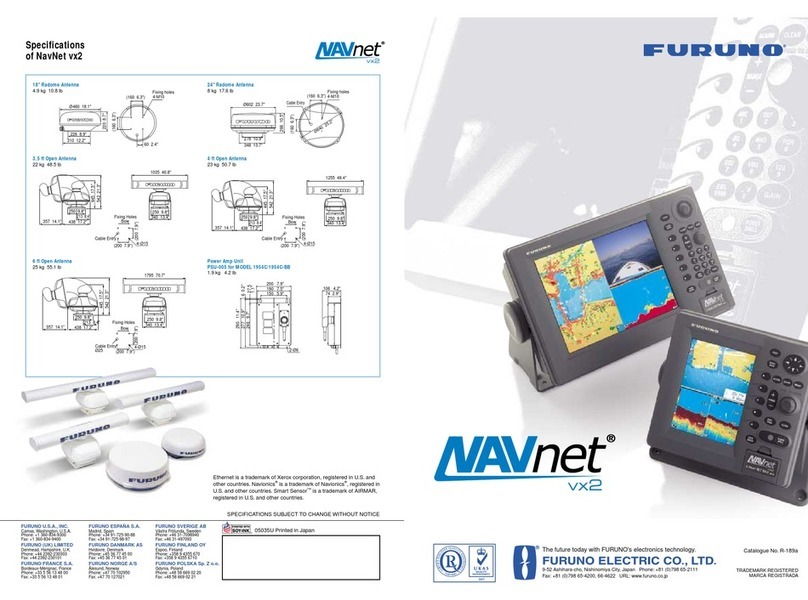
The FURUNO Model 1933C is an integrated navigation system. The
system integrates radar, differential global positioning system (DGPS), a
chart plotter, depth sounder, and a fluxgate compass. The system is
commercially available from FURUNO Electric Company as the NavNet®
system and is referred to by the USCG as the Scalable Integrated
Navigation System (SINS). The SINS package is the standard navigation
system onboard the USCG 25-ft RB-S, 41-ft UTB and the 47-ft MLB.
This job aid was prepared by Performance Systems Branch, Boat Forces
Center, and BM "A" School staff at TRACEN Yorktown, VA. Special
thanks go out to the Performance Technology Center for their pre-design
analysis work.
Performance Systems Branch
Training Center Yorktown
January 2010

3
Table of Contents
SINS Display Unit Controls
Overview of Display Unit Controls 5
Soft Keys 6
Trackball 6
Operational Setup
EnergizingtheSINS 7
Select Screen Display Mode 8
Adjust Display Brilliance and Panel Brilliance 9
Select the Hue 10
Man Overboard Procedures 11
EraseaMOBMark 12
AnchorWatchAlarm 13
SelectDataBoxes 14
SecuringtheSINS 15
Radar Operation
Transmitting 16
Tuning the Radar 17
AdjustingtheGain 18
AdjustingtheRange 19
RadarPresentationMode 20
Radar Presentation Mode Figures 21
Manually Acquire Target on Radar 22
Automatically Acquire Target on Radar 23
Measure Range by Range Rings 24
Measure Range by Cursor 25
Measure Range by VRM 26
Measuring Bearing 27
ReducingNoiseInterference 28
Rejecting Radar Interference 29
ZoominonTarget 30
Manual Shift Picture 31

4
Table of Contents
Automatic Shift Picture 32
Measure Range and Bearings between Two Targets 33
Head-On Situation Radar Display 34
Crossing Situation Radar Display 36
Overtaking Situation Radar Display 38
Plotter Operation
Presentation Modes 40
Shifting the Display 41
Chart Scales 41
Waypoints 41
Entering a Waypoint at Ownship Position 41
Entering a Waypoint by Cursor 42
Entering a Waypoint by Range and Bearing 43
Entering a Waypoint into the Waypoint List 45
Editing a Waypoint in the Waypoint List 47
SettingPlotterAlarms 49
SettingCrossTrackErrorAlarm 50
Routes
Creating Routes 51
Selecting the Route to Follow 52
Entering a Waypoint with the Cursor 53
Removing a Waypoint from the Route List 53
Stop Recording Waypoints and Save the Route 54
Erasing Routes 54
Navigating to a Quick Point 55
Navigating to a Single Quick Point 55

5
SINS DISPLAY UNIT CONTROLS
O
Ov
ve
er
rv
vi
ie
ew
w
The radar, video plotter, depth sounder, and chart systems are
operated with the controls of the display unit (figure 1) and the remote
controller.
Ten keys are labeled, and they provide the function shown on their
labels. The five soft keys provide various functions according to the
current operating mode. The [ENTER] knob mainly functions to
register selections on the menu and adjust the electronic bearing line
(EBL), variable range marker (VRM), and gain.
The trackball’s main function is to move the cursor across the screen.
When you correctly execute an operation, the unit generates a beep.
Invalid operation causes the unit to emit three beeps.

6
SINS DISPLAY UNIT CONTROLS
S
So
of
ft
t
K
Ke
ey
ys
s
|
|
T
Tr
ra
ac
ck
kb
ba
al
ll
l
Soft Keys:
The function of the five soft keys (figure 2) changes according to the operation. Their labels for their current functions are shown on the screen to the left
of the keys.
To hide or show the soft keys, press the [HIDE/SHOW] key. Each press of the key shows preset soft keys, user function keys, or turns off navigation
information (at the top of the screen).
Trackball:
The trackball functions to shift the cursor (figure 3), and is used for measurement of range and bearing to a location (radar) and latitude and longitude
position (plotter). Roll the trackball to shift the cursor. The cursor moves in the direction of trackball rotation.

7
OPERATIONAL SETUP
E
En
ne
er
rg
gi
iz
zi
in
ng
g
t
th
he
e
S
SI
IN
NS
S
Each boat type has a different breaker panel configuration to energize the system’s electrical circuit. Once the circuit is energized, complete the following
steps:
Energize SINS unit on your vessel by energizing the DGPS Circuit Breakers on
the vessel. A beep will sound and the unit will proceed automatically in its startup
performance test check.
Note: DGPS GP-37 must be turned on first BEFORE the Furuno NavNet is
turned on.
Press DGPS/Heading Sensor [POWER] key.
Note: A beep will sound and the unit will proceed automatically in its startup
performance test check.
Press the [POWER/BRILL] key to turn the unit on.
Note: The first time you turn on the power (or any time the power is applied after
a memory reset) you are asked if you want to start in the simulation mode which
provides simulated operation of the equipment. Push the [ENTER] knob to start
the simulation mode, or press the [CLEAR] key to start normal operation.
Note: A beep sounds and the equipment proceeds in the sequence shown
below, displaying product information, startup test results, and the chart usage
disclaimer. The startup test will check the internal ROM, RAM, internal battery
and backup data functions for proper operation and display the results for each
as OK or NG (No Good). If NG appears, an appropriate message appears on the
screen. For any NG, try to press any key to go to the chart disclaimer screen,
and then perform the diagnostic test. The magnetron takes from 1-2 minutes and
30 seconds (depending or radar model) to warm up before the radar can be
operated. The time remaining to complete the warm up of the magnetron is
counted down and displayed at the center of the display screen. You may press
any key at the chart disclaimer screen to show the last-used display feature or
wait several seconds to let the equipment do it for you.
Press Fathometer RD-30 [POWER] key.
Note: A beep will sound and unit will proceed automatically in its startup
performance test check.
1
2
3
4
2
3
4

8
OPERATIONAL SETUP
S
Se
el
le
ec
ct
t
S
Sc
cr
re
ee
en
n
D
Di
is
sp
pl
la
ay
y
M
Mo
od
de
e
If you have an installed radar, navigator, network sounder, and external video source (video recorder, etc., an optional PIP board is required), six full-
screen displays are available: plotter, radar, echo sounder, nav data, external video, and overlay. In addition to the full-screen display, you can divide the
screen into halves or into thirds to show two or three sets of images on a combination display. The overlay screen options are radar plus plotter.
Press [DISP] key to show the display selection window. The icons of modes not
available are marked with an "X."
Turn [ENTER] knob and push to select a basic display screen or hot page screen.
Select PLOTTER option using [ENTER] knob and press to set with chart plot on
left.
Note: Unit should be in SPLIT screen with Chart Plot on left. This is important
because when you hold the Man Overboard (MOB) key, the screen will enlarge
with whatever is on the left side of the screen.
Turn the [ENTER] knob to select display desired.
Select SPLIT option using [ENTER] knob and press to set.
Note: Unit should be in SPLIT screen with Chart Plot on left. This is important
because when you hold the Man Overboard (MOB) key, the screen will enlarge
with whatever is on the left side of the screen.
Press the [ENTER] knob to finish.
1
2
3
4
5
6

9
OPERATIONAL SETUP
A
Ad
dj
ju
us
st
t
D
Di
is
sp
pl
la
ay
y
B
Br
ri
il
ll
li
ia
an
nc
ce
e
a
an
nd
d
P
Pa
an
ne
el
l
B
Br
ri
il
ll
li
ia
an
nc
ce
e
Press [POWER/BRILL] key. A set of soft keys for adjustment of brilliance and
hue appear.
Press the DISPLAY BRILL or PANEL BRILL soft keys as appropriate.
An adjustment window appears at the bottom of the screen. This window shows
the name of the item selected for adjustment plus current brilliance level, by bar
graph.
Note: This equipment does not have a contrast control.
Adjust brilliance using [ENTER] knob. Clockwise to raise the setting or
counterclockwise to decrease it, and then press to set. You may also use the soft
key pressed at step 2. Eight levels of display brilliance and panel brilliance are
available.
Note: If the unit is turned off with minimum brilliance, the screen will be dark at
the next power-up. Press the [POWER/BRILL] key consecutively to adjust the
brilliance.
Select the RETURN soft key to finish.
1
2
3
4
5
3
2

10
OPERATIONAL SETUP
S
Se
el
le
ec
ct
t
t
th
he
e
H
Hu
ue
e
Press [POWER/BRILL] key momentarily.
Press the HUE soft key to show the hue setting window.
Note: When using the overlay screen, the ownship track will be hidden if the
radar background and ownship track are blue and the "MANUAL SET" hue
setting is used. In this case, set HUE to other position and then return to
"MANUAL" to show the ownship track in black.
Operate the trackball to select hue desired, referring to the table below.
MANUAL SET follows the color settings on the CHART DETAILS menu for the
plotter and the RADAR DISPLAY SETUP menu for the radar.
Night Day Twilight
Characters Red Black Green
Radar ring Red Green* Green*
Radar echo Orange Red Yellow
Background Black White Blue
Landmass (plotter) Light Yellow Yellow Light-Yellow
Select the RETURN soft key to finish.
1
2
3
4

11
OPERATIONAL SETUP
M
Ma
an
n
O
Ov
ve
er
rb
bo
oa
ar
rd
d
P
Pr
ro
oc
ce
ed
du
ur
re
es
s
The MOB (Man Overboard) mark functions to mark man overboard position.
You can inscribe this mark from any mode, except while playing back data or
conducting any test.
Note: This function requires position data.
Press and hold down the [SAVE/MOB] key for about 3 seconds when someone
falls overboard.
Note: The display shows the waypoint number being saved (youngest empty
waypoint number, 001-999) followed by the MOB confirmation window.
Press the [ENTER] knob to select the MOB position as the destination, or press
the [CLEAR] key to only mark current ship’s position as a waypoint.
Note: If you select the MOB position as destination or press [CLEAR] key to only
mark current ship’s position as a waypoint, a full-screen radar, plotter, or overlay
appears depending on the left side of the display.
(cont.)
1
2

12
OPERATIONAL SETUP
M
Ma
an
n
O
Ov
ve
er
rb
bo
oa
ar
rd
d
P
Pr
ro
oc
ce
ed
du
ur
re
es
s
(
(c
co
on
nt
t.
.)
)
Range and bearing to the MOB position are shown in the MOB data box.
Note: When using 3-second MOB mode, display will shift to the device on the
left side of the display (Plotter or Radar). The MOB mark "MOB" appears at the
MOB position and a light-blue line runs between it and current position. This line
shows the shortest course to the MOB position.
To Erase a MOB Mark:
You must first erase its corresponding waypoint. Place the cursor on the MOB
mark, then press the [CLEAR] key followed by pushing the [ENTER] knob to
erase the waypoint. Then, repeat to erase the MOB mark.
3
3

13
OPERATIONAL SETUP
A
An
nc
ch
ho
or
r
W
Wa
at
tc
ch
h
A
Al
la
ar
rm
m
Press the [ALARM] key to open the alarm menu.
Use the trackball to select ANCHOR WATCH ALARM.
Press the EDIT soft key to open the anchor alarm window: ANCHOR WATCH
ALARM.
Use the trackball to select ON. This will not show on the screen.
Use the trackball and the alphanumeric keys to enter alarm setting: Operate the
trackball to select digit; use the alphanumeric keys to enter value. The available
anchor watch setting is 0.001 to 9.999 miles.
Press the ENTER soft key or push the [ENTER] knob to register setting. This
step is invisible.
Press the [ALARM] key to finish.
Note: If the arrival alarm range is changed, turn off the anchor watch alarm and
then turn it on again to give priority to the anchor watch alarm.
1
2
3
4
5
3
6
7

14
OPERATIONAL SETUP
S
Se
el
le
ec
ct
t
D
Da
at
ta
a
B
Bo
ox
xe
es
s
Operate trackball and place cursor inside a data box you wish to move.
Press [ENTER] knob and the cursor enters the box and changes to a hand.
Press the knob again and the hand changes to a fist. The data box is now
draggable.
Note: Move the cursor over the box; then clear to remove.
Operate the trackball and drag the data box to its desired location.
CAUTION
Data boxes can cover up information and should be used sparingly.
If a data box is obscuring a desired object, you may temporarily
erase the box by setting D. Box to OFF.
Press [ENTER] knob to set data box in place.
1
2
3
4
5

15
OPERATIONAL SETUP
S
Se
ec
cu
ur
ri
in
ng
g
t
th
he
e
S
SI
IN
NS
S
Press GPS Navigation [POWER] key until the screen goes dark.
Press Radar/Display [POWER/BRILL] key until the screen goes dark.
Press Fathometer [POWER] key until the screen goes dark.
Note: A 3-second countdown will be displayed on the screen.
Place hard cover over LCD screen.
1
2
3
4

16
RADAR OPERATION
T
Tr
ra
an
ns
sm
mi
it
tt
ti
in
ng
g
Confirm that the network radar is plugged in.
Press the [DISP] key to select a radar display.
Press the [POWER/BRILL] key momentarily.
Press the RADAR STBY soft key to highlight TX on its label.
Press the RETURN soft key.
Standby Mode:
When the radar picture is not required, but you want to keep it in a state of readiness, press the RADAR TX soft key to highlight STBY on its label.
1
2
3
4
5

17
RADAR OPERATION
T
Tu
un
ni
in
ng
g
t
th
he
e
R
Ra
ad
da
ar
r
Press the [MENU] key to display the main menu.
Press the RADAR DISPLAY SETUP soft key.
Select TUNING and then press the EDIT soft key.
Select AUTO (manual) setting.
Note: Radar should remain in AUTO Tune and NOT Manual.
Press the [MENU] key to close menu.
1
2
3
4
5
1
3
2

18
RADAR OPERATION
A
Ad
dj
ju
us
st
ti
in
ng
g
t
th
he
e
G
Ga
ai
in
n
Depress [GAIN] key.
Depress GAIN soft key to show the gain sensitivity setting window.
Use trackball to select Auto Rough, Auto Moderate, Auto Calm, or Manual, as
appropriate.
Note: For normal operation, recommend Auto-Set (Moderate). If Manual setting
selected, go to 24-mile range and increase Gain until background speckle is
seen on the farthest edge.
Select an Auto option according to the sea state.
For manual adjustments, rotate [ENTER] knob to adjust, while observing radar
echo.
Note: Use [ENTER] knob to manually adjust to the ideal manual range of
between (30-40) and press return.
Press the [GAIN] key on the front panel or the RETURN soft key to finish.
1
2
3
4
5
6

19
RADAR OPERATION
A
Ad
dj
ju
us
st
ti
in
ng
g
t
th
he
e
R
Ra
an
ng
ge
e
The range setting determines the size of the area (in nautical miles) that will appear on your display. In addition, the range setting will also automatically
adjust the range ring interval so that accurate range measurements may be made while operating on any range setting. The range, range ring interval,
and pulse length appear at the top left-hand corner of the display.
Press the [RANGE (+ or - )] key to change the range scale.
Note: Range and scale are used interchangeably.
Radar range/plotter display will require constant adjustment due to operational
environment.
Range Scales (nm):
Range 0.125 0.25 0.5 0.75 1 1.5 2 3 4 6 8 12 16 24 36 48
Ring
Interval 0.0625 0.125 0.125 0.25 0.25 0.5 0.5 1 1 2 2 3 4 6 12 12
No. of
Rings 2 2 4 3 4 3 4 3 4 3 4 4 4 4 3 4
1
2

20
RADAR OPERATION
R
Ra
ad
da
ar
r
P
Pr
re
es
se
en
nt
ta
at
ti
io
on
n
M
Mo
od
de
e
If not displayed, press the [HIDE/SHOW] key to show the radar soft keys.
Press RADAR DISPLAY soft key to show the soft keys.
Press the desired MODE soft key. Each pressing of the key changes the
presentation mode and the presentation mode indication in the sequence of
North-up, True Motion, Head-up, and Course-up.
Function Indicator on display Soft key label
North-up N-UP NTH UP
Head-up H-UP HD UP
Course-up C-UP CSE UP
Note: Heading data is required for modes other than head-up.
Press the RETURN soft key to finish. Note: When heading data is lost, the
presentation mode automatically goes to Head-up; the heading indication at the
screen top shows "- - -.-" and the audio alarm sounds. Press the [ALARM]
key. "HEADING DATA MISSING" appears. Restore compass signal to show
heading indication. Use the MODE soft key to select presentation mode if
necessary. The audio alarm may be silenced with the [CLEAR] key.
1
2
3
4
Table of contents
Other Furuno Car Navigation System manuals