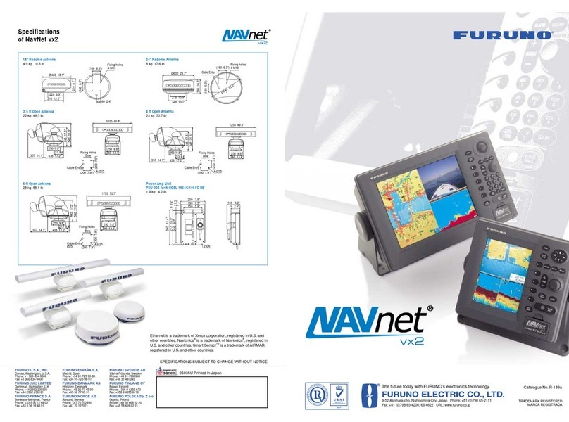
Furuno ENVISION AR-100M User manual

AR NAVIGATION SYSTEM
AR-100M
OPERATOR'S MANUAL
www.furuno.com
Model

7KHSDSHUXVHGLQWKLVPDQXDO
LVHOHPHQWDOFKORULQHIUHH
࣭)85812$XWKRUL]HG'LVWULEXWRU'HDOHU
$VKLKDUDFKR
1LVKLQRPL\D-$3$1
$ 6(3
3ULQWHGLQ-DSDQ
$OOULJKWVUHVHUYHG
% '(&
3XE1R 20(%
5()8 $50

i
IMPORTANT NOTICES
General
• This manual has been authored with simplified grammar, to meet the needs of international users.
• The operator of this equipment must read and follow the instructions in this manual.
Wrong operation or maintenance can void the warranty or cause injury.
• Do not copy any part of this manual without written permission from FURUNO.
• If this manual is lost or worn, contact your dealer about replacement.
• The contents of this manual and the equipment specifications can change without notice.
• The example screens (or illustrations) shown in this manual can be different from the screens you
see on your display. The screens you see depend on your system configuration and equipment
settings.
• Save this manual for future reference.
• Any modification of the equipment (including software) by persons not authorized by FURUNO will
void the warranty.
• The following concern acts as our importer in Europe, as defined in DECISION No 768/2008/EC.
- Name: FURUNO EUROPE B.V.
- Address: Ridderhaven 19B, 2984 BT Ridderkerk, The Netherlands
• All brand, product names, trademarks, registered trademarks, and service marks belong to their
respective holders.
• Windows is either registered trademarks or trademarks of Microsoft Corporation in the United
States and/or other countries.
How to discard this product
Discard this product according to local regulations for the disposal of industrial waste. For disposal
in the USA, see the homepage of the Electronics Industries Alliance (http://www.eiae.org/) for the
correct method of disposal.
How to discard a used battery
Some FURUNO products have a battery(ies). To see if your product has a battery, see the chapter
on Maintenance. If a battery is used, tape the + and - terminals of the battery before disposal to pre-
vent fire, heat generation caused by short circuit.
In the European Union
The crossed-out trash can symbol indicates that all types of batteries
must not be discarded in standard trash, or at a trash site. Take the
used batteries to a battery collection site according to your national
legislation and the Batteries Directive 2006/66/EU.
In the USA
The Mobius loop symbol (three chasing arrows) indicates that
Ni-Cd and lead-acid rechargeable batteries must be recycled.
Take the used batteries to a battery collection site according to
local laws.
In the other countries
There are no international standards for the battery recycle symbol. The number of symbols can in-
crease when the other countries make their own recycle symbols in the future.
Cd
Ni-Cd Pb

ii
SAFETY INSTRUCTIONS
Indicates a potentially hazardous situation which, if not avoided,
may result in minor or moderate injury.
Indicates a potentially hazardous situation which, if not avoided,
could result in death or serious injury.
WARNING
CAUTION
Warning, Caution Prohibitive Action Mandatory Action
WARNING
WARNING
Be sure to power each unit with
proper voltage.
Connection of an improper power supply
can cause fire or damage the equipment.
Turn the system off before cleaning
and doing maintenance.
Turn off the power immediately if you
feel the equipment is acting
abnormally.
If the equipment is hot to touch or is
emitting strange noises, turn the power
off immediately and contact your delaer
for advice.
CAUTION
Do not open the equipment unless
totally familiar with electrical circuits.
Only qualified personnel can work inside
the equipment.
Turn the power off before beginning
the installation.
Be sure both the system and all external
devices are turned off. Sudden surge of
power could damage the equipment.
The operator and installer must read the applicable safety instructions before attempting to operate or
install the equipment.
Do not disassemble or modify the
equipment.
Fire, electrical shock or serious injury
can occur.
Turn the power off immediately if the
equipment is emitting smoke or fire.
Fire or electrical shock can result if the
power is left on.
The mounting location must satisfy
the operating temperature range of the
equipment.
Do not install the equipment where it
may get wet from rain or water splash.
Water can cause fire or electrical shock,
or damage the equipment.
Do not operate the equipment with wet
hands.
Electrical shock can result.
Do not depend on one navigation
device for the navigation of the vessel.
Always check your position against all
available aids to navigation, for the safety
of vessel and crew.
Do not connect/disconnect a cable
from the main PC while turning the
power on.

iii
TABLE OF CONTENTS
FOREWORD.................................................................................................................... v
SYSTEM CONFIGURATION .......................................................................................... vi
EQUIPMENT LIST ......................................................................................................... vii
1. OPERATION ..........................................................................................................1-1
1.1 What is AR Navigation System?.................................................................................1-1
1.2 Controls Overview ......................................................................................................1-2
1.3 How to Turn the System On/Off .................................................................................1-2
1.4 Display Overview........................................................................................................1-3
1.5 TVI (Top View Indicator).............................................................................................1-5
1.6 How to Change the Base Color ..................................................................................1-6
1.7 How to Set the CPA and TCPA Thresholds ...............................................................1-7
1.8 How to Customize the Graphics Object......................................................................1-7
1.8.1 How to show/hide the azimuth scale ..............................................................1-7
1.8.2 How to show/hide the heading guide .............................................................1-8
1.8.3 How to show/hide the horizon line..................................................................1-8
1.8.4 How to customize the grid lines......................................................................1-9
1.8.5 How to show/hide the target shape ................................................................1-9
1.8.6 How to customize target information ............................................................1-10
1.8.7 How to customize the route display..............................................................1-12
1.8.8 How to show/hide the waypoint information .................................................1-12
1.8.9 How to show/hide the ENC chart objects .....................................................1-13
1.9 User Charts ..............................................................................................................1-14
1.9.1 How to import user charts created on the ECDIS ........................................1-14
1.9.2 How to show/hide the user charts ................................................................1-16
1.9.3 How to adjust area object transparency .......................................................1-16
1.9.4 How to customize no-go area objects ..........................................................1-16
1.9.5 How to adjust the text size for label objects .................................................1-17
1.10 How to Adjust the Video Image Brilliance.................................................................1-17
1.11 How to Adjust the Video Image Position ..................................................................1-18
2. INSTALLATION AND INITIAL SETTINGS............................................................2-1
2.1 Mounting.....................................................................................................................2-1
2.1.1 Main PC..........................................................................................................2-1
2.1.2 PoE adapter ...................................................................................................2-3
2.1.3 IP camera .......................................................................................................2-4
2.1.4 Trackball.........................................................................................................2-6
2.2 Wiring .........................................................................................................................2-7
2.2.1 Main PC..........................................................................................................2-7
2.2.2 PoE adapter ...................................................................................................2-9
2.2.3 IP camera .....................................................................................................2-10
2.3 Initial Settings ...........................................................................................................2-11
2.3.1 How to login as a service technician ............................................................2-11
2.3.2 Initial settings for the IP camera ...................................................................2-12
2.3.3 How to setup the CCRP ...............................................................................2-13
2.3.4 How to setup the bow position .....................................................................2-13
2.3.5 How to setup the data source for the pitch/roll data .....................................2-14
2.3.6 How to setup the data source for the TT data ..............................................2-15
2.3.7 How to enter the IP address of the route server...........................................2-16
2.3.8 How to enter the IP address of the ENC chart server ..................................2-16
2.3.9 Settings for connected equipment................................................................2-17
2.4 Operation Check.......................................................................................................2-18
TABLE OF CONTENTS
iv
3. MAINTENANCE .....................................................................................................3-1
3.1 Service and Repair..................................................................................................... 3-1
3.2 Warranty Period ......................................................................................................... 3-1
3.3 Recommended Replacement Period ......................................................................... 3-1
3.4 Troubleshooting ......................................................................................................... 3-2
3.5 Error Code/Error Message......................................................................................... 3-3
3.6 How to Restore Default Settings ................................................................................ 3-7
3.7 System Information .................................................................................................... 3-8
3.7.1 How to show the system information ............................................................. 3-8
3.7.2 Sentence monitor window..............................................................................3-9
3.8 How to Perform the Virus Scan................................................................................ 3-10
3.9 How to Update the AR Navigation System Application............................................ 3-11
3.10 How to Update Virus Definition ................................................................................ 3-12
3.11 How to Update the Operating System...................................................................... 3-14
3.12 How to Show Software Information.......................................................................... 3-15
APPENDIX 1 MENU TREE .......................................................................................AP-1
SPECIFICATIONS .....................................................................................................SP-1
PACKING LISTS.......................................................................................................... A-1
INTERCONNECTION DIAGRAM ................................................................................ S-1
INDEX..........................................................................................................................IN-1

v
FOREWORD
Congratulations on your choice of the FURUNO AR-100M AR Navigation System. We are confi-
dent you will see why the FURUNO name has become synonymous with quality and reliability.
Since 1948, FURUNO Electric Company has enjoyed an enviable reputation for quality marine
electronics equipment. This dedication to excellence is furthered by our extensive global network
of agents and dealers.
This equipment is designed and constructed to meet the rigorous demands of the marine environ-
ment. However, no machine can perform its intended function unless operated and maintained
properly. Please carefully read and follow the recommended procedures for operation and main-
tenance.
We would appreciate hearing from you, the end-user, about whether we are achieving our goal.
Thank you for considering and purchasing FURUNO equipment.
Cyber Security Notes
Keep in mind the following points to protect the AR navigation system from viruses.
• The AR navigation system is equipped with anti-virus software. The virus definitions and related
files must be kept up-to-date. The operator is solely responsible for updating the virus definition.
For how to update the virus definitions, see section 3.10.
• The PC and USB flash memory used to download and store an update file (for user chart file,
virus definition, etc.) may be infected with a virus. Check the PC and the USB flash memory for
viruses with a virus checker BEFORE you connect the USB flash memory to the AR navigation
system.
• The main PC must be located in a high physical security area.
• DO NOT connect the AR navigation system and HUB-3000 to an external network, including
other shipborne LAN.

vi
SYSTEM CONFIGURATION
*: Performance after corrections to pitch, roll and yaw errors may vary, depending on the specifi-
cations of the connected equipment.
Monitor
100-240 VAC
Main PC PoE Adapter IP Camera
: Standard supply
: Local supply
Trackball
Intelligent HUB
HUB-3000
100-230 VAC
1Ø, 50/60Hz
ECDIS
(FMD-3200/3300)
Radar
(FAR-3000/FAR-2××7/FAR-2××8)
Radar Sensor (Antenna Unit)
Satellite Speed Log* (GS-100) or
SATELLITE COMPASS
TM
* (SC-33/SC-70/SC-130)
Gyrocompass
GPS (GP-150/GP-170)
AIS (FA-150/FA-170)
100-240 VAC

vii
EQUIPMENT LIST
Standard supply
Name Type Code No. Qty Remarks
Main PC
(Fanless Box PC)
eBOX100-312-FL-
N3350 -1
With AC adapter (3 m) and
mounting kit
IP Camera GV-EBX2100 - 1
PoE Adapter GV-PA191 - 1 With AC adapter (1.8 m)
Trackball K72337JP - 1 With 1.5 m USB cable
ENC Dongle ENC-KEY - 1
HDMI Cable DH-HD14E50/RS 000-197-075-10 1 10 m cable between main PC
and monitor
LAN Cable
P5E-4PTX-BL L=10M 000-164-637-10 2
10 m cable between:
• HUB-3000 and main PC
• IP camera and PoE adapter
P5E-4PTX-BL L=2M 000-164-634-10 1 2 m cable between PoE adapt-
er and main PC
USB Cable KU-EN5K 000-197-073-10 2
5 m cable between:
• USB flash memory and
main PC
• Trackball and main PC
Bracket TB-109 000-197-072-10 1 For installing IP camera
Adhesive Rubber QL-53CL 000-197-074-10 1 For installing PoE adapter

EQUIPMENT LIST
viii
This page is intentionally left blank.

1-1
1. OPERATION
1.1 What is AR Navigation System?
The AR (Augmented Reality) navigation system is designed to assist in collision avoid-
ance and increase safety of life at sea by giving the operator an increased level of sit-
uational awareness around the vessel.
The AR navigation system can overlay the following navigation data on the actual vid-
eo image in front of a vessel captured by the IP camera.
• Azimuth information from gyrocompass
• AIS data from AIS transponder (example: FURUNO FA-170)
• TT data from radar (example: FURUNO FAR-3××0, FAR-2××8)
• Route, To waypoint, user chart and ENC chart symbols from ECDIS (FURUNO
FMD-3200/3300)
The system keeps the AR objects aligned with the actual targets, compensating for
roll, pitch and yaw.
Note 1: Do not solely rely on the AR navigation system to navigate the vessel. Always
check your position against all available aids to navigation, for the safety of vessel and
crew.
Note 2: An ENC dongle is necessary to share the ENC charts from the ECDIS. The
ENC dongle is supplied with the AR navigation system. Keep the ENC dongle con-
nected to one of the USB ports on the main PC while using the AR navigation system.
For the video introducing the AR-100M,
scan to visit our YouTube channel.
For the video of the AR stabilization,
scan to visit our YouTube channel.
Display example for the AR navigation system
XXXXXX
XXXXXXXXX XXXXXXXXXXXX

1. OPERATION
1-2
1.2 Controls Overview
You can control almost all aspects of your AR navi-
gation system from the trackball. The figure to the
right and the table below show an overview of the
trackball with a brief description of the controls.
Standards used in this manual
Unless noted otherwise, “click” means to put the cursor on a object and press the left
button on the trackball.
1.3 How to Turn the System On/Off
The power button for the system is located on the front panel of the main PC.
Note: When you turn the system on/off, keep in mind the following points:
• Supply power to the IP camera BEFORE turning on the AR navigation system. The
video image may not appear if the IP camera is not powered first. If the video image
does not appear, restart the AR navigation system.
• Lightly press the power button. If the power button is pressed too firmly, the button
may get caught on the chassis.
• Do not turn the system off at the switchboard or breaker. The unit may be damaged.
No. Name Description
1 Left button Select a highlighted object or menu item.
2 Right button No function.
3 Scroll ring • Scrolls the menu.
• Zooms in/out at cursor location.
4 Trackball Moves the cursor.
2
1
3
4
Power button
LED indicators

1. OPERATION
1-3
How to turn the system on
To turn the system on, press the power button. After pressing the power button, the
LED on the main PC lights up and the system begins its startup process. When the
startup process is completed, the following message appears. Confirm the message,
then click the [OK] button to close the message.
When connecting to the IP camera, the following message appears at the center of
the screen. Connecting process can take up to approximately one minute. After con-
necting with the IP camera, the AR navigation system screen appears automatically
on the display.
Note: When the user chart file has be imported, the message
shown in the figure to the right appears. For how to import the
user chart file, see subsection 1.9.1.
How to turn the system off
To turn the system off, press the power button again.
1.4 Display Overview
No. Name Description
1Menu button Opens/closes the main menu.
2Working indicator Rotates clockwise when the system is working correctly. Stops rotat-
ing when the system is frozen or malfunctioning.
1 2 4
5
6
7
7
8
8
9
9
1.5NM
10:45
71.3°
11
11
12
12
XXXXXXX 3.0NM
13
13
14
14
15
15
10
10
3
17
17
18
18
16
16
19
19
FURUNO FURUNO
XXXXXXXXX

1. OPERATION
1-4
3Main menu The main menu contains customizing options for this equipment. To
open/close the menu, click the menu button. You can also close the
main menu by clicking the video image.
4Range Shows the current display range in use for the AR navigation system.
5Range control button Adjusts the display range in use for the AR navigation system. The
symbols on the AR navigation screen and TVI (Top View Indicator)
change according to the display range. Click the button to increase
the range, or click the button to reduce the range.
6Presentation mode
button
Toggles between head-up and north-
up presentation modes for the TVI.
The indication on the button changes
according to the presentation mode.
• [H-UP] (Head Up): Displays the symbols with the heading line of
own ship at the top of the TVI. The heading line and the direction of
the field of view are fixed, and the symbols rotate according to the
heading.
• [N-UP] (North Up): True north (0°) is at the top of the TVI. The head-
ing line and the direction of the field of view rotate according to the
heading.
7TVI (Top View Indica-
tor)
Displays the TT and AIS target’s location in a circle about own ship.
For details, see section 1.5.
8Azimuth scale Provides an estimate of the bearing to a target.
9Heading guide You can estimate the heading of own ship, by reading the point at
which the heading guide intersects the azimuth scale.
Note: When the IP camera position is offset from the ship’s center, the
heading guide is not aligned with the ship’s bow on the video image.
10 Horizon line Indicates the horizon, and is used to adjust the video image position.
Normally, hide the horizon line. For how to show/hide the horizon line,
see subsection 1.8.3.
11 Waypoint information Display the information (course to the next waypoint, time to go, dis-
tance) for the To waypoint on the route.
12 No-go area Indicates the area where the vessel is not allowed to go. You can
show or hide the visible wall for the no-go area. See subsection 1.9.4.
When you hide the visible wall, the no-go area is drawn only with a
line.
13 User chart label Indicates the user chart input from ECDIS.
14 Selective marker Click the marker to show the TT or AIS target information. The figure
below shows the appearance of the AIS and TT symbols.
When a AIS or TT target is evaluated to be an attentional target, its
symbol is shown in the designated color (yellow, orange or red). For
how to change the color, see section 1.7.
15 Route leg Shows the monitored route leg that is shared with the ECDIS.
16 Target shape The target shape function overlays a ship graphic and buoy graphic
on respective AIS targets and buoys. This is useful when AIS targets
and buoys are not visible to the eye because of darkness or fog. For
how to show/hide the target shape, see subsection 1.8.5.
No. Name Description
H-UP N-UP
Click
TT symbolAIS symbol
SelectedUnselected SelectedUnselected

1. OPERATION
1-5
1.5 TVI (Top View Indicator)
The TVI displays the TT and AIS
target’s location in a circle about
own ship. The field of view on the
AR navigation system is filled in
gray. The area out of the field of
view is filled in black. When you
zoom in/out the screen (by the
scroll ring), the field of view on the
TVI also changes.
The AIS or TT target that is within
the range of the CPA/TCPA
threshold is shown in the desig-
nated color (yellow, orange or
red). If there is an attentional tar-
get in the out of field of view area,
the area flashes in the designated color. The color can be changed from the menu.
See section 1.7.
Range control
You can adjust the display range for the AR navigation system from the range control
button. The symbols on the AR navigation screen and TVI change according to the
display range. Click the button to increase the range, or click the button to reduce
the range.
17 Main target informa-
tion frame
Shows navigation information for the target chosen with the selective
marker. To close the frame, click the selective marker again to dese-
lect the marker. You can customize the information to be shown in the
frame. See subsection 1.8.6
18 Appended target in-
formation frame
Click the main target information frame to show the appended target
information frame. To close the frame, click the main target informa-
tion frame again. You can customize the information to be shown in
the frame. See subsection 1.8.6.
19 Grid Grid lines can be shown on the display, and are available in two types.
• [Own]: Shows the grid lines based on the current IP camera posi-
tion. Grid lines are fixed.
• [World]: Shows the grid lines based on the IP camera position when
the AR-100M application is started. Grid lines move according to
the ship’s movement.
For how to change the mode or hide the grid, see subsection 1.8.4.
No. Name Description
Symbols
(TT or AIS target)
Range control
button
Presentation
mode button
Out of field of view
(filled in black)
Heading line
Field of view
(filled in gray) Range
For the attentional target indication in the out-of-view
area, scan to visit our YouTube channel.
For the change of the AR navivation screen due to the
range switching, scan to visit our YouTube channel.

1. OPERATION
1-6
Presentation mode
To change the presentation mode, click the presentation mode at the top right of the
screen.
The following presentation modes are available with the TVI:
• [H-UP] (Head Up): Displays the symbols with the heading line of own ship at the top
of the TVI. The heading line and the direction of the field of view are fixed, and the
symbols rotate according to the heading.
• [N-UP] (North Up): True north (0°) is at the top of the TVI. The heading line and the
direction of the field of view rotate according to the heading.
Symbols
The following table shows the symbols used in the TVI.
Note 1: The normal target color depends on the base color setting. See section 1.6.
Note 2: The attentional target color can be changed from the menu. See section 1.7.
1.6 How to Change the Base Color
You can change the base color for the AR navigation system screen. The base color
is applied to the following items:
1. Click the menu button to open the main
menu.
2. Click [Base Color].
3. Click an appropriate checkbox to select the
base color.
4. Close the main menu.
Without HDG/COG With HDG/COG
AIS (HDG > COG)
TT (COG)
• Main menu text and buttons • Waypoint text • User chart
(other than no-go area)
• Target information text and frame* • Route leg • Horizon line
• Grid • ENC chart • Azimuth scale
• Symbols* and buttons for TVI • Working indicator • Target shape*
• Heading guide *: Does not include attentional targets.
H-UP N-UP
Click

1. OPERATION
1-7
1.7 How to Set the CPA and TCPA Thresholds
The AR navigation system continuously monitors the predicted range at the Closest
Point of Approach (CPA) and predicted time to CPA (TCPA) of each AIS and TT tar-
get. When the predicted CPA of any AIS or TT becomes smaller than the preset CPA
threshold and its predicted TCPA less than the preset TCPA threshold, the symbol
and target information color are changed to the designated color (yellow, orange or
red).
1. Click the menu button to open the main
menu.
2. Click [CPA/TCPA].
3. Adjust the slider bar for [CPA Threshold] to
change the CPA threshold.
4. Adjust the slider bar for [TCPA Threshold] to
change the TCPA threshold.
5. Click an appropriate checkbox of [Attentional Color] to select the color for the at-
tentional target.
6. Close the main menu.
1.8 How to Customize the Graphics Object
1.8.1 How to show/hide the azimuth scale
The azimuth scale is shown at the top of the screen. You can use the scale to estimate
the bearing of ship’s heading or a target. The azimuth scale rotates according to the
ship’s movement.
1. Click the menu button to open the main
menu.
2. Click [Graphics Object].
3. Click [Azimuth Scale].
4. Check the checkbox for [Visible] to show the
azimuth scale. If you want to hide the scale,
remove the check mark from the checkbox.
5. Adjust the slider bar for [Text Scale] to change the size of the text on the azimuth
scale.
6. Close the main menu.
Azimuth scale

1. OPERATION
1-8
1.8.2 How to show/hide the heading guide
You can estimate the heading of own ship, by reading the point at which the heading
guide intersects the azimuth scale.
1. Click the menu button to open the main
menu.
2. Click [Graphics Object].
3. Click [Heading Guide].
4. Check the checkbox for [Visible] to show the
heading guide. If you want to hide the head-
ing guide, remove the check mark from the
checkbox.
5. Close the main menu.
1.8.3 How to show/hide the horizon line
You can show the horizon line on the AR navigation system. If the horizon line is not
aligned with the horizon on the screen, adjust the position of the video image. See
section 1.11.
Note: The horizon line is used to adjust the video image position. Normally, hide the
horizon line.
1. Click the menu button to open the main
menu.
2. Click [Graphics Object].
3. Click [Horizon].
4. Check the checkbox for [Visible] to show the
horizon line. If you want to hide horizon line,
remove the check mark from the checkbox.
5. Close the main menu.
Heading guide
Horizon lineHorizon line

1. OPERATION
1-9
1.8.4 How to customize the grid lines
Grid lines can be shown in one of two methods.
• [Own]: Shows the grid lines based on the current IP camera position. Grid lines are
fixed.
• [World]: Shows the grid lines based on the IP camera position when the AR-100M
application is started. Grid lines move according to the ship’s movement.
Also, you can customize the grid pitch, number of grid cells and the transparency of
the grid lines.
1. Click the menu button to open the main
menu.
2. Click [Graphics Object].
3. Click [Grid].
4. Check the checkbox for [Visible] to show
the grid. If you want to hide the grid, remove
the check mark from the checkbox.
5. Check the radio button for [World] or [Own].
6. Adjust the slider bar for [Pitch], [Extension]
and [Density] as appropriate.
• [Pitch]: Adjust the pitch for the grid lines.
• [Extension]: Adjust the number of the grid cells.
• [Density]: Adjust the transparency of the grid lines.
7. Close the main menu.
1.8.5 How to show/hide the target shape
You can overlay the applicable target shape (graphic) on AIS targets and buoys. This
feature is useful for showing the AIS targets and buoys on the screen that are not com-
pletely visible because of darkness or fog.
Grid
Grid
Target shape = OFF Target shape = ON

1. OPERATION
1-10
The AR navigation system overlays the following target shapes according to the target
size and type.
1. Click the menu button to open the main
menu.
2. Click [Graphics Object].
3. Click [Target Shape].
4. Check the checkbox for [Visible] to show the
target shape. If you want to hide the target
shape, remove the check mark from the
checkbox.
5. Close the main menu.
1.8.6 How to customize target information
You can customize the contents in the main target information frame and appended
target information frame.
1. Click the menu button to open the main menu.
2. Click [Graphics Object].
3. Click [Target Information].
Buoy/Virtual buoy AIS target (boat) AIS target (tanker)
Main target information frameMain target information frame
Appended target information frameAppended target information frame
FURUNO XXXXXXXXX FURUNO
1
2
2
3
3
4
4
5
5
Table of contents
Other Furuno Car Navigation System manuals
Popular Car Navigation System manuals by other brands

Simrad
Simrad Maris ECDIS900 Operator's manual

GPS Designer international
GPS Designer international HN-2000 User manual and reference guide

Skoda
Skoda OCTAVIA owner's manual

Magellan
Magellan Maestro 3250 - Automotive GPS Receiver user manual

TeeJet Technologies
TeeJet Technologies Centerline 230BP Guidance

Panasonic
Panasonic Strada CN-GP50N Important information