Furuno SC-33 User manual

SATELLITE COMPASS
SC-33
OPERATOR'S MANUAL
www.furuno.com
Model


i
IMPORTANT NOTICES
General
• This manual has been authored with simplified grammar, to meet the needs of international users.
• The operator of this equipment must read and follow the descriptions in this manual. Wrong oper-
ation or maintenance can cancel the warranty or cause injury.
• Do not copy any part of this manual without written permission from FURUNO.
• If this manual is lost or worn, contact your dealer about replacement.
• The contents of this manual and equipment specifications can change without notice.
• The example screens (or illustrations) shown in this manual can be different from the screens you
see on your display. The screens you see depend on your system configuration and equipment
settings.
• Save this manual for future reference.
• Any modification of the equipment (including software) by persons not authorized by FURUNO will
cancel the warranty.
• The following concern acts as our importer in Europe, as defined in DECISION No 768/2008/EC.
- Name: FURUNO EUROPE B.V.
- Address: Ridderhaven 19B, 2984 BT Ridderkerk, The Netherlands
• All brand and product names are trademarks, registered trademarks or service marks of their re-
spective holders.
How to discard this product
Discard this product according to local regulations for the disposal of industrial waste. For disposal in
the USA, see the homepage of the Electronics Industries Alliance (http://www.eiae.org/) for the cor-
rect method of disposal.
How to discard a used battery
Some FURUNO products have a battery(ies). To see if your product has a battery, see the chapter
on Maintenance. Follow the instructions below if a battery is used. Tape the + and - terminals of bat-
tery before disposal to prevent fire, heat generation caused by short circuit.
In the European Union
The crossed-out trash can symbol indicates that all types of batteries
must not be discarded in standard trash, or at a trash site. Take the
used batteries to a battery collection site according to your national
legislation and the Batteries Directive 2006/66/EU.
In the USA
The Mobius loop symbol (three chasing arrows) indicates that Ni-Cd
and lead-acid rechargeable batteries must be recycled. Take the
used batteries to a battery collection site according to local laws.
In the other countries
There are no international standards for the battery recycle symbol. The number of symbols can in-
crease when the other countries make their own recycle symbols in the future.
Cd
Ni-Cd Pb

ii
SAFETY INSTRUCTIONS
Indicates a potentially hazardous situation which, if not avoided,
could result in death or serious injury.
Indicates a potentially hazardous situation which, if not avoided,
can result in minor or moderate injury.
Warning, Caution
Mandatory Action
Prohibitive Action
WARNING
Do not open the equipment.
Only qualified personnel should work
inside the equipment.
Do not disassemble or modify the
equipment.
Fire, electrical shock or serious injury can
result.
.
Safety instructions for the operator
Observe the following compass safe
distances to prevent interference to a
magnetic compass:
Standard
compass
Steering
compass
0.45 m 0.40 m
SC-33
Turn off the power at the switchboard
before beginning the installation.
Fire or electrical shock can result if the
power is left on.
Be sure that the power supply is
compatible with the voltage rating of the
equipment.
Connecting an incompatible power supply
can cause fire or damage the equipment.
The voltage rating appears on the inlet
of power.
WARNING
Safety instructions for the installer
Warning Label
A warning label is attached to the equipment.
Do not remove the label. If the label is missing
or illegible, contact a FURUNO agent or dealer
about replacement.
Name: Warning Label(1)
Type: 86-003-1011-3
Code No.: 100-236-233-10
CAUTION
WARNING
CAUTION
WARNING
To avoid electrical shock, do not
remove cover. No user-serviceable
parts inside.
Do not use high-pressure cleaners to
clean this equipment.
This equipment has the waterproof rating
outlined in the specifications, at the back
of this manual. However, the use of
high-pressure cleaning equipment can
cause water ingress, resulting in damage
to, or failure of, the equipment.
.

iLi
TABLE OF CONTENTS
FOREWORD ................................................................................................................. iv
SYSTEM CONFIGURATION ......................................................................................... v
1. MOUNTING ............................................................................................................. 1
1.1 Equipment Lists........................................................................................................... 1
1.2 Mounting Considerations ............................................................................................ 3
1.3 Mounting Procedure.................................................................................................... 8
2. WIRING ................................................................................................................. 10
2.1 NMEA 2000 Network Connection ............................................................................. 10
2.2 NMEA 0183 Network Connection ............................................................................. 11
2.2.1 How to connect the Cable Assembly (FRU-NMEA-NFF-R15/30)...................... 11
2.2.2 How to connect the Cable Replacement Kit (OP20-50) .................................... 12
2.2.3 How to secure and waterproof the cable connections ....................................... 15
3. ADJUSTMENTS.................................................................................................... 16
3.1 Initial Setting Menu.................................................................................................... 16
4. NMEA 2000 I/O DATA .......................................................................................... 21
4.1 Input Data.................................................................................................................. 21
4.2 Output Data............................................................................................................... 22
5. MAINTENANCE, TROUBLESHOOTING.............................................................. 25
5.1 Preventive Maintenance............................................................................................ 25
5.2 Troubleshooting ........................................................................................................ 25
MENU TREE ............................................................................................................AP-1
WHAT IS SBAS? .....................................................................................................AP-5
SPECIFICATIONS ................................................................................................... SP-1
PACKING LISTS........................................................................................................ A-1
OUTLINE DRAWING ................................................................................................. D-1
INTERCONNECTION DIAGRAM .............................................................................. S-1

iv
FOREWORD
A Word to the Owner of the SC-33
Congratulations on your choice of the FURUNO SC-33 Satellite Compass. We are confident you
will see why the FURUNO name has become synonymous with quality and reliability.
Since 1948, FURUNO Electric Company has enjoyed an enviable reputation for quality marine
electronics equipment. This dedication to excellence is furthered by our extensive global network
of agents and dealers.
This equipment is designed and constructed to meet the rigorous demands of the marine
environment. However, no machine can perform its intended function unless installed properly.
Please carefully read and follow the recommended procedures for installation.
Thank you for considering and purchasing FURUNO equipment.
Features
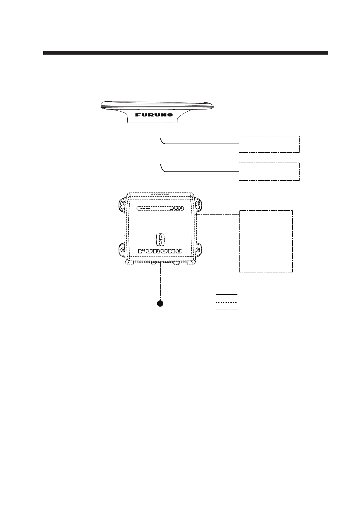
The SC-33 Satellite Compass outputs highly accurate heading, GNSS position data and speed
and motion data for AIS, Tracked Target (TT) radar, autopilots, etc. Data is output in NMEA 2000®
(NMEA2000 is a trademark of National Marine Electronic Association (the United States)) format,
and with connection of the optional interface unit the data can be converted to NMEA 0183 format.
Setting time is within three minutes and the follow-up performance is an excellent 45°/s.
• Heading accuracy of 0.4° RMS
• Perfect heading sensor for radar/TT, AIS, scanning sonar, etc.
• Outputs accurate heading, position, time, speed, course.
• Pitch and roll output in digital format for ship's motion correction
• A new Satellite Compass™ designed with FURUNO advanced GNSS kinematic technology.
• Data can be output in NMEA 2000 format
• Free from regular maintenance
• Aesthetically pleasing antenna fits nicely on recreational boats
• Outputs acceleration speed and angular velocity at installation
Software used in this product
This equipment uses the following open source software.
This product includes software to be licensed under the GNU General Public License (GPL) ver-
sion 2.0, GNU Lesser General Public Software License (LGPL) version 2.0, Apache, BSD and oth-
ers. The program(s) is/are free software(s), and you can copy it and/or redistribute it and/or modify
it under the terms of the GPL version 2.0 or LGPL version 2.0 as published by the Free Software
Foundation. Please access to the following URL if you need source codes.
https://www.furuno.co.jp/en/contact/cnt_oss_e01.html
Program No.
OS : 2051593-01.**
APL : 2051594-01.**
GNSS: 48505230**
** denotes minor modifications.

v
SYSTEM CONFIGURATION
SC-33
Satellite Compass
12-24 VDC
: Standard supply
: Optional supply
: Local supply
IF-NMEASC
INTERFACE UNIT
Video Plotter
Radar
Autopilot
Current Indicator
Scanning Sonar
Video Sounder
AIS
NavNet Series, etc,.
NMEA2000
NMEA0183
Marine Instrument
Junction Box
IF-NMEASC

1
1. MOUNTING
1.1 Equipment Lists
Standard supply
* See packing list at back of manual for details.
Name Type Code No. Qty Remarks
Satellite
Compass SC-33 - 1
Installation
Materials
CP20-04400 000-035-094
1
(Select)
For NavNet Series, etc,.
With cable FRU-NMEA-PMMFF-060 (6 m)
and Installation materials CP20-04401
CP20-04410 000-035-095 For connecting IN-NMEASC,
With cable FRU-NMEA-NFF-R15 (15 m)
and Installation materials CP20-04401
CP20-04401 001-508-130 No cable

1. MOUNTING
2
Optional supply
Name Type Code No. Remarks
Interface Unit IF-NMEASC - See OME-72651-x attached to
the Interface Unit.
Cable Assembly
FRU-NMEA-NFF-R15 001-507-080 For IF-NMEASC, 15m, φ6.7
FRU-NMEA-NFF-R30 001-507-090 For IF-NMEASC, 30m, φ6.7
Cable
Conversion kit OP20-50 001-506-810
Replacement kit for SC-30
ࠉ(MJ-A10SPF0015-xxxC)
Contents
- Waterproof relay box
(JPBS 06)
- 120 ΩLead resistance
ࠉ(03S9939)
- FRU-NMEA-PFF-060
- Vinyl tape
(0.2X19X10000MM Black,
000-172-691-10)
- Self-bonding tape
(No.15, 000-174-646-10)
Bird-Repellent
Fixture
OP20-36 004-380-830 Four pieces
OP20-37 004-380-840 Single
Cable for
NMEA2000
(Micro)
FRU-NMEA-PMMFF-010 001-506-820 w/connectors (Light), 1m
FRU-NMEA-PMMFF-020 001-506-830 w/connectors (Light), 2m
FRU-NMEA-PMMFF-060 001-507-000 w/connectors (Light), 6m
FRU-NMEA-PFF-010 001-507-010 w/connector (Light), 1m
FRU-NMEA-PFF-020 001-507-030 w/connector (Light), 2m
FRU-NMEA-PFF-060 001-507-040 w/connector (Light), 6m
Connector for
NMEA2000
FRU-MM1MF1MF1001 001-507-050 T-Connector, Micro Style: 3
FRU-MF000000001 001-507-060 Micro Style, female,
termination resistor
FRU-MM100000001 001-507-070 Micro Style, male,
termination resistor

1. MOUNTING
3
1.2 Mounting Considerations
In addition to the considerations described in this section, keep the length of the satellite compass
cable in mind when selecting a mounting location.
General considerations
Mount the satellite compass above radar mast
As shown in the figure below, mount the SC-33 satellite compass above a radar mast. This pro-
vides an unobstructed path between the satellite compass and the satellite, regardless of vessel
heading. Follow the procedure on the next page to choose an installation site.
Satellite compass mounted above antennas and structures
If satellite compass cannot be installed above radar mast
If absolutely impossible to do otherwise, the satellite compass may be installed below a radar
mast. However, certain guidelines must be followed to prevent the shading and multipath prob-
lems which occur as shown in the figure below. Follow the procedure on the next page to choose
an installation site.
Problems associated with mounting satellite compass below a radar mast
SC-33 Satellite Compass
Mast
Radar Antenna
Bridge
Radar Antenna
SC-33
Satellite Compass
Reception blocked by mast.
Location influenced
by reflected wave.

1. MOUNTING
4
Selecting the installation site
The installation site must satisfy the four conditions described in this section. After choosing the
site, determine installation height, following the procedure in the next section.
CONDITION 1: Locate the SC-33 away from masts that might prevent reception of the GNSS
signal
• Install the satellite compass where the field of view against zenith is at least ±85°. The installa-
tion site should be as high as possible, above masts, etc. which might interfere with reception.
• If the above condition cannot be satisfied, separate the satellite compass so that the horizontal
angle to the interfering object is less than 10°. Refer to the table below to determine minimum
separation distance.
CONDITION 2: Locate the SC-33 out of radar beams
• Locate the SC-33 more than 20° above the top of a radar antenna.
• Separate the SC-33 at least 3 m from an open-type radar antenna.
• If the SC-33 cannot be separated at least 3 meter from an open-type radar antenna, install it at
least 80 cm above the top of the radar antenna.
Separation distances from radar antenna
Mast diameter Min. separation distance
10 cm 1.5 m
30 cm 3 m
SC-33
Zenith
+85°-85°
Mast, etc.Mast, etc.
SC-33
Less than 10°Less than 10°
Top View
H1
H2
Radar Antenna
(open type)
SC series antenna installed
away from radar beam
L=More than
3 m
More
than
20°
Positional relationship between radar antenna and SC-33
- If H2is at least 1 m and L is more than 3 m, the elevation
angle from the radar should be more than 20°.
- If L is less than 3 m, H1should be more than 0.8 m.
SC-33
Mast, etc.Mast, etc.

1. MOUNTING
5
CONDITION 3: Locate the SC-33 out of Inmarsat
Separate the SC-33 from an Inmarsat Fleet Broadband Antenna by at least 3 m.
Separation distance from Inmarsat Fleet Broadband Antenna
CONDITION 4: Locate the SC-33 away from communication (VHF, etc.) antennas
Separate the SC-33 as far as possible from communication antennas.
CONDITION 5: Select a stable location with minimal or no vibrations from engines or waves
Install the SC-33 in a stable location. The SC-33 contains highly sensitive GNSS and angular
speed sensors. Therefore, try to install it where shock, vibration, etc. are minimal.
More than 3 m
SC-33 Satellite Compass Inmarsat Fleet Broadband Antenna
Minimal or no vibrations
Diameter of mounting pipe
shall be at least 80 mm.
No vibrations at mounting base
SC-33
Mast, etc.Mast, etc.

1. MOUNTING
6
Installation height
After choosing the installation site, determine the installation height, considering composition of
the deck and surrounding area.
The deck is flat and metallic, or the area around the installation site is metallic
• If metallic surface is wider than the area of the top view of the SC-33, install the SC-33 at least
800 mm above the deck.
The deck is non-metallic (FRP, etc.) and there are no metallic objects around the
installation site
• If mounting surface is non-metallic and there is no radar or Inmarsat antenna in the vicinity,
mount the SC-33 directly on the non-metallic surface. This can be done provided the metallic
material support is smaller than the SC-33. If the SC-33 is to be fixed to a mounting pipe, choose
a site where there is less vibration.
Metallic surface
SC-33
Separation distance
at least 800 mm
Metallic pipe, etc.
Non-metallic (FRP, etc.) overhead
Metallic material providing support
for non-metallic overhead

1. MOUNTING
7
Installation examples for a pleasure boat
No tuna tower
With tuna tower
Sensor fixed to
a platform
Do not mount the sensor like this.
Vibration can damage the sensor.
Fixing holes should "surround"
the sensor. Further, fix the
mounting pole at a right angle.
The recommended dimensions
for the pole are:
Diameter: more than φ80 mm
Length: less than 500 mm
Radome
radar antenna
Fixing hole
Fixing hole
Fix directly to vessel, above
other equipment as much as possible.
Pipe with
large diameter
Fix sensor to pipe at stern side of sensor
if guardrail or the like runs to top of tuna tower, etc.
No pipe

1. MOUNTING
8
1.3 Mounting Procedure
Note 1: The bird-repellent fixtures (optional supply) can be attached to the antenna cover to pre-
vent birds from landing on the cover. If it is more convenient to attach the bird-repellent fixtures
before securing the antenna unit to the mounting location, do step 6 below before fixing the an-
tenna unit.
Note 2: According to the installation location, connecting the antenna pig tale connector to the
NMEA2000 bus or a cable from an optional unit in advance is easy to fix to the location. Connect
a cable with reference to step 5 beforehand. Then, waterproof the connection.
1. As shown in the figure below, weld a platform (local supply) for which to mount the satellite
compass. The thickness of the platform should be 5 mm to 15 mm.
2. Orient the antenna unit to face the bow, referring to the figure above. The antenna should be
installed within ±2.5° of the bowline.
Note 1: Take care not to crush the cabling when mounting the antenna to the platform.
Note 2: Take care not to cover the vent hole on the antenna.
3. Secure the unit to the platform with four sets of M10 hex. nuts, spring washers and flat
washers (all included as installation materials) with 20 ±2 N•m torque.
BOW
200
300
160 Flat washer
5 mm to 15 mm
Spring washer
Hexagonal nut (M10)
Fixing hole (ø11 mm)
160
Positioning the antenna cable
(Stern view)
IndentIndent
CableCable
Rear view
Vent hole
㻝
㻞
㻟
㻟
Nut 1
䠄Torque䠖25 N•m䠅Nut 2
䠄Torque䠖20 N•m䠅Nut 1&2 (Simultaneous work)
Nut1: Rotate slightly in opposite
direction to 1 .
Nut 2: Fixed in place.
Antenna unit
Platform Flat washer
Spring
washer
How to fasten double nuts

1. MOUNTING
9
4. Coat the exposed parts of the nuts, bolts and washers with the Adhesive TB5211 (included)
to prevent corrosion.
5. Connect the antenna pig tale connector to the NMEA2000 bus or a cable from the optional
unit, then waterproof the connection. See chapter 2 for the wiring and the waterproofing.
6. Remove the double-sided tape from the optional bird-repellent fixtures, then attach to the
antenna cover. Coat around the bird-repellent fixtures with the Adhesive TB5211 (included).
7. Fix the satellite compass cable to the pipe at suitable intervals with the cable ties (local sup-
ply).
Note: Create a loop in the cable close to the satellite compass and tie the loop with a cable
tie for maintenance work, as shown in the below figure.
Nut2: Fix in place
Nut1: FastenNut1: Fasten
Note: Fasten the double nuts as
shown in the figure to the
right. Use spanners with a
length of approx. 200 mm.
Note: Fasten the double nuts as
shown in the figure to the
right. Use spanners with a
length of approx. 200 mm.
Mounting platform
Hex nuts
Bolt
Spring washer
Flat washer
Coat with adhesive.
Antenna baseAntenna base
Create a loop of more than 15 cm in
diameter (approx. twice the length of a
pigtail connector) so that the loop does
not put stress on the pigtail connector.
more
than
15 cm

10
2. WIRING
Attention
• Do not loop the antenna cable.
• Do not bundle the SC-33 cable with radio equipment cables.
• When the above noise reductions are insufficient, adjust the squelch on the radio equipment.
2.1 NMEA 2000 Network Connection
Using the supplied cable assembly, connect the SC-33 pigtail cable (Micro style connector) to the
NMEA2000 network backbone.
The SC-33 connects to the devices in an NMEA 2000 network with a drop cable, which is
connected to a backbone cable w/T-type connectors. The backbone cable can be light or heavy
type. Attach a terminator at both ends of the backbone cable. Use a Micro-C connector to connect
to the devices. We recommended that power from the NMEA 2000 network be input at the center
of the backbone cable. For connection to the IF-NMEA SC Interface Unit, see its operator's
manual.
What is NMEA 2000 (CAN) bus?
CAN bus is a communication protocol (NMEA2000 compliant) that shares multiple data and
signals through a single backbone cable. You can simply connect any CAN bus devices onto the
backbone cable to expand your network on-board. With CAN bus, IDs are assigned to all the
devices in the network, and the status of each sensor in the network can be detected. All the CAN
bus devices can be incorporated into the CAN bus network. For detailed information about CAN
bus wiring, see “Furuno CAN bus Network Design Guide” (Type: TIE-00170) on Tech-Net.
Backbone cable
SC-33
Satellite Compass
FRU-NMEA-PMMF-060 (6 m)
Terminator 1
Multi
Function
Display
Terminator 2
T-connector T-connector
Power
Pigtail cable (0.8 m)

2. WIRING
11
Guideline for Connecting
Follow these guidelines when selecting a mounting location.
• Where the cable connectors and CAN bus/NMEA2000 connectors are subjected to moisture or
water spray, waterproof the connectors as shown below.
1. Wrap the connection point with a single layer of vinyl tape.
2. Wrap one layer of self-bonding tape over the vinyl tape.
3. Wrap two layers of vinyl tape over the self-bonding tape.
2.2 NMEA 0183 Network Connection
Optional interface unit IF-NMEASC is required when connecting with NMEA0183 equipment. For
IF-NMEASC, see the Operator’s Manual of the IF-NMEASC.
2.2.1 How to connect the Cable Assembly (FRU-NMEA-NFF-R15/30)
The installation of the other terminal connector and T-connector is not required because the
FRU-NMEA-NFF-R15/30 is the terminal resistance internal cable of 120 ohm.
Securing and waterproofing connections
• Where the cable connectors and CAN bus/NMEA2000 connectors are subjected to moisture or
water spray, waterproof the connectors as shown below.
1. Wrap the connection point with a single layer of vinyl tape.
2. Wrap one layer of self-bonding tape over the vinyl tape.
3. Wrap two layers of vinyl tape over the self-bonding tape.
Waterproof the connectors
T-connector
Wrap connection in self-bonding tape
for waterproofing.
STEP 2
STEP 1
Wrap the self-bonding tape with vinyl tape, covering approx.
50 mm of the connecting cable.
Bind the tape ends with cable cable ties to prevent the tape
from unraveling.

2. WIRING
12
2.2.2 How to connect the Cable Replacement Kit (OP20-50)
Use a waterproof relay box (JPBS06) to relay connection when connecting to the SC-33 with the
MJ-A10SPF0015-150C/300C cable used in SC-30.
1) Unfasten four washer head screws on the top of the waterproof relay box to remove the cover.
2) Fabricate the MJ-A10SPF0015-150C/300C as follows.
1) Cut the MJ-10 connector part. Expose inner vinyl sheath by approx. 40 mm. Be careful not
to damage inner shield and cores.
2) Cut unused wires (green, yellow and purple) to approx. 10 mm, then isolate them with vinyl
tape. Wrap the drain wire with a vinyl tube.
Note: Make sure the rubber bush and ring are oriented correctly (as shown in the figure
above).
40 mm
40 mm
40 mm
Rubber Bush (Large)
䚷+ Ring
Rubber Bush (Large)
䚷+ Ring
10 mm10 mm10 mm
Wrap the drain wires with the vinyl tube.Wrap the drain wires with the vinyl tube.
Vinyl tapeVinyl tape
CapCap

2. WIRING
13
3) Fabricate the FRU-NMEA-PFF-060 cable as follows.
1) On the end of the side without the FRU connector, cut into the one end part of the FRU
connector. Expose inner vinyl sheath by approx. 40 mm. Be careful not to damage inner
shield and cores.
2) Wrap the drain wire with a vinyl tube.
Note: Make sure the rubber bush and ring are oriented correctly (as shown in the figure
above).
3) Twist the blue and white core wires and a resistor assembly, and attach a closed-end lug
to the wires.
40 mm
40 mm
40 mm
FRU-NM
EA-PFF-060
FRU-NM
EA-PFF-060
Resistor Assembly
(120 OHM-1007#24-L50 supplied)
Resistor Assembly
(120 OHM-1007#24-L50 supplied)
Rubber Bush (Large)
䚷+ Ring
Rubber Bush (Large)
䚷+ Ring
䠍䠌㻌䡉䡉䠍䠌㻌䡉䡉䠍䠌㻌䡉䡉
Rubber Bush (Large)
䚷+ Ring
Rubber Bush (Large)
䚷+ Ring
Vinyl tapeVinyl tape
CapCap
Twist and fix the
closed-end lug to the tip.
Twist and fix the
closed-end lug to the tip.
Resistor Assembly
(120 OHM-1007#24-L50 supplied)
Resistor Assembly
(120 OHM-1007#24-L50 supplied)
Rubber Bush (Large)
䚷䚷䚷+ Ring
Rubber Bush (Large)
䚷䚷䚷+ Ring
Other manuals for SC-33
3
This manual suits for next models
1
Table of contents
Other Furuno Car Navigation System manuals