Furuno FAX-410 User manual

FACSIMILE RECEIVER
FAX-410
OPERATOR'S MANUAL
www.furuno.com
Model

ファクシミリ受画装置
FAX-410
取扱説明書
この取扱説明書には本機を安全に使用していただくた
めに必要な注意事項、使用方法が記載されています。
本機を使用する前に、この取扱説明書をよく読んで、十
分に理解したうえで使用してください。また、これらの書
類はいつでも参照できるところに大切に保管し、使用方
法がわからなくなったときにお読みください。
Pub. No. OMC-62610-E2
(1607, ETMI) FAX-410
This manual is printed with
soy ink.
www.furuno.com
型 式
00015949314

i
Cd
Ni-Cd Pb
IMPORTANT NOTICES
General
•This manual has been authored with simplified grammar, to meet the needs of
international users.
•The operator of this equipment must read and follow the descriptions in this manual.
Wrong operation or maintenance can cancel the warranty or cause injury.
•Do not copy any part of this manual without written permission from FURUNO.
•If this manual is lost or worn, contact your dealer about replacement.
•The contents of this manual and equipment specifications can change without notice.
•The example screens (or illustrations) shown in this manual can be different from the
screens you see on your display. The screens you see depend on your system
configuration and equipment settings.
•Save this manual for future reference.
•Any modification of the equipment (including software) by persons not authorized by
FURUNO will cancel the warranty.
•The following concern acts as our importer in Europe, as defined in DECISION No
768/2008/EC.
- Name: FURUNO EUROPE B.V.
- Address: Ridderhaven 19B, 2984 BT Ridderkerk, The Netherlands
•All brand and product names are trademarks, registered trademarks or service marks of
their respective holders.
How to discard this product
Discard this product according to local regulations for the disposal of industrial waste. For
disposal in the USA, see the homepage of the Electronics Industries Alliance
(http://www.eiae.org/) for the correct method of disposal.
How to discard a used battery
Some FURUNO products have a battery(ies). To see if your product has a battery, see the
chapter on Maintenance. Follow the instructions below if a battery is used. Tape the + and -
terminals of battery before disposal to prevent fire, heat generation caused by short circuit.
In the European Union
The crossed-out trash can symbol indicates that all types of
batteries must not be discarded in standard trash, or at a trash
site. Take the used batteries to a battery collection site
according to your national legislation and the Batteries
Directive 2006/66/EU.
In the USA
The Mobius loop symbol (three chasing arrows) indicates that
Ni-Cd and lead-acid rechargeable batteries must be recycled.
Take the used batteries to a battery collection site according to
local laws.
In the other countries
There are no international standards for the battery recycle symbol. The number of symbols
can increase when the other countries make their own recycling symbols in the future.

ii
Safety Instructions for the Operator
WARNING
Indicates a potentially hazardous situation which, if not avoided,
could result in death or serious injury.
CAUTION
Indicates a potentially hazardous situation which, if not avoided,
may result in minor or moderate injury.
Warning, Caution
Mandatory Action
Prohibitive Action
SAFETY INSTRUCTIONS
The user and installer must read the appropriate safety instructions before attempting to install
or operate the equipment.
WARNING
Do not open the equipment except to
replace paper.
Only qualified personnel should work
inside the equipment.
Immediately turn off the power at the
switchboard if water leaks into the
equipment or something is dropped
into the equipment.
Continued use of the equipment can cause
fire or electrical shock. Contact a FURUNO
agent for service.
Do not disassemble or modify the
equipment.
Fire, electrical shock or serious injury can
result.
Do not place liquid-filled containers on
the top of the equipment.
Fire or electrical shock can result if a liquid
spills into the equipment.
Immediately turn off the power at the
switchboard if the equipment is emitting
smoke or fire.
Continued use of the equipment can cause
fire or electrical shock. Contact a FURUNO
agent for service.
WARNING
Make sure no rain or water splash leaks
into the equipment.
Fire or electrical shock can result if water
leaks in the equipment.
Use the proper fuse.
Use of a wrong fuse can result in damage
to the equipment or cause fire.
Handle the LCD with great care. Strong
shock may break it.
If the LCD breaks, LCD liquid may leak out.
Do not swallow or touch the liquid - it is
toxic if swallowed. If it is swallowed or
contacts eyes, rinse the contacted area
thoroughly with water and contact a
physician immediately.
The power supply shall conform to
the recommended rating.
Fire or electrical shock may result if an
improper power supply is used.

iii
Safety Instructions for the Installer
WARNING
Observe the following compass safe
distances to prevent interference to a
compass:
Observe the following cautions when
choosing a mounting location:
- Locate away from area subject to rain
or water splash.
- Provide adequate ventilation.
- Locate out of direct sunlight.
- Choose location where shock and
vibration are minimal.
Standard Steering
compass compass
1.0 m 0.7 m
Facsimile
Receiver
CAUTION
WARNING
To avoid electrical shock, do not
remove cover. No user-serviceable
parts inside.
WARNING LABEL
A warning label is attached to the main unit.
Do not remove the label. If the label is missing
or damaged, contact a FURUNO agent or
dealer about replacement.
Name: Warning Label 1
Type: 86-003-1011-2
Code No.: 100-236-232-10
CAUTION
Do not use commercial cleaners to
clean the main unit.
Commercial cleaners may remove paint
and markings. Remove dust from the main
unit with a soft cloth. For stubborn dirt, use
water-diluted mild detergent and a soft
cloth.
Turn off the power at the switchboard
before beginning the installation.
Fire or electrical shock can result if the
power is left on.
Securely ground the equipment.
Ground the equipment to prevent electrical
shock.

i
v
TABLE OF CONTENTS
FOREWORD..................................................................................................................vi
EQUIPMENT LIST.........................................................................................................vii
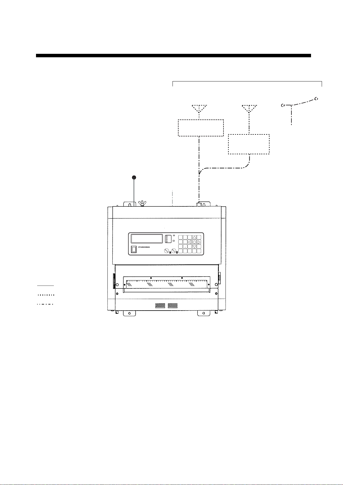
SYSTEM CONFIGURATION........................................................................................viii
1. OPERATION.............................................................................................................1
1.1 Control Description.................................................................................................................1
1.2 Turning the Power On/Off.......................................................................................................3
1.3 Adjusting LCD Contrast..........................................................................................................3
1.4 Adjusting LCD Brilliance and LED Brightness........................................................................3
1.5 Channel and Frequency Displays...........................................................................................3
1.5.1 Channel setting...........................................................................................................3
1.5.2 Fine adjustment of frequency, selection of desired frequency...................................4
1.6 Automatic Receiving...............................................................................................................4
1.7 Manual Receiving...................................................................................................................5
1.8 Timer Receiving......................................................................................................................6
1.8.1 Registering timer programs ........................................................................................6
1.8.2 Choosing timer programs for timer reception.............................................................7
1.8.3 Disabling timer operation when awaiting reception....................................................7
1.8.4 Unlocking keyboard during timer reception................................................................7
1.8.5 Confirming timer programs.........................................................................................8
1.9 Processing Facsimile Images.................................................................................................9
1.9.1 Speed and IOC ...........................................................................................................9
1.9.2 Manual phasing.........................................................................................................10
1.9.3 Synchronization ........................................................................................................10
1.9.4 Reverse mode...........................................................................................................10
1.10 Sleep Timer...........................................................................................................................11
10.1.1 Activating the sleep timer..........................................................................................11
10.1.2 Unlocking keyboard during sleep timer ....................................................................11
10.1.3 Disabling the sleep timer ..........................................................................................11
1.11 Setting the Date and Time....................................................................................................12
1.12 Adding Facsimile Channels..................................................................................................13
1.13 ISB Function .........................................................................................................................14
1.13.1 Enabling, disabling ISB function...............................................................................14
1.13.2 Setting ISB shift width...............................................................................................14
1.14Operation with an External Receiver....................................................................................15
1.14.1 Enabling, disabling external receiver use.................................................................15
1.14.2 Operation ..................................................................................................................15
2. MAINTENANCE .....................................................................................................17
2.1 Backup Battery .....................................................................................................................17
2.2 Lubrication and Cleaning......................................................................................................17
2.3 Replacement of Fuse............................................................................................................18
2.4 Replacement of Recording Paper........................................................................................18
2.5 Clearing the RAM .................................................................................................................21

v
3. INSTALLATION ......................................................................................................23
3.1 Main Unit.............................................................................................................................. 23
3.2 Antenna................................................................................................................................ 24
3.2.1 General antenna connection.................................................................................... 24
3.2.2 Whip or wire antenna............................................................................................... 25
3.2.3 Installation of optional preamp unit (FAX-5) ............................................................ 25
3.3 Wiring................................................................................................................................... 26
3.3.1 Power connection .................................................................................................... 26
3.3.2 Ground ..................................................................................................................... 27
3.3.3 External equipment.................................................................................................. 27
3.3.4 Whip or wire antenna............................................................................................... 28
3.3.5 Setting of S1 on RCV board (preamp unit is used) ................................................. 29
FACSIMILE STATION TABLES ....................................................................................31
SPECIFICATIONS.....................................................................................................SP-1
Declaration of conformity
PACKING LISTS ......................................................................................................... A-1
OUTLINE DRAWINGS ................................................................................................ D-1
INTERCONNECTION DIAGRAM................................................................................ S-1

v
i
FOREWORD
A Word to the Owner of the FAX-410
FURUNO Electric Company thanks you for purchasing the FURUNO FAX-410 Facsimile
Receiver. We are confident you will discover why the FURUNO name has become
synonymous with quality and reliability.
Since 1948, FURUNO Electric Company has enjoyed an enviable reputation for quality and
reliability throughout the world. This dedication to excellence is furthered by our extensive
global network of agents and dealers.
Your equipment is designed and constructed to meet the rigorous demands of the marine
environment. However, no machine can perform its intended function unless properly
installed and maintained. Please carefully read and follow the operation, installation and
maintenance procedures set forth in this manual.
We would appreciate feedback from you, the end-user, about whether we are achieving our
purposes.
Thank you for considering and purchasing FURUNO.
Features
The FAX-410 uses an Individual scanning recording thermal head to produce high quality
facsimile images.
•Electronic scanning with thermal head recording system provides clear image, quiet
operation.
•Programmed with all existing facsimile stations and frequencies. User may also program
channels and edit existing channels.
•Fully automatic facsimile operation with built-in schedule timer. Storage for 16 timer
programs.
•Fully automatic selection of speed, IOC, phase alignment and frequency. Manual selection
also available.
•9-tone gradation recording provides clear and detailed weather images from satellites.
•ISB shift function tracks frequency of SSB multiplex broadcasts whose frequencies
typically shift 1-2 kHz.
•Signal from external receiver may also be recorded.
•Automatic start/stop circuit provided in accordance with WMO standard.
Version No.
1.*
** denotes minor modifications.

vii
EQUIPMENT LIST
Standard supply
Name Type Code No. Qty Remarks
Facsimile Receiver FAX-410 - 1
Installation Materials CP08-02001 000-161-812 1 set DC spec. See the
Packing Lists
followed.
CP08-02002 000-161-813 1 set AC spec.
Accessories FP08-00900 000-161-814 1 set
Spare Parts SP08-02201 000-161-815 1 set DC spec.
SP08-02202 000-161-816 1 set AC spec.
Optional supply
Name Type Code No. Remarks
Preamp Unit FAX-5 000-075-016 w/15 m cable
Preamp Unit FAX-5 000-075-049 w/1 m cable
Whip Antenna 04S4176 000-153-122 2.6 m, for use with FAX-5
FAW-6R2 000-572-108 6 m
FAW-6R2A 000-107-921 6 m, w/mounting bracket
Hose Clamp OP08-11 005-946-960 For mounting preamp unit
Matching Box ARD-1 005-502-230
Antenna Cable
Extension Kit OP04-2 *10M* 000-041-174 10 m, 3D-2V, w/MP3 connector at
both ends
OP04-2 *20M* 000-041-175 20 m, 3D-2V, w/MP3 connector at
both ends
OP04-2 *30M* 000-041-176 30 m, 3D-2V, w/MP3 connector at
both ends
OP04-2 *40M* 000-041-177 40 m, 3D-2V, w/MP3 connector at
both ends
OP04-2 *50M* 000-041-178 50 m, 3D-2V, w/MP3 connector at
both ends
Coaxial Plug FM-MP-7 000-108-859
Adapter MP-M3A 000-108-860
MP-M5A 000-108-861

viii
SYSTEM CONFIGURATION
WHIP ANTENNA
(2.6 m)
PREAMP UNIT
FAX-5
WIRE ANTENNA
: Standard supply
: Optional suppply
: Local supply
BK
FACSIMILE RECEIVER FAX-410
PRG FRQ 123
DIM CH 456
SPD REV 789
IOC RCD C 0 E
TUNE
TIMER
RCD
VOLUME SYNC
POWER
ON
OFF
FACSIMILE RECEIVER FAX-410
OR
MATCHING BOX
ARD-1
Choose one
WHIP ANTENNA
(6 m)
FACSIMILE RECEIVER
FAX-410
12-24 VDC
OR
100/115/200/230 VAC

1
1. OPERATION
1.1 Control Description
Paper feed
control
Paper release lever
Upward position: Release
Downward position: Lock
PRG FRQ 123
DIM CH 456
SPD REV 789
IOC RCD C 0 E
TUNE
TIMER
RCD
VOLUME SYNC
POWER
ON
OFF
FACSIMILE RECEIVER FAX-410
Paper compartment
lid
Control panel
Paper cutter
FACSIMILE RECEIVER FAX-410
PRG FRQ 123
DIM CH 456
SPD REV 789
IOC RCD C 0 E
TUNE
TIMER
RCD
VOLUME SYNC
POWER
ON
OFF
FACSIMILE RECEIVER FAX-410
Control description
Control,
indicator Description
POWER
ON
OFF
Turns power on and off.
VOLUME
Adjusts volume of receive signal and key beep.
SYNC
Fine tunes the phasing signal.

1. OPERATION
2
Control description (con’t from previous page)
Control,
indicator Description
PRG
• Enables a setting mode (in combination with numeric key). Press the key
followed by appropriate numeric key to choose setting mode.
1- Choose internal or external receiver.
2- Set timer reception functions.
3- Set sleep timer.
4-Add or edit channels.
5- Set date and time.
6- Set ISB shift.
7-Adjust LCD contrast.
9- Clear RAM.
• Returns to top page in setting mode.
FRQ
• Changes from channel mode to frequency mode.
• Sets frequency in frequency mode.
DIM
Adjusts LCD brilliance and LED brightness, in five levels.
CH
• Changes from frequency mode to channel mode.
• Sets channel in channel mode.
SPD
Chooses recording speed.
REV
• Reverses recording format of image currently being received.
• Inserts decimal point when entering frequency, asterisk when entering channel.
• Chooses + or -
IOC
Chooses IOC (Index of Cooperation).
RCD
Starts and stops recording.
E
Confirms setting.
C
• Clears data in setting mode.
• Switches from setting mode to standby mode.
2
Raises channel in channel mode, or raise frequency in frequency mode.
4
Manual phasing (leftward) in recording. Each press shifts the recording leftward by
6.4 mm.
5
Displays date and time.
6
Manual phasing (rightward) in recording. Each press shifts the recording rightward
by 6.4 mm.
8
Lowers channel in channel mode, or lowers frequency in frequency mode.
TUNE
The top, middle or bottom LED lights when the receive frequency is higher, the
same or lower than programmed frequency, respectively.
TIMER
Lights when the timer mode or sleep mode is active.
RCD
• Lights when recording is in progress.
• Flashes when receiving start signal.

1. OPERATION
3
1.2 Turning the Power On/Off
Press the POWER key to turn the power on or off. When the power is applied, the last-used
channel appears.
1.3 Adjusting LCD Contrast
1. Press the PRG key.
2. Press the 7key to show the contrast setting screen.
SET CONTRAST
by S/TKEY
3. Press ▲or ▼key to adjust the contrast, in ten (0-9) levels. The chosen level appears
on the LCD.
4. Press the Ekey.
5. Press the Ckey to return to the standby display.
1.4 Adjusting LCD Brilliance and LED Brightness
Use the DIM key to adjust LCD brilliance and LED brightness, in five levels.
1.5 Channel and Frequency Displays
The channel display may be chosen with the CH key; the frequency display with the FRQ
key.
The channel number is displayed in three figures. The left-two digits are the station number
and the last digit is the frequency code. In the example below the channel number is 000.
C000 JMH 3622.5
S120 I576
CH No. Call Sign Frequency CH No. Call Sign Frequency
Speed IOC Speed IOC
000 JMH F 3622.5
S120 I576
"F" denotes frequency
display mode.
"C" denotes channel
display mode.
Channel display Frequency display
1.5.1 Channel setting
In the channel display mode, press ▲or ▼key to choose channel number. A channel may
also be selected manually by pressing the CH key in the channel display mode and then
entering channel number (3 digits) with the numeric keys. An asterisk (*) may be entered at
the 3rd digit location (with REV key) to receive the most sensitive frequency of a channel
group automatically.

1. OPERATION
4
1.5.2 Fine adjustment of frequency, selection of desired frequency
In the frequency display mode, use the ▲or ▼key to fine tune a frequency, in resolution of
0.1 kHz. When properly tuned, the center TUNE LED (green) lights. If the upper TUNE LED
(red) is lit, use the ▲key, and if the lower TUNE LED (red) is lit, use the ▼key.
Frequency may also be entered manually by pressing the FRQ key in the frequency display
mode, and then entering frequency (4-5 digits) by using the numeric keys and the REV key
(for entering decimal point). The available frequency range is 2000.0 – 24999.9 kHz.
1.6 Automatic Receiving
Once you choose the facsimile station from which to receive, the system goes into standby
to await the start signal from the facsimile station. Recording starts when the start signal is
received.
1. If the frequency display mode is active, press the CH key to show the channel display.
C00* JMH 3622.5
S120 I576 * Asterisk indicates automatic
frequency selection.
2. Press the ▲or ▼key to choose channel desired.
Note: Alternatively, you may enter the frequency of the broadcasting station by pressing
the FRQ key and entering frequency with the numeric keys and the REV/zkey (for
decimal point).
When the start signal is received, the message "AUTO START SEARCHING FRAME"
appears and the RCD LED (orange) flashes. Speed and IOC are automatically adjusted
when recording starts. The RCD LED lights during recording.
Note: The TUNE LED goes off when the RX level goes below a certain level or the
equipment is not receiving. Even if the TUNE LED goes off, the equipment records the fax
signal as long as the S/N ratio is suitable. Therefore, this is not a sign of TUNE LED trouble
or equipment malfunction.
Stopping recording
Recording stops automatically when the stop signal is received. You may also stop the
recording manually by pressing the RCD key. The RCD LED goes off when recording is
stopped.

1. OPERATION
5
1.7 Manual Receiving
This section shows you to manually receive a facsimile broadcast. For example, you may
want to receive a facsimile broadcast already in progress or receive from a facsimile station
that does not use start and stop signals.
1. If the frequency display mode is active, press the CH key to show the channel display.
C000 JMH 3622.5
S120 I576
2. Press the ▲or ▼key to choose channel desired.
Note: Alternatively, you may enter the frequency of the broadcasting station by pressing
the FRQ key and entering frequency with the numeric keys and the REV/zkey (for
decimal point).
3. Press the RCD key.
MANUAL START SEARCHING FRAME appears on the display and RCD LED (orange)
flashes.
4. If recording does not start after a while, press the RCD key again. The RCD LED stops
flashing and lights.
5. If necessary, use the SPD and IOC keys to choose rotation speed and IOC, respectively,
referring to paragraph 1.9.1.
Stopping recording
Recording is automatically stopped when the stop signal is received. To stop recording
manually, press the RCD key. The RCD LED goes off when recording is stopped.

1. OPERATION
6
1.8 Timer Receiving
Most facsimile stations transmit facsimile images in accordance with a schedule issued by
relative meteorological observatory. (You can find facsimile schedules in the publication
“Meteorological Facsimile Broadcasts,” available through meteorological observatory
bodies.) If you wish to receive a certain facsimile broadcast on a regular basis, therefore,
the timer mode will virtually allow you “hands-off” automatic operation. 16 timer programs
may be set.
1.8.1 Registering timer programs
1. Press the PRG key.
C000 JMH 3622.5
S120 I576
Standby display
SET PRG. No. 1-9
ESC PUSH C KEY
Setting mode
[PRG] key
[C] key
2. Press the 2key to show the timer reception setting mode.
TIMER RCV : 1-OFF
2-ON 3-RCL 4-STR
3. Press the 4key to choose STR (Store).
STORE TIMER REG
SET REG No. 0-F
4. Use the ▲or ▼key to choose timer program number and press the Ekey. For example,
choose “1” and the display then looks something like the one below.
R1 SET CHANNEL
No. in 3 FIGURES
5. Enter channel number and press the Ekey. For automatic selection of frequency, press
REV after entering third digit.
R1 C000 SET DAY
of THE WEEK by ST
6. Set the day of the week which to receive the program, using the ▲or ▼key. Choose
the asterisk (*) to get a broadcast daily at the same time.
7. Press the Ekey.
R1 C000 MON
SET START/STOP
8. Set start and end times, in 24-hour notation, using the numeric keys. (When registering
programs which follow one another consecutively, the time between programs should be
set at least one minute apart. For example, you have two programs to register, the first
at 12:00-12:30 and the second at 12:30-13:00. In this case set the time for the second
program to 12:31-13:00.)
9. Press the Ekey.
10.Press the Ckey to return to the standby display.

1. OPERATION
7
1.8.2 Choosing timer programs for timer reception
Choose timer programs for timer reception as follows:
1. Press the PRG key and the 2key to show the timer reception setting mode.
TIMER RCV : 1-OFF
2-ON 3-RCL 4-STR
2. Press the 2key to choose ON.
SET REG No. 0-F
PUSH S/T&X& E KEY
3. Use the ▲or ▼key to choose timer program number and press the ►key.
TIMER RCV No.: 4
0123
4. Repeat step 3 as necessary to choose other programs.
5. After choosing all programs necessary, press the Ekey.
The start and stop times of the earliest program are displayed. The TIMER LED (orange)
lights when timer recording is enabled. Note that all keys except the PRG key are locked.
1.8.3 Disabling timer operation when awaiting reception
To cancel a timer program awaiting reception (next program’s start and stop times appear
on the display), do the following:
1. Press the PRG key and the message shown below appears.
TIMER RCV : OFF?
PUSH E KEY
2. Press the Ekey.
1.8.4 Unlocking keyboard during timer reception
All keys except the PRG key are locked during recording to prevent accidental adjustment
of the equipment. If you need to operate the keyboard when timer reception is active, do the
following:
1. Press the PRG key, and the following screen appears.
KEY LOCK : OFF?
PUSH E KEY
2. Press the Ekey to unlock the keyboard.

1. OPERATION
8
1.8.5 Confirming timer programs
Do the following to confirm timer programs which you have entered.
1. Press the PRG key and the 2key to show the timer reception setting mode.
2. Press the 3key to choose RCL (Recall).
RECALL TIMER REG
SET REG No. 0-F
3. Use the ▲or ▼key to choose timer program number, and the contents of the timer
program selected are displayed.
4. Press the Ckey several times to return to the standby display.

1. OPERATION
9
1.9 Processing Facsimile Images
Speed, IOC, phasing, synchronization and image format may be adjusted during recording.
1.9.1 Speed and IOC
Choose the correct speed and IOC, otherwise the image will be received as shown in the
illustration below.
Wrong Speed or IOC and Image
Wrong speed: "60" chosen instead of "120"
Two images are displayed.
Wrong speed: "120" chosen instead of "60"
Overlapped image appears.
Wrong IOC
The image will be extended (or foreshortened) when "288" (or 576)
is selected for transmission with the IOC of "576 (or 288)."
Speed
Speed is the rotation speed of the drum (on which the original image is fitted) at the
facsimile transmitter: 60, 90 or 120 rpm. To choose speed, do the following:
1. Press the SPD key to show the speed display.
SPEED: 120
1-120 2-90 3-60
2. Press the 1, 2or 3key as appropriate to choose correct speed.

1. OPERATION
10
IOC
IOC is the line density standard assigned by WMO: IOC 576, high density, IOC 288, low
density. To choose IOC, do the following:
1. Press the IOC key to show the IOC display.
IOC: 576
1-576 2-288
2. Press the 1or 2key as appropriate to choose correct IOC.
1.9.2 Manual phasing
When the FAX-410 starts recording a broadcast already in progress, or noise prevents
detection of the phasing signal, a dead sector (black or white stripe) may appear on the
recording. This phenomenon is due to phase mismatching. When this occurs, correct phase
mismatching, after the facsimile has been received.
Dead sector (can be white)
To adjust phasing, use the ◄or ►key. Press ◄to shift leftward; ►to shift rightward. Each
press shifts the recording leftward (rightward) by about 6.4 mm.
1.9.3 Synchronization
If the dead sector is plotted at an angle even when the phase is properly selected, adjust
the synchronization to display the dead sector straightly, using the SYNC control.
(SYNC)
Rotate
clockwise
Rotate
counterclockwise
1.9.4 Reverse mode
Most facsimile stations transmit facsimile images with black text on a white background.
Some stations, however, print reversely of that format. If you want to record a facsimile in a
format different from how it is being received, press the REV key to display the screen
shown below. Then, press the 1key to turn OFF reverse or the 2key to turn ON reverse.
REVERSE: OFF
1-OFF 2-ON
Other manuals for FAX-410
3
Table of contents
Other Furuno Fax Machine manuals

Furuno
Furuno FAX-30 User manual

Furuno
Furuno FAX-408 User manual

Furuno
Furuno FAX-30 Manual

Furuno
Furuno FAX-30 User manual

Furuno
Furuno PFX-50 User manual

Furuno
Furuno FAX-207 User manual

Furuno
Furuno FAX-207 User manual

Furuno
Furuno FAX-30 User manual

Furuno
Furuno DFAX FAX-208/A/N User manual

Furuno
Furuno FAX-30 User manual