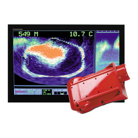
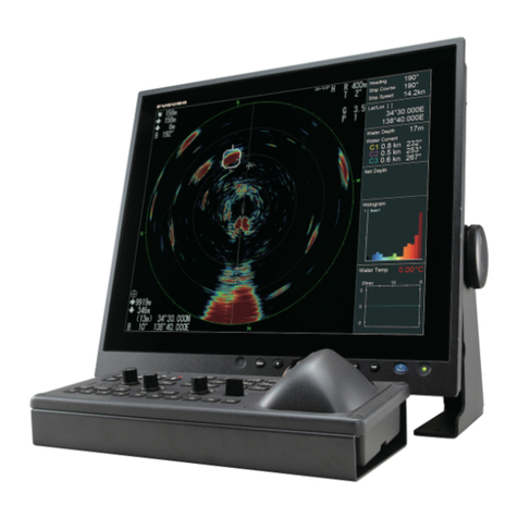
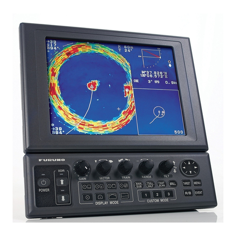
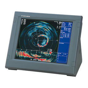
Furuno 3D Sonar Visualizer F3D-S User manual

3D Sonar Visualizer
F3D-S
OPERATOR'S MANUAL
www.furuno.com
Model
(Option for FSV-25/FSV-25S)


i
TABLE OF CONTENTS
FOREWORD.................................................................................................................... ii
SYSTEM CONFIGURATION .......................................................................................... iii
1. OPERATIONAL OVERVIEW.................................................................................... 1
1.1 How to Start and Quit the Software...............................................................................1
1.2 Display Screen Overview ..............................................................................................2
1.2.1 3D-View mode........................................................................................................3
1.2.2 Top-View mode......................................................................................................3
1.2.3 Side-View mode.....................................................................................................4
1.2.4 Vslice-View mode...................................................................................................4
1.2.5 Other indication......................................................................................................5
1.3 Operational Overview .................................................................................................... 5
1.4 How to Change the Viewpoint .......................................................................................5
1.5 How to Set the Sonar ....................................................................................................6
1.6 How to Set the Vslice Bearing Mark..............................................................................6
1.7 How to Set the Depth Range Line.................................................................................7
1.8 How to Measure the Range by Range Cursor...............................................................7
2. UPPER USER MENU ............................................................................................... 8
2.1 How to Reset the Viewpoint ..........................................................................................8
2.2 How to Scale or Move the View.....................................................................................9
2.3 How to Enter the Echo Region Mark .............................................................................9
2.4 How to Enter the Event Mark.......................................................................................10
2.5 How to Enter the Purse Net Mark................................................................................11
2.6 How to Enter the Trawl Mark.......................................................................................12
2.7 Seabed Color...............................................................................................................15
2.8 User Program ..............................................................................................................17
3. LOWER USER MENU ............................................................................................ 18
3.1 How to Save the View Setting .....................................................................................18
3.2 How to Connect/Disconnect the PC to the FSV-25.....................................................19
3.3 How to Start and Stop Data Recording .......................................................................20
3.4 How to Replay the Echo Data .....................................................................................20
3.5 Advanced Setting ........................................................................................................21
4. TROUBLESHOOTING............................................................................................ 23
APPENDIX 1 ERROR MESSAGES .........................................................................AP-1

ii
FOREWORD
Congratulations on your choice of the FURUNO 3D Sonar Visualizer F3D-S. We are confident you
will see why the FURUNO name has become synonymous with quality and reliability.
Since 1948, FURUNO Electric Company has enjoyed an enviable reputation for innovative and
dependable marine electronics equipment. This dedication to excellence is furthered by our ex-
tensive global network of agents and dealers.
Please carefully read and follow the recommended procedures for operation and maintenance.
Features
This software, installed in a PC, displays the 3D echo data obtained from the FURUNO model col-
or scanning sonar FSV-25/FSV-25S. Hereafter, FSV-25 refers to FSV-25 or FSV-25S.
The main features of the F3D-S are as shown below.
• Fish schools of surface to middle layer can be observed at the same time.
• Movement of fish schools can be viewed instantly.
• 3D visualization of ship’s surroundings.
• Storage and replay of picture and settings.
• Four views (3D-View, Top-View, Side-View, and Vslice-View) can be displayed on the screen.
• Relative position of fish schools, trawl doors, and net can be easily understood.
• InstantAccess bar™for direct access to menus.
• Various marks (echo region mark, event mark, purse net mark, trawl mark, etc.) can be entered.
Program version no.
1050955-01.**
** denotes minor modifications.
Software used in this product
This product includes software to be licensed under the MIT. Please refer to the “OSS” directly in
the supplied CD-ROM about the agreement of this software.

iii
SYSTEM CONFIGURATION
PC
(Local supply, program
installed in PC)
LAN cable
Color Scanning Sonar FSV-25/FSV-25S
Processor Unit
FSV-2503/2503S
IF Unit
FSV-8502
Control Unit FSV-2501
Hull Unit
FSV-253/254
Transceiver Unit
FSV-251
Junction Box
FSV-2550
Raise/Lower
Control Box
FSV-2530
Monitor
Power Supply Unit
FSV-252
100/110/115/220/230 VAC,
1ø, 50/60 Hz
Rectifier
RU-1746B-2
100/110/115/220/230 VAC,
1ø, 50/60 Hz
12-24
VDC
: Standard supply
: Local or optional supply
200-220 VAC,
3ø, 50/60 Hz

1
1. OPERATIONAL OVERVIEW
1.1 How to Start and Quit the Software
1. Turn the FSV-25 on.
2. Turn the PC on and login with administrator rights.
3. Insert the USB dongle into a USB port on the PC. The LED in the dongle lights red. The USB
dongle is required to use this software. Take care not to lose it.
4. Double-click the “3D” shortcut icon on the desktop to start the software.
After the start up is completed, the following screen appears.
Note: If the following message appears, click [OK] to deleted the message and then re-insert
the USB dongle.
5. To quit the software, click the close button (x) at the upper right-hand corner of the screen. All
setting information is saved to the folder “C: \ Users \ User name \ Documents \ FURUNO \
F3D-S”.
Note: If the information has not been saved, open the properties of the above-mentioned files
and check that they are not “read only”.
3
12
1: Minimize the
window.
2: Maximize the
window.
(Operation is
not available.)
3: Close the
window.
xx xx

1. OPERATIONAL OVERVIEW
2
1.2 Display Screen Overview
When the sonar is available and the F3D-S software is started, a screen, similar to that shown
below, appears. There are four view modes; 3D-View, Top-View, Side-View, and Vslice -View.
No. Name Description
1Upper InstantAccess bar™• Click to show the upper user menu.
• Click to hide the upper user menu.
2 “Side-View” echo • Shows a horizontal view from stern side. This is the de-
fault setting.
• When [Rotate Top-View/Side-View] is turned on, shows
a horizontal view from foreside of the screen. (See
section 3.5.)
3 “Top-View” echo Shows a “bird’s-eye-view” of the echoes around the ship.
4 “3D-View” echo Shows a diagonal 3D view of the echoes.
5 “Vslice-View” echo Shows vertical "slices" of echoes at the same orientation as
the vertical settings on the FSV-25.
6 Settings of sonar Shows the range, gain and user program number.
7 External input data Shows the data output from external equipment connected
to the FSV-25.
8 Echo volume Shows the volume calculated from the echo region mark
function.
9Lower InstantAccess bar™• Click to show the lower user menu.
• Click to hide the lower user menu.
-10.0°C
0.4kn 237°
0.4kn 255°
P 1
11
55
33
2244
99
66
77
88
33°50.245N
119°44.237W
xx xx

1. OPERATIONAL OVERVIEW
3
1.2.1 3D-View mode
The 3D-View mode shows a diagonal 3D view of the echoes. You can change the viewpoint. For
details, see section 1.4. The 3D-View mode is useful for viewing the entire three-dimensional area
around own ship.
1.2.2 Top-View mode
The Top-View mode shows a “bird’s-eye-view” of the echoes around the ship. The Top-View
mode is useful for measuring the horizontal distance and direction to the fish school.
Vslice number
Vslice bearing
mark
Bearing scale
Vslice bearing
plane
(Translucent
white fan)
Range ring
(Translucent
green dotted
line)
Depth line
(Translucent
yellow dotted
line)
Heading line
Own ship mark
Track
(Translucent
green line)
North mark
(Translucent
white short
line)
Vslice number
Vslice bearing mark
Bearing scale
Range ring
Heading line
North mark Own ship mark
Track

1. OPERATIONAL OVERVIEW
4
1.2.3 Side-View mode
The Side-View mode shows a horizontal view from stern side. This is the default setting. When
[Rotate Top-View/Side-View] is turned on, the Side-View mode shows a horizontal view from fore-
side of the screen. (See section 3.5.) The Side-View mode is useful for measuring the depth of
the fish school.
1.2.4 Vslice-View mode
The Vslice-View mode shows vertical "slices" of echoes at the same orientation as the vertical set-
tings on the FSV-25. You can display two-directional Vslice views. The Vslice-View mode is useful
for detecting the fish school distribution in a specific direction. Also, this mode is useful for com-
paring the depth of two targets in the different direction.
Depth line
Depth range line
(upper limit)
Own ship mark
Depth range line
(lower limit)
Range scale

1. OPERATIONAL OVERVIEW
5
1.2.5 Other indication
The following data are displayed at the top right of the screen.
• Sonar settings: Shows the range, gain and user program number.
• External data: Shows the data received from external equipment.
• Echo volume: Shows the volume calculated from the echo region mark function.
1.3 Operational Overview
1. Click or on the upper or lower InstantAcces bar™to open the user menu.
2. Click an icon to execute the menu function. The selected icon is displayed in cyan. The icons
that have a at the bottom right have additional menus.
3. To deactivate a function, click the icon again. The color for the icon changes from cyan to gray.
4. To hide the user menu, click or on the upper or lower InstantAcces bar™.
1.4 How to Change the Viewpoint
You can change the viewpoint when no menu icons are selected.
To change the viewing angle, drag the 3D-View echo up or down.
To change the view-point origin, drag the 3D-View, Top-View* or Side-View* echo to the right
or left.
*: This function is available on the Top-View and Side-View when checking the box for [Rotate
Top-View/Side-View] in the Advanced Setting menu.
P 3
VOL-1
VOL-2
9999.99
9999.99
-10.0°C
0.4kn 237°
0.4kn 255°
Sonar settings External data
Echo volume
- R: Range (100 m to
5000m)
- G: Gain (0.0 to 10.0)
- P: User program
number (1 to 10)
- HDG: Heading
- COG: Course over ground
- SPD: Speed
- Latitude
- Longitude
- DPTH: Depth
- C1 to C5: Current
- TEMP: Temperature
- VOL-1: Echo volume for echo
region mark 1
- VOL-2: Echo volume for echo
region mark 2
See section 1.5 to
change the setting
value for R, G or P.
33°50.245N
119°44.237W

1. OPERATIONAL OVERVIEW
6
1.5 How to Set the Sonar
The range, gain and user program number are displayed on the top right of the screen.
To change the value, put the cursor on the [R], [G] or [P] area then spin the scrollwheel.
• [R]: Shows the display range (setting range: 100 m to 5,000 m). When the FSV-25 operates in
the H(orizontal)/V(ertical) alternate mode, the setting value is limited to the range of the FSV-
25 in the V(ertical) mode or less.
Note: When the FSV-25 is in the H mode or the H2 (horizontal combination) mode, the TX
(transmission) interval of the FSV-25 is reduced depending on the range setting of the F3D-S.
The TX interval does not decrease when V mode is in use.
• [G]: Shows the receiver gain (setting range: 0.0 to 10.0).
• [P]: Shows the user program number (setting range: 1 to 10). When the cursor is in the [P] area,
the comment* for the selected user program number is displayed on the left.
*: You can set the comment about the menu settings for views including the view arrangement.
For details, see section 2.8.
1.6 How to Set the Vslice Bearing Mark
To set the Vslice bearing mark on 3D-View or Top-View, click the Vslice number and then spin the
scrollwheel, or drag the Vslice number. You can set the Vslice bearing mark while the Vslice num-
ber is displayed in cyan color.
R 700m
G 2.2
P 3
Range
Gain
User program number
Vslice number
Vslice bearing mark
3D-View Top-View
Vslice bearing mark Vslice number
Vslice bearing plane (Translucent white fan)

1. OPERATIONAL OVERVIEW
7
1.7 How to Set the Depth Range Line
To set the depth range line on Side-View, click the depth range line for upper or lower limit and
then spin the scrollwheel, or drag the depth range line. You can set the depth range line while the
depth range line is displayed in cyan color.
1.8 How to Measure the Range by Range Cursor
There are two types of range cursor; circle cursor for the horizontal measurement and parallel cur-
sor for the vertical measurement.
Click the scrollwheel on an area other than the menu icons and move the cursor on a view. Spin
the scrollwheel to measure the range.
To cancel measuring, do one of the followings.
• Click the scrollwheel on an area other than the menu icons.
• When the Vslice number is displayed in cyan, click the Vslice number.
• When the depth range line is displayed in cyan, click the depth range line.
• When the seabed border line is displayed in cyan, click the seabed border line.
Side-View
Depth range line
(upper limit)
Depth range line
(lower limit)
Side-View
Circle cursor
(white dotted line)
Vslice-View
3D-View
Top-View
Parallel cursor
(white dotted
line)
Range
Range
(diameter of a circle)

8
2. UPPER USER MENU
The upper InstantAccess bar™is on the top left side of the screen. Click to show the upper
user menu. Click to hide the upper user menu.
Upper user menus
The upper user menus, except for user program, are displayed by right-clicking on each view.
Click an icon to execute the function. When the upper InstantAccess bar™on the top left side of
the screen is closed, the menu bar on the view disappears and the selected icon is displayed in
cyan on the top left side of the screen. When the upper InstantAccess bar™is open, the menu bar
on the view disappears and the selected icon turns cyan on the upper InstantAccess bar™.
The icons which are unavailable on a view are grayed out and not selectable.
To delete the menu bar on a view, click the area out of a view.
2.1 How to Reset the Viewpoint
Click to reset the viewpoint. The depression and azimuth of the viewpoint are reset to the
setting for the currently selected user program.
Icon Name Description Section
Show Shows the upper user menu. 1.3
Hide Hides the upper user menu. 1.3
Reset Viewpoint Resets viewpoint orientation. This mark is always dis-
played.
2.1
Move/Zoom • Moves view by dragging.
• Adjusts the zoom by spinning the scrollwheel.
2.2
Echo Region Mark 1 Enters the echo region mark 1. 2.3
Echo Region Mark 2 Enters the echo region mark 2. 2.3
Event Mark Enters an event mark on Top-View. 2.4
Purse Net Mark Enters the purse net mark on 3D-View or Top-View. 2.5
Trawl Mark • Enter the trawl mark on 3D-View or Top-View.
• Sets the depth for the trawl mark on Side-View or
Vslice-View.
2.6
Seabed Color Displays seabed in specified color. 2.7
User Program Opens the user program menu. 2.8

2. UPPER USER MENU
9
2.2 How to Scale or Move the View
1. Click to show the upper user menu.
2. Click .
3. To scale the view, put the cursor on a view and spin the scrollwheel.
To move the view, put the cursor on a view and drag the view.
4. Click to deactivate the function.
5. Click to hide the upper user menu.
Note: When you click , the position and size for each view is reset to the setting for the cur-
rently selected user program.
2.3 How to Enter the Echo Region Mark
You can enter the echo region mark on 3D-View, Top-View, or Side-View.
1. Click to show the upper user menu.
2. Click or .
3. Click the point on the echo that is strongly displayed in 3D-View, Top-View, or Side-View. The
echo area, including the point clicked, is displayed in yellow or cyan lines.
The volume for echo region mark is displayed at the right of the screen.
Note 1: You cannot mark an area designated as echo region 2 with echo region mark 1, and
vice versa.
Note 2: When updating the echo display while echo region marks are displayed,
• if there are strong echo after updating near the position of the mark before updating, the
echo region mark is displayed at the area of this echo.
• if there is no corresponding echo, the echo region mark is not displayed.
4. Click or to deactivate the function.
5. Click to hide the upper user menu.
Echo region mark 1 is
displayed in yellow lines.
Echo region mark 2 is
displayed in cyan lines.
Volume for echo region mark 1
Volume for echo region mark 2 (Unit: 1,000,000 m3)

2. UPPER USER MENU
10
How to delete the echo region mark
To delete the echo region mark and the volume, do one of the following:
• Click or , and then click .
• Click the echo region mark on the view.
2.4 How to Enter the Event Mark
You can enter the event mark on Top-View.
1. Click to show the upper user menu.
2. Click .
3. Click the point on Top-View to enter the event mark.
Latest event mark
4. Repeat step 3 to enter other event marks. The event marks are numbered as follows.
Note 1: Up to 10 event marks can be entered. When entering the 11th event mark, the oldest
event mark is deleted and the 11th input event mark is displayed as the latest event mark.
Note 2: When updating the echo display, the event mark out of the view is not displayed.
5. Click to deactivate the function.
6. Click to hide the upper user menu.
How to delete the event mark
To delete the event mark, do one of the followings.
• Click and then click to delete the oldest event mark.
• Right-click the event mark on Top-View to display the [Delete] menu and then click [Delete].
First input
event mark
12 3
Second input
event mark
Third input
event mark
Latest input
event mark
New Old

2. UPPER USER MENU
11
2.5 How to Enter the Purse Net Mark
You can enter the purse net mark on 3D-View or Top-View.
1. Click to show the upper user menu.
2. Click .
3. Click the position on 3D-View or Top-View to enter the purse net mark in cyan color. When
moving the cursor to an area other than the purse net mark, the purse net mark color changes
to white.
Note: When updating the echo display, the purse net mark outside the on-screen field of view
are not displayed.
4. Click to deactivate the function.
5. Click to hide the upper user menu.
How to move the purse net mark
To move the purse net mark, do one of the following:
• When is selected, put the cursor on the purse net mark and drag the purse net mark to the
desired position.
• When is not selected, right-click the purse net mark then click [Move]. The icon chang-
es to the selected status. Drag the purse net mark to the desired position.
How to delete the purse net mark
To delete the purse net mark, do one of the following:
• When is selected, click .
• When is not selected, right-click the purse net mark then click [Delete].
3D-View Top-View

2. UPPER USER MENU
12
2.6 How to Enter the Trawl Mark
You can enter the trawl mark on 3D-View or Top-View.
1. Click to show the upper user menu.
2. Do the following steps on 3D-View referring to the figures.
• 3D-View: The direct distances from own ship to the center of each trawl door are displayed
in numerical values.
Click and then move the cursor to the
view area.
12Click the position to place the trawl door
marks.
3Click another position to move one of two
trawl door marks.
4Move the cursor to the area other than
the trawl door marks.
Trawl door marks
Trawl mouth mark
Warps
Reins
Distance from own ship to the
center of trawl door mark
To reset the trawl mark, right-click a trawl door mark and click [Reset]. You can start
from step 1 .

2. UPPER USER MENU
13
• Top-View: The horizontal distances from own ship to the center of each trawl door are dis-
played in numerical values. Also, the distance between two trawl doors is displayed in nu-
merical value.
• Side-View: The depth for the center of trawl door is displayed in numerical value (default: 0
m).
• Vslice-View: The depth for the center of trawl door is displayed in cyan color, or white dotted
line. When the cursor is on this line or a trawl mark, this line is displayed in cyan color. On
other occasions, this line is displayed in white.
3. To set the trawl mark depth on Side-View or Vslice-View, do one of the following:
4. Click to deactivate the function. All numerical indications related to the trawl mark are
removed.
5. Click to hide the upper user menu.
On Side-View
• Put the cursor on a trawl door mark and drag the trawl door mark up or down.
• Click the location you want to set as the depth.
On Vslice-View
• Put the cursor on the dotted line. The line color changes from white to cyan color. Drag this
line up or down.
• Click the location you want to set as the depth.

2. UPPER USER MENU
14
How to change the horizontal position for trawl mark
To change the horizontal position for trawl mark, do one of the following:
• When is selected, put the cursor on a trawl door mark and drag the trawl door mark to the
desired position.
• When is not selected, right-click a trawl door mark then click [Move]. The icon changes
to the selected status. Drag the trawl door mark to the desired position.
How to delete the trawl mark
To delete the trawl mark, do one of the following:
• When is selected, click .
• When is not selected, right-click a trawl door mark then click [Delete].
Trawl filter
The trawl filter function detects the trawl doors. The echoes from trawl doors are emphasized and
the echoes from fish school and seabed are suppressed.
Note: The trawl filter can selectively detect the trawl doors in the specified direction. However, in
some cases, where the trawl doors are at the edge of the detection area, the trawl doors may not
appear on-screen. If this happens, disable the trawl filter.
To activate the trawl filter, do the following.
1. Click to show the upper user menu.
2. Click .
3. Click to activate the trawl filter function. The icon is highlighted.
To deactivate the trawl filter, click again.
Trawl filter: OFF
Trawl mark: ON
Trawl filter: ON
Trawl mark: ON
Central orientation of trawl filter
(The orientation from own ship to the midpoint of the line
connecting one trawl door mark to the other trawl door mark)
Trawl filter: ON
Trawl mark: OFF
: Central orientation
of trawl filter
(Requires Top
View or 3D View)
Click any location
on the screen.
The moves to
the same distance
from the own ship
mark along the
track line.

2. UPPER USER MENU
15
2.7 Seabed Color
The seabed can be displayed in a specified color. You can set the seabed border line on Vslice-
View.
1. Click to show the upper user menu.
2. Click to display the seabed border line on Vslice-View.
3. Move the cursor on the seabed border line. The line color changes from translucent yellow to
cyan.
4. To set the depth for the seabed border line, drag seabed depth mark 1 up and down. To set
the tilt for the seabed border line, drag seabed depth mark 2 up and down.
To deactivate seabed color function, click .
Seabed Color: OFF Seabed Color: ON
Seabed border line
Seabed depth mark 2
Seabed depth mark 1
Other manuals for 3D Sonar Visualizer F3D-S
1
Table of contents
Other Furuno Sonar manuals

Furuno
Furuno DS-30 Manual

Furuno
Furuno CSH-8L User manual

Furuno
Furuno TS-331A User manual

Furuno
Furuno DS-30 User manual

Furuno
Furuno FCV-552 Operators User manual

Furuno
Furuno CH-270 User manual

Furuno
Furuno CI-88 User manual

Furuno
Furuno CSH-5 MARK-2 User manual

Furuno
Furuno CSH-21 User manual

Furuno
Furuno FCV-381 User manual

Furuno
Furuno FSV-75 User manual

Furuno
Furuno DS-60 User manual

Furuno
Furuno FCV-1000 User manual

Furuno
Furuno DS-30 User manual

Furuno
Furuno CH-250 User manual

Furuno
Furuno FSV-35 User manual

Furuno
Furuno CH-500 User manual

Furuno
Furuno CSH-8LMARK-2 User manual

Furuno
Furuno CSH-5 User manual

Furuno
Furuno MODEL CSH-73 User manual