Operation Normal/High Speed Mode Select
The operation mode is set on "Normal mode" from the factory. To
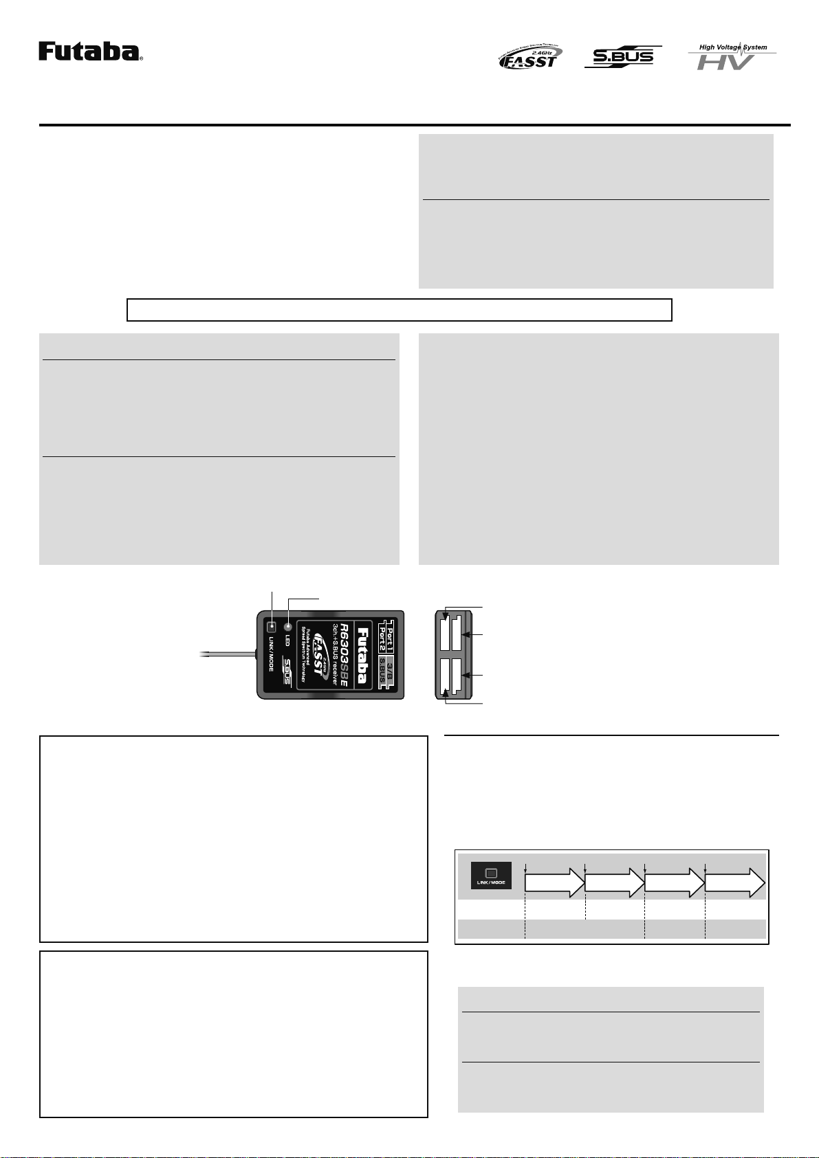
change the mode please follow the steps below.
14URNOFFTHERECEIVER
20RESSANDHOLDTHELink/ModeBUTTONANDTURNONTHERECEIVER
0RESSANDHOLDTHEBUTTONFORMORETHENSECOND4HE ,%$
WILLSTARTTOmASHANDWILLINDICATETHECURRENTSTATUS
32ELEASETHEBUTTON
44URNOFFTHERECEIVER
By following these steps the receiver modes can be switched back and
forth between normal and high speed modes.
0 to 1 sec. More than 1 sec.
0 sec. 1 sec.
Press and Hold
Turn on the receiver.
No function
Showing the CURRENT
mode with blink.
Red Blink = Normal
Green/Red Blink =
High Speed
Solid as the mode changed.
Red Solid = Normal
Green/Red Solid = High
Speed
(Become Red after 1 second)
㸦Function㸧To change the mode between
Normal and High Speed
㸦LED
Status㸧
Please check the operation mode by observing the LED when turning on
WKHUHFHLYHU7KHEHVWZD\WRFRQ¿UPWKHPRGH\RXDUHRQLVWRPDNHVXUH
that there are no other
FASST
transmitters turned on around you.
When turning on the receiver, the LED will be;
s2EDWHENON.ORMALMODE
s'REENAND2EDMAKINGORANGE WHENON(IGH3PEEDMODE !FTER
SECONDSTHE,%$WILLCHANGETORED
If there are any FASST transmitters turned on around the receiver, the
LED may show the above status, but just for a brief moment and then
change to the status indicated in the "LED indication" table below.
FUTABA CORPORATION
1080 Yabutsuka, Chosei-mura, Chosei-gun, Chiba-ken, 299-4395, Japan
Phone: +81 475 32 6982, Facsimile: +81 475 32 6983
)87$%$&25325$7,21
LED Indication
'REEN 2ED 3TATUS
Solid Solid )NITIALIZINGWHENON(IGH3PEEDMODE
Off Solid No signal reception
Solid Off 2ECEIVINGSIGNALS
Blink Off 2ECEIVINGSIGNALSBUT)$ISUNMATCHED
Alternate blink 5NRECOVERABLEERROR%%02/-ETC
CH group table
#H groUpL%D BlinK0ort 0ort
groUp 2ed 1time #H#H
groUp 2ed 2time #H#H4
groUp 2ed 3time #H#H4
groUp 4 'reen 1time #H#H
groUp 'reen time #H#H7
groUp 'reen time #H4 #H8
groUp 7 2ed'reen 1time #H #H
groUp 8 2ed'reen time not Used not Used
groUp 9 2ed'reen time not Used not Used
※)nitial setting is groUp .
※The groUps 8 and 9 are not UsUally Used.
※#H port and S."5S port never change.
R6303SBE
[Example:ConnectingGYA431toGroup3]
CH4
Rudderservo
CH6
2ndAileronservo
CH2
Elevatorservo
Port1
Port2
S.BUS
3/B CH1
Aileronservo
Battery CH3
Throttleservo
(GYA431isusedfortheaileronofanairplane)
GYA431
HUB
When using the R6303SBE Receiver with
the GYA430, 431 and CGY750
The following table corresponds to the gyro's functions. A port can be
used effectively. The servo which a gyro controls is connected to a gyro.
* 0lease refer to the description of each gyro manUal.
S.BUS gyro group table
'yro control #H#H groUp
2Udder groUp
%levator groUp
!ileron groUp
%levator+2Udder groUp 4
!ileron+2Udder groUp
!ileron+%levator groUp
!ileron+%levator+2Udder
or #'97 groUp 7
When S.BUS is used
* Set the channel of S.BUSSERVOSBYUSINGANSBC-1CHANNELCHANGERCIU-2
53"SERIALINTERFACEORTHEPROGRAMMINGSOFTWAREINTHE18MZ transmitter.
* &DQDOVREHXVHGWRJHWKHUZLWKFRQYHQWLRQDOVHUYRV+RZHYHUFRQYHQWLRQDO
servos cannot be used by the S.BUSRXWSXW
* :KHQXVLQJVHUYRVZLWKDUHPRWHEDWWHU\SDFNXVHS.BUS+XEZLWK&DEOH
ZD\UHPRWHEDWWHU\SDFNXVH
3OHDVHUHIHUWRWKHLQVWUXFWLRQPDQXDORIS.BUS+XEZLWK&DEOHZD\UH-
PRWHEDWWHU\SDFNXVHIRUWKHFRQQHFWLRQPHWKRG
7XUQRQWKHSRZHULQWUDQVPLWWHUĺUHFHLYHURUGHU,QDGGLWLRQDOZD\VFKHFN
WKHRSHUDWLRQRIDOOWKHVHUYRVEHIRUHÀLJKW
'RQRWLQVHUWRUUHPRYHWKHVHUYRFRQQHFWRUZKLOHWKHUHFHLYHUSRZHULV21
What is S.BUS?
S.BUS is different from conventional radio control systems in that it
uses data communication to transmit control signals from the receiver
to a servo, gyro, or other S.BUS compatible devices. The S.BUS
devices only execute only those comands for there own set channel.
This is why a single signal can be used to connect multiple servos.
How to Set the Operation Channel
It is possible to choose the operation channel mode of the port 1 and 2
from 7 setting groups.
14URN ON THE RECEIVER!TTHISMOMENTTHE TRANSMITTERSHOULD
BEOFF4HEN ENSURE THE LED IS LIT IN2%$ORmASHINGGREEN
light.
20RESSANDHOLDTHELink/ModeBUTTONMORETHANSECONDS
32ELEASETHEBUTTONWHENTHELEDBLINKS2%$ AND'2%%.
SIMULTANEOUSLY
44HERECEIVERISNOWINTHE/PERATION#( 3ET MODE!TTHIS
MOMENTTHELEDINDICATESCURRENTSETSTATUSTHROUGHmASHING
APATTERNTHATCORRESPONDSTOTHE#(GROUP
&DQQRWH[LWWKLV&+VHWWLQJPRGHEHIRUHWKHRSHUDWLRQPRGHLV¿[HG
**See the below table that shows correspondence between "CH group" and way
RIÀDVKLQJ/('
***Default CH mode is "Group 1".
5"Ypressing the Link/ModeBUTTONTHEOPERATION#(ISSWITCHED
SEQUENTIALLYASGROUPªGROUPªGROUP
64HEOPERATION MODEWILLBE SETBYPRESSINGTHELink/Mode
BUTTONMORETHANSECONDSATTHEDESIRED#(GROUP
72ELEASETHEBUTTONWHENTHELEDBLINKS2%$ AND'2%%.
SIMULTANEOUSLY!FTERRELEASINGTHEBUTTONTHE2%$AND
'2%%.LEDARELITSECONDSIMULTANEOUSLY4HENTHE
OPERATION#(ISlXED
8 !FTER CONlRMING THE OPERATION #( MODE IS CHANGED TURN OFF
ANDBACKONTHERECEIVERPOWER
*The “Operation CH Set” mode cannot be changed during the receiver
communicates to the transmitter.