G-Power America GNP20C Series Use and care manual

1
Series GNP20C GNP30C GNP30T
Gas Engine-Driven, Self-Priming, SAE Mount,
G-POWER PRO Centrifugal Pumps
Rev. A
Installation, Operation, Repair and Parts Manual
G-power Self-Priming Centrifugal Pumps handle big, high-capacity, liquid transfer jobs with ease. Use them for transferring
water, liquid fertilizers, and other chemicals compatible with pump materials. Make short work of other farm jobs: filling nurse
tanks, watering seedbeds and transferring liquids. This self-priming model makes it ideal for de-watering applications.
GNP20C
Close-Coupled, Gas Engine-Driven
Self-Priming Centrifugal Pump
GNP30C
Close-Coupled, Gas Engine-Driven
Self-Priming Centrifugal Pump
GNP30T
Close-Coupled, Gas Engine-Driven
Self-Priming Centrifugal Trash Pump
Description
California Proposition 65 Warning – This product and related accessories contain chemicals known to the State of California
to cause cancer, birth defects or other reproductive harm.
WARNING: Do not pump flammable or explosive fluids such
as gasoline, fuel oil, kerosene, etc. Do not use in explosive
atmospheres. The pump should be used only with liquids
that are compatible with the pump component materials.
Failure to follow this warning can result in personal injury
and/or property damage and will void the product warranty.
1. DO NOT EXCEED recommended speed, pressure and
temperature (140° F) for pump and equipment being used.
2. BEFORE SERVICING, drain all liquids from the system and
flush. Remove the spark plug wire from the spark plug
before servicing the pump or engine.
3. Secure the discharge lines before starting the pump. An
unsecured line may whip, causing personal injury and/or
property damage.
4. Check hose for weak or worn condition before each use.
Make certain that all connections are tight and secure.
5. Periodically inspect the pump and the system components.
Perform routine maintenance as required
(see Maintenance section).
6. Protect pump from freezing conditions by draining liquid
and pumping a permanent-type automobile antifreeze
containing a rust inhibitor through the system, coating the
pump interior. A 50% mixture with water is recommended.
7. Do not operate a gasoline engine in an enclosed area.
Be sure the area is well ventilated.
WARNING: Gasoline is a highly combustible fuel. The
improper use, handling, or storage of gasoline can be
dangerous. Never touch or fill a hot engine.
8. Use only pipe, hose and fittings rated for the maximum psi
rating of the pump.
9. Do not use these pumps for pumping water or other liquids
for human or animal consumption.
.............................................108 fee
t
Suction Head: .....................................
26 feet
Max. Waterflow .................................158 GPM
Ports: ........................................... 2" NPT Inlet
2" NPT Outlet
Engine: ............................................... LCT208
............................................. 89 fee
t
Suction Head: .....................................
26 feet
Max. Waterflow .................................227 GPM
Ports: ........................................... 3" NPT Inlet
3" NPT Outlet
Engine: ............................................... LCT208
....................................................99 feet
Suction Head: ............................................23 feet
Max. Waterflow ........................................110GPM
Ports: ................................................. 3" NPT Inlet
3" NPT Outlet
Engine: .................................................. ... LCT208
General Safety Information
g-Po wer
A m e r i c a

2
Please Note: It is illegal to ship or transport any hazardous
chemicals without United States Environmental Protection
Agency Licensing.
1. Always drain and flush pumps before servicing or
disassembling for any reason.
2. Before returning unit for repair, drain out all liquids and
flush unit with neutralizing liquid. Then, drain the pump.
Attach a tag or include a written notice certifying that this
has been done.
3. Never store pumps containing a hazardous chemical.
Hazardous Substance Alert
Prior to Mounting
Before setting up the pump for operation, check to see that
the motor and pump turn freely by hand. If it cannot be turned
over by pulling on the recoil starter, open casing to check for
obstructions lodged in pump.
Selecting the Suction Line
To get full capacity of the pump, the suction line should be the
same size as the pump suction port. If suction hose is longer
than approximately 6 feet, use next size larger hose.
The suction line must be free of air leaks. All joints and
connections of the suction line must be tightened securely so
that no additional air may enter the suction side through a
loose connection. Use a good grade of suction hose that will
not collapse.
Basket Strainer
The basket strainer supplied with this pump is
to be used when transferring solutions that may
contain debris and solids which could become
lodged in the pump or damage the impeller.
Because of the high flow capacity of this
pump, unknown debris could be siphoned o
the bottom of the tank. Install the strainer on the suction side
of the pump whenever possible to avoid pump damage.
Plumbing Installation
Preparations before Starting the Engine
1. Fuel: Check fuel level in tank. Do no over fill tank. Use fresh,
clean automotive fuel. Note: DO NOT FILL FUEL TANK
WHEN ENGINE IS RUNNING.
2. Engine Oil: Before checking or refilling with engine oil,
make sure the engine is stopped and placed on a stable,
level surface. Use oil recommended for ambient air
temperatures that the engine will be running at. See
chart below. Change oil according to manufacturer’s
recommendation. (Once aer the first 20 hours and every
100 hours thereaer.)
2. Priming Water: IMPORTANT: PUMP MUST NOT BE RUN DRY.
On self-priming pumps, only the chamber needs to be filled
with liquid. The pump must not run unless the priming
chamber is completely filled with liquid because there is a
danger of damaging the mechanical seal, which depends on
the liquid for its lubrication.
Self-priming models can be primed by removing the filler
cap, located at the top of the pump where the discharge line
is mounted to the pump, and filling the priming chamber
with liquid. The priming chamber will fill to the level of the
inlet port. Aer use, the priming chamber should be flushed
and drained to avoid chemical corrosion and damage from
freezing. Drain by removing the lower drain plug located at
the bottom of the casing.
Starting the Pump
IMPORTANT: Before starting engine, be sure the priming
chamber is filled with liquid and the discharge hose is secure.
1. Turn engine switch located by recoil starter to ON position.
2. Turn the fuel cock to ON.
3. Push the throttle lever to a slightly open position.
4. Operation of choke lever.
When engine is cold:
In cold weather, start engine with choke in fully closed
position.
In warm weather, start engine with choke in half- closed
position.
When engine is warm:
Start engine with choke in fully open position.
5. Start engine by pulling recoil starter out quickly and
forcefully. Repeat pulling until the engine starts.
Operation of the Pump
1. Idle the engine for 3 to 5 minutes to warm it up.
2. Open the throttle lever to the upper zone aer engine
has warmed up.
3. Once the pump has primed, you will note a load on the
engine; adjust RPMs to proper speed for your pumping
application.
Operation and Maintenance
Air Temperature Single-grade Oil
85° F #40W
60° F #30W
32° F #20W

3
(Operation and Maintenance Continued)
Stopping the Pump
1. Stop pump for a short time:
Run engine throttled all the way down (fully to the right).
Turn engine switch to OFF position.
2. Stopping pump for storage:
Turn fuel cock to OFF position instead of turning the engine
switch o.
Let the engine idle for 2 to 3 minutes until fuel in carburetor
is depleted and engine stops. If a valve is installed on the
discharge hose, you may run pump with valve closed during
this procedure.
Note: Pump must not be run dry. Make sure there is water
in the priming chamber.
Storage
1. Drain pump. Flush Pump aer Use.
One of the most common causes for faulty pump
performance is gumming or corrosion inside the pump.
Flush the pump and entire system with a solution that will
chemically neutralize the liquid pumped. Mix according
to the manufacturer’s directions. This will dissolve most
residues remaining in the pump, leaving the inside of the
pump clean and ready for use.
To Prevent Corrosion:
Aer cleaning the pump as directed above, flush it with
permanent-type automotive antifreeze (Prestone, Zerex,
etc.) containing a rust inhibitor. Use a 50% solution; half
antifreeze and half water, or fill the pump with FLUID FILM
and drain it. A protective coating of FLUID FILM will remain
on the inner pump surfaces. Save the excess FLUID FILM
for the next application. Plug ports to keep out air during
storage. For short periods of idleness, noncorrosive liquids
may be le in the pump, BUT AIR MUST BE KEPT OUT. Plug
the ports or seal port connections.
2. Drain all the fuel from the fuel tank, fuel lines, and filter.
3. Store pump in a clean, dry environment
Operation and Maintenance
Always flush pump with water or neutralizing agent
before servicing.
Pump Housing Disassembly
For this pump model, seal replacement requires that the
pump be fully removed from the engine. Observe carefully the
disassembly process, (orientation and order of part assembly)
to ensure an easy assembly process.
1. Pull spark plug wire o spark plug for safety
considerations. Remove the four bolts holding the casing
to the casing cover and frame using a 14mm socket wrench.
Tap pump casing on the discharge port with a rubber
hammer, if necessary, to break it loose from the casing cover.
Check inside pump casing. If badly eroded or damaged,
pump casing should be replaced. Remove O-rings from
casing cover and volute.
2. Remove volute and inspect for wear. Replace if eroded.
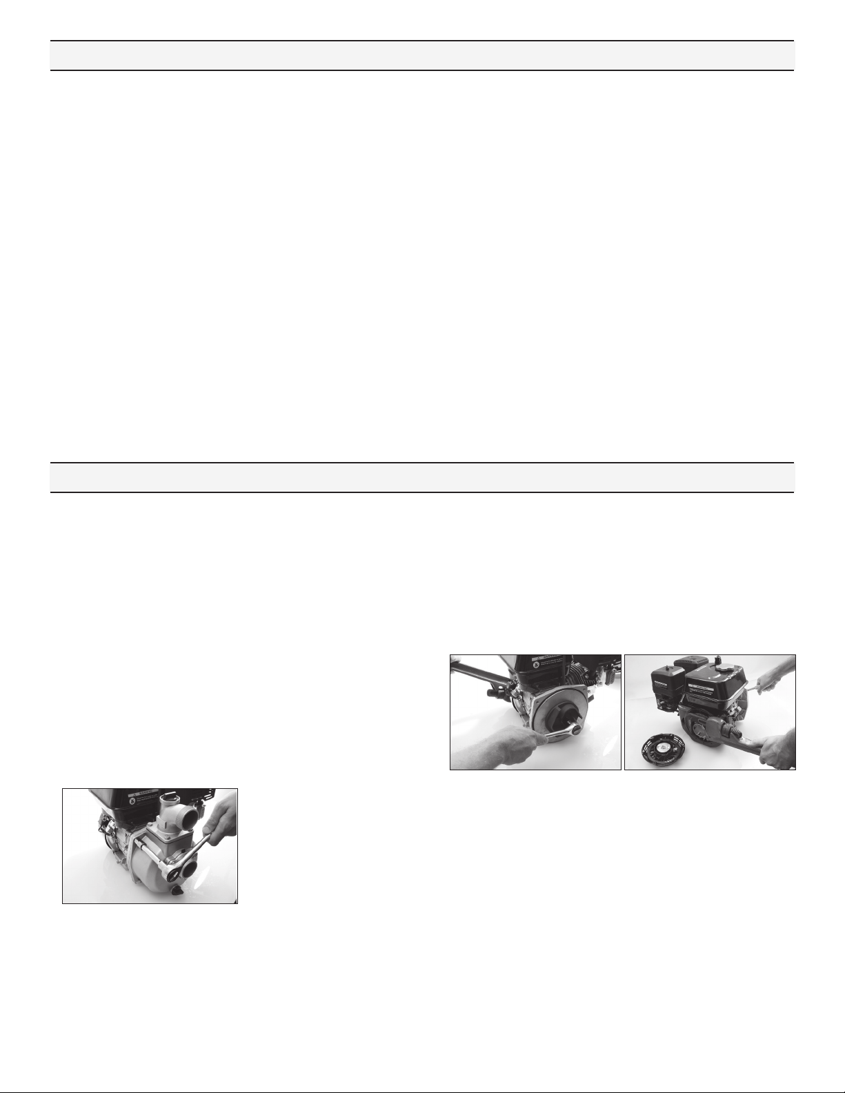
3. Remove impeller by turning the bolt counterclockwise using
a socket and impact wrench. If an impact wrench is not
available, it may be necessary to hold the cranksha from
turning. To keep the cranksha from turning during
disassembly, remove the three bolts holding the recoil
starter using a 10mm socket wrench. Then, using a pipe
wrench or another tool, hold the starter hub and turn the
impeller bolt o. Using a pry bar on each side of impeller
closest to the cranksha slide impeller o. Use caution
during the removal so to not damage the impeller. Remove
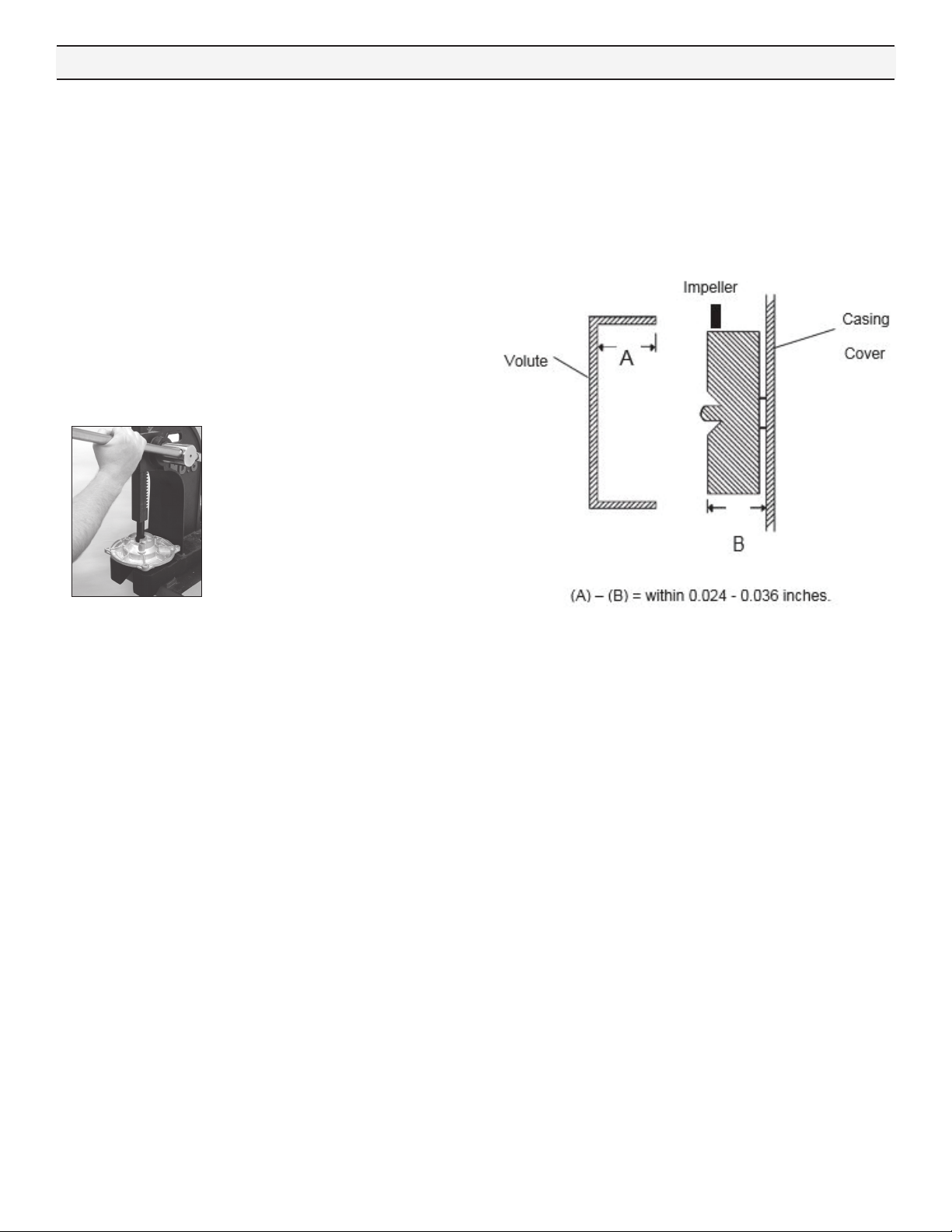
the key from cranksha keyway. Look for shims that may
be present between the impeller and sha. This shim is
for obtaining the proper clearance between the impeller
and volute. Be careful not to damage the starter hub while
gripping it with the wrench.
4. Between the impeller and casing cover is the mechanical
seal. On the backside of the impeller is the seal’s ceramic
seat. If either part of the seal is damaged, with cracked or
scued surfaces, the seal will fail to perform satisfactory
and will leak. To remove the seal seat from the impeller,
use a small blade screwdriver and wedge the seal seat out
and discard. To remove the mechanical seal, it is necessary
to first remove the casing cover by removing the four bolts
holding it to the engine, using 13mm socket wrench. Note
that these bolts have seal washers on them and must not be
damaged. From the backside of the casing cover, press the
mechanical seal out and discard it.
Repair Instructions

4
(Repair Instructions Continued)
Clean-up of Pump Housing
If necessary , clean the pump casing, volute, and casing cover
using a solvent to remove debris and corrosion particles. Use
a wire brush to further remove buildup of debris if it doesn’t
soak loose.
Seal Replacement and Pump Housing Assembly
1. Apply a light bead of RTV sealant to the top edge of the
seal cavity on the casing cover.
2. Insert the stationary portion of the new mechanical seal by
carefully pushing only on the outer metal ring as you press
it into the casing cover. Use a tool with 1 1/2” ID, such as a 1
1/2” PVC pipe, 4” long, that fits over the carbon face of the
seal, but pushes only on the metal ring to insert the seal. Be
careful to avoid scratching the seal’s carbon surface.
3. Bolt casing cover on engine. Note the arrow and word UP to
indicate orientation of the casing cover. Use bolts with
washers on them. Install o-ring on casing cover; replace with
a new o-ring if necessary.
4. Lubricate the seal cavity of the impeller with WD-40, LPS,
or equivalent, and carefully press the seal’s mating ceramic
ring in place, seating it squarely on the bottom of the
cavity. IMPORTANT: MAKE SURE BOTH OF THE SEAL’S
SURFACES ARE CLEAN AND LUBRICATED. NEVER RUN THE
SEAL SURFACES DRY.
5. Place the key into the keyway of the cranksha making sure
it is seated properly. Lubricate the cranksha slightly with
WD-40, LPS or equivalent and slide impeller on sha.
Secure the impeller.
6. It is now necessary to check the clearance between the
impeller and volute. As shown in the sketch below, measure
the inside depth of the volute case (distance A). Then
measure the distance from the casing cover to the front edge
of the impeller (distance B). The dierence between the
two measurements should be between 0.024 and 0.036” or
about 1/32” clearance. If the value is out of range, remove
the impeller and adjust by adding or removing brass shims
to achieve the correct amount of clearance.
7. Place a new o-ring in the groove of the volute’s inlet if
necessary. Place the volute in place with the notch pointing
up so that it mates with the casing cover at the inlet port.
It may be necessary to tip the engine on its side for this
assembly.
8. Carefully set casing over volute and bolt casing onto casing
cover and frame. It may be necessary to tip the engine on its
side for this assembly.
9. Once assembly is complete, pull on engine recoil starter with
engine switch in OFF position to verify that the impeller
rotates smoothly without catching. Connect spark plug wire.
Assembly and inspection is now complete.
Repair Instructions

5
Symptom Probable Cause(s) Corrective Action(s)
No discharge Pump not priming
Discharge line must be open for priming to occur. If
valve is installed, check that it is open.
Fill priming chamber with water.
Increase engine speed.
Low discharge
Air leaks in suction line Check inlet fittings for leaks. Seal leaks.
Undersized or collapsed suction hose Suction inlet hose should be same diameter as
inlet port fitting. Check hose for kinks
Blocked or clogged inlet Inspect basket strainer and clear any debris from
screen.
Impeller plugged Inspect and clear obstruction.
Fluid leaking from pump Mechanical seal failure Determine fluid is coming from weep holes
between pump and engine. Change out seal.
Crack in pump housing Check casing and casing cover for damage
Engine doesn’t run Check oil & gas Refer to engine manual for troubleshooting problem.
Troubleshooting

6
Models GNP20C, GNP30C
Ref.
No.
Qty.
Req’d. Part No. Description
1 LCT208 OPP 208CC
1 2801-0011 Frame
4 2210-0021 Bolt
4 2270-0112 Washer
4 2250-0008 Hex Nut
1 1 N/A Pump Cover
2 1 N/A O-ring 196mmx4mm
3 4 N/A Sealed Washer
4 4 N/A Hex Bolt M8x55
5 1 N/A Mechanical Seal
6 1 0400-1542 Impeller
7 1 N/A
8 1 N/A O-ring 53mmx7mm
9 1 N/A Pump Body
10 1 N/A Outlet Sealed Washer
11 11 2270-0112 Washer
12 4 19708 Hex Bolt M8x25
13 2 N/A O-ring 23x3.5mm
14 2 3240-0008 Plug
15 1 2404-0409 Outlet Flange
16 1 N/A Check Valve
17 1 2404-0405 Inlet Flange
18 7 2210-0120 Hex Bolt M8x20
19 4 N/A Clamp
20 3 3350-0174 Strainer
123456789
10
11 12 13 14
15
16 17
19
20
11 18 13 14 11 18
IMPORTANT:
When ordering parts, give PART
NUMBER and PART DESCRIPTION.
Reference Numbers are used ONLY to
point out parts in the drawing and are
NOT to be used as ordering numbers.
STANDARD SEAL KIT NO. 3430-0799
Consists of (1) Ref. 2 O-ring, (4) Reg. 3 Sealed Washers, (1) Ref.
5 Mechanical Seal, (1) Ref. 8 O-ring, (1) Ref. 10 Outlet Sealed
Washer, (2) Ref. 13 O-rings, and (1) Ref. 16 Check Valve
STANDARD SEAL KIT NO. 3430-0802
Same as standard kit but contains (1) Ref. 5 SiC mechanical seal
in place of standard carbon/ceramic.
STANDARD SEAL KIT NO. 3430-0800
Consists of (1) Ref. 2 O-ring, (4) Ref. 3 Sealed Washers, (1) Ref.
5 Mechanical Seal, (1) Ref. 8 O-ring, (1) Ref. 10 Outlet Sealed
Washer, (2) Ref. 13 O-rings, and (1) Ref. 16 Check Valve
STANDARD SEAL KIT NO. 3430-0803
Same as standard kit but contains (1) Ref. 5 SiC mechanical seal
in place of standard carbon/ceramic.
Parts List:GNP20C Parts List: GNP30C

7
1
2
3
4
5
6
7
8
9
10
11
12
13
15
14
3
2
Models GNP30T
IMPORTANT:
When ordering parts, give PART
NUMBER and PART DESCRIPTION.
Reference Numbers are used ONLY to
point out parts in the drawing and are
NOT to be used as ordering numbers.
Ref.
No.
Qty.
Req’d. Part No. Description
1 LCT208 OPP 208CC
1 2801-0012 Frame
4 2210-0021 Bolt
4 2270-0112 Washer
4 2250-0008 Hex Nut
1 1 N/A Pump Body
2 2 N/A O-ring 23x3.5mm
3 2 3240-0008 Plug
4 6 2280-0006 T-type Screw
5 6 N/A O-ring 5x2.65mm
6 1 N/A Check Valve
7 1 N/A
8 1 0402-1543 Impeller
9 1 N/A Column Pin
10 1 N/A O-ring 125x2.65mm
11 1 N/A O-ring 260x5mm
12 1 N/A Pump Cover
13 1 N/A Mechanical Seal
14 1 2404-0408 Hex Hose Joint
15 1 3350-0176 Strainer
STANDARD SEAL KIT NO. 3430-0801
Consists of (2) Ref. 2 O-ring, (1) Ref. 6 Check Valve, (1) Ref.
10 O-ring, (1) Ref. 11 O-ring, and (1) Ref. 13 Silicon Carbide
Mechanical Seal
Parts List: GNP30T
This manual suits for next models
2
Table of contents
Popular Water Pump manuals by other brands

Donjoy
Donjoy JZ1 Series Operation and maintenance manual

SPX
SPX Johnson Pump TopLobe TL1 instruction manual

Ingersoll-Rand
Ingersoll-Rand PP20A-XXX-XXX Operator's manual

Adam Pumps
Adam Pumps AF 3000 Use and maintenance instruction manual

Knauer
Knauer Azura P 4.2S instructions

Neptun
Neptun NSP-E 95 Inox Original operating instructions