G2 EV S 800 User manual

DE Page 1of 19 GB
BOILER MIT INDIREKTER ANWÄRMUNG MIT EINEM
WÄRMEAUSTAUSCHER:
ЕV (Х)S 800; 1000; 1500; 2000
BOILER MIT INDIREKTER ANWÄRMUNG MIT ZWEI
WÄRMEAUSTAUSCHER:
ЕV (Х/Х)S2 800; 1000; 1500; 2000
PUFFER UNER HOCHDRUCK:
ЕV 800; 1000; 1500; 2000
LESEN SIE DIE ANWEISUNG VOR DER MONTAGE UND VOR DER
INBETRIEBNAHME DES GERÄTS!
BEWAHREN SIE SORGFÄLTIG DAS DOKUMENT!
WATER HEATERS WITH INDIRECT HEATING WITH ONE HEAT
EXCHANGER:
ЕV (Х)S 800; 1000; 1500; 2000
WATER HEATERS WITH INDIRECT HEATING WITH TWO HEAT
EXCHANGERS:
ЕV (Х/Х)S2; 800; 1000; 1500; 2000
BUFFERS FOR DOMESTIC HOT WATER:
ЕV 800; 1000; 1500; 2000
READ THE INSTRUCTION BEFORE INSTALLING DEVICE AND PUT IT INTO
OPERATION
KEEP CAREFULLY THIS DOCUMENT!

DE Page 2of 19 GB
Sehr geehrte Kunden,
Die vorliegende technische Beschreibung und Betriebsanweisung hat
zum Zweck Sie mit dem Gerät und die Voraussetzungen zu seiner richtigen
Montage und dem Betrieb bekanntzumachen. Die Anweisung ist auch für die
geprüfte Techniker bestimmt, die das Gerät montieren, demontieren und bei
Beschädigung reparieren werden.
Das Befolgen der Vorschriften in der vorliegenden Anweisung ist im
Interesse des Käufers und ist eines von den Garantiebedingungen, die im
Garantieschein angegeben sind.
Diese Anweisung ist untrennbarer Teil des Boilers. Sie muss aufbewahrt
werden und das Gerät begleiten, wenn der Besitzer oder der Verbraucher
wechselt, und/oder aufs Neue installiert wird.
Lesen Sie die Anweisung sorgfältig. Sie hilft Ihnen eine gefahrlose
Montage, Nutzung und Instandhaltung Ihres Gerätes zu sichern.
Die Installierung des Geräts ist auf Kosten vom Käufer und soll von einem
ausgebildeten Monteur ausgeführt werden, in Übereinstimmung mit der
vorliegenden Anweisung.
Dear Clients,
The instruction manual and the technical description are prepared in
order to acquaint you with the product and the conditions of proper installation
and usage. Read them carefully and follow them.
These instructions are also intended for use by qualified technicians, who
shall perform the initial installation, or disassembly and repairs in the event of a
breakdown.
The observance of the instructions contained herein is in the interest of
the buyer and represents one of the warranty conditions, outlined in the warranty
card. The non-observance of the instruction can be reason of losing
warranty!
This manual is an integral part of the appliance. It must be kept with
care and must follow the appliance if the latter is transferred to another owner or
user and/or to another installation.
Read the instruction and tips very carefully. They will help you
secure a safe installation, use and maintenance of your appliance.
The installation is at the buyer’s expense and must be carried out by
a professional technical person from the sector in accordance with instructions in
the manual.

DE Page 3of 19 GB
I. BESTIMMUNG
Das Gerät ist bestimmt für die Haushalt - Deckung mit Heißwasser für
Objekte, die eine Hauptwasserleitung mit Druck, nicht mehr als 0,8MPa (8 bar)
haben.
Das Gerät ist bestimmt für die Nutzung in geschlossenen und beheizbaren
Räumen und ist nicht bestimmt für Arbeit bei ständig durchfließendem Betrieb.
II. BESCHREIBUNG UND TECHNISCHE DATEN
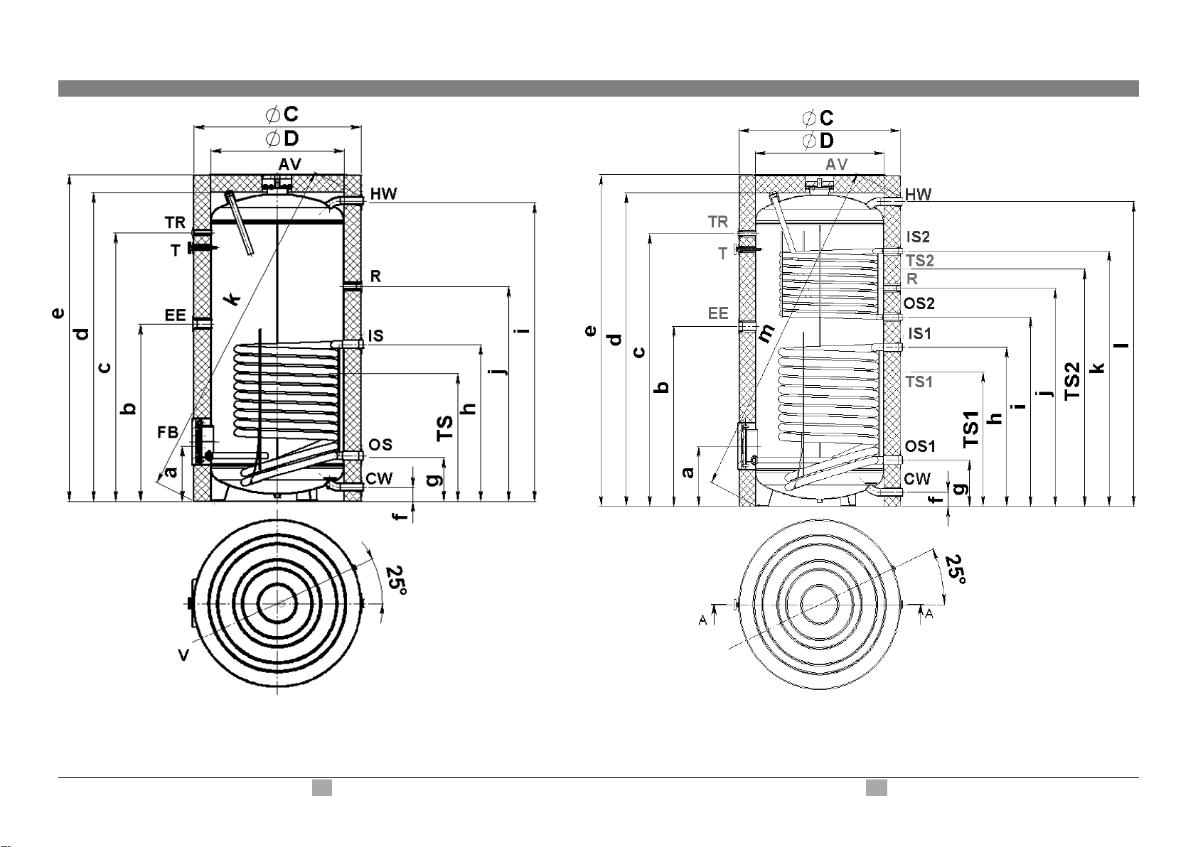
In Abhängigkeit von Modell können die Warmwasserbereiter ohne
Wärmeaustauscher oder mit einem oder mit zwei eingebauten
Wärmeaustauscher ausgeführt werden.
Zum Boiler ist ein Anzeigegerät für die Ablesung der Temperatur im
Warmwasserbereiter montiert. –T. Vorhanden sind die Röhrenausgänge
(bezeichnet mit TS1, TS2, TS3) für die Geber - Montage für
Wassertemperaturabmessung im Boiler und diese Röhrenausgänge haben eine
Mitwirkung bei der Stromleitung des Wärmeträgers durch die
Wärmeaustauscher. Zum Boiler kann man ein elektrisches Heizgerät montieren,
dafür ist einen Rohrausgang bereitgestellt, bezeichnet mit den Buchstaben EE
(HE). Rohrausgang, der mit dem Buchstaben R bezeichnet ist, ist für die
Warmwasserrezirkulation bestimmt, in Anlagen, die diese Möglichkeit bieten.
Der Boiler ist mit zwei Flanschen versichert. Der eine Flansch ist an dem
oberen Teil des Geräts gelegen, darauf ist die Anodenschutzvorrichtung
befestigt. Der zweite Flansch ist seitlich gelegen und und dient zu Prüfung und
Reinigung des Warmwasserbereiters.
ACHTUNG! Das elektrische Heizgerät muss von dem
Warmwasserbereiter-Hersteller zugestimmt werden. Anderenfalls fällt die
Gerätsgarantie aus un der Hersteller trägt keine Verantwortung bei einem
unnormalen Gerätsbetrieb.
I. INTENDED USE
The appliance is intended to supply hot water to households equipped
with a piping system working at pressure below 8 bar (0,8 MPa).
The appliance is intended for work in closed, heated premises (above 4
oC). It is not intended to work in a constant flow through regime.
II. DESCRIPTION AND TECHNICAL DATA
Depending on the model of the high capacity water heater (HCWH), it
can has one or two built-in heat exchangers (serpentines). The connections to
the high capacity water heaters should be made following the market outlets and
inlets, described below:
T- for temperature indicator (the indicator is included in the kit of the appliance)
TS1, TS2, TS3 - for mounting temperature sensors (each heat exchanger can be
controlled by temperature). If the appliance is equipped with one heat exchanger
there will be only one outlet “TS1” available.
EE (HE) –for electrical heating element - positioned in the middle of the
appliance. Follow the technical data for choosing the proper power of the heating
element.
ATTENTION: The electrical heating element should be approved from the
producer of the high capacity water heater. Otherwise the producer does
not follow any warranty conditions and it is not responsible for any
abnormal work of the appliance.
FLANGE /near the bottom/ - it can be used for mounting an electrical heating
element. Follow the technical data.
R- for hot water recirculation systems.
On the high capacity water heater you will see two flanges: one is at the top with
anode protector mount on it and the other is near the bottom, which must be
used for maintenance /cleaning/ of the water tank

DE Page 4of 19 GB
ІII. BOILER MIT „WEICHER” ISOLATION 800–2000L. III. WATER HEATERS WITH “SOFT” PU INSULATION
Typ Rohrschlange
Coil heat exchanger type:
15/9 S2
15S
12/8 S2
12S
13S
13/7 S2
12S
12/9 S2
Nominell - Volumen
Total capacity (EN 12897)
l
1928
1950
1500
1500
988
977
750
750
Volumen reell
Actual capacity (EN 12897)
l
1836
1867
1430
1455
941
931
742
730
Nettogewicht
Weight
kg
501
454
421
382
233
279
250
272
Isolation „Weich” PU
Insulation
mm
100
100
100
100
100
100
100
100
Fläche Rohrschlange (S1 -untere)
Heat exchanger surface (S1 –lower HE)
m2
4.5
4,5
3,47
3,47
3.45
3.45
2.89
2.89
Fläche Rohrschlange (S2 -obere)
Heat exchanger surface (S2 –upper HE))
m2
2.7
2,3
-
1.31
-
1.54
Volumen Rohrschlange (S1)
Heat exchanger content (S1)
l
41.6
41,6
31,4
31,4
31.3
31.3
26.2
26.2
Volumen Rohrschlange (S2)
Heat exchanger content (S2)
l
25.2
20,5
-
7.9
-
9.4
Leistung S1
im durchfließenden Betrieb
70-90°C
60-80°C
50-70°C
50-60°C
Exchanged power of HE
S1 in continuous mood
70-90°C
60-80°C
50-70°C
50-60°C
kW
250
195
130
68
250
195
130
68
175
140
100
80
175
140
100
80
175
130
85
56
175
130
85
56
148
107
70
50
148
107
70
50
Leistung S2
im durchfließenden Betrieb
70-90°C
60-80°C
50-70°C
50-60°C
Exchanged power of HE
S2 in continuous mood
70-90°C
60-80°C
50-70°C
50-60°C
kW
117
83
51
24
-
120
95
68
51
-
72
50
30
17
-
87
57
36
20
Max. Durchflußmenge Warmwasser
mit ∆T35°C (S1)
70-90°C
60-80°C
50-70°C
50-60°C
Max. flow rate of DHW with ∆T35°C
(S1); continuous mood
70-90°C
60-80°C
50-70°C
50-60°C
l/min
102
80
53
26
102
80
53
26
72
57
41
33
72
57
41
33
72
53
35
23
72
53
35
23
61
44
29
20
61
44
29
20
Max. Durchflußmenge Warmwasser
mit ∆T35°C (S2)
70-90°C
60-80°C
50-70°C
50-60°C
Max. flow rate of DHW with ∆T35°C
(S2); continuous mood
70-90°C
60-80°C
50-70°C
50-60°C
l/min
46
34
21
10
49
39
28
21
-
29
20
12
7
-
36
23
15
8
Max. Menge Wasser MIX45°C (S1)
Quantity of hot water MIX45°C (S1)
l
2080
2145
1660
1728
1081
1055
800
780
Max. Menge Wasser MIX45°C (S2)
Quantity of hot water MIX45°C (S2)
l
991
611
-
503
-
358
Wärmeverlust (∆T45K)
Heat loss (∆T45K)
kW/24h
8.3
8.3
6.5
6.5
5.3
5.3
5.1
5.1
Max. Betriebstemperatur
Max. working temperature
°C
95
95
95
95
95
95
95
95
Max. working temperature coil HE
°C
110
110
110
110
110
110
110
110
Max. Betriebsdruck Wasserbehälter
Max. pressure of water tank
MPa
0.8
0,8
0,8
0,8
0.8
0.8
0.8
0.8
Nominell Betriebsdruck Wasserbehälter
Nominal pressure of water tank
MPa
0.6
0,6
0,6
0,6
0.6
0.6
0.6
0.6
Betriebsdruck für die Rohrschlangen
Max. pressure of coil heat exchanger
MPa
0.6
0,6
0,6
0,6
0.6
0.6
0.6
0.6

DE Page 5of 19 GB
IV. BOILER TYP 750 –1000 DIMENSIONEN. IV. OVERALL DIMENSIONS TYPE: 750 –1000L
ЕV X S 750; 1000 ЕV X/X S2 750; 1000

DE Page 6of 19 GB
13S
13/7S2
12S
12/9S2
mm
1000
1000
750
750
a
354
354
351
351
b
1132
1132
1051
1051
c
1475
1475
1512
1512
d
1894
1895
1750
1750
e
2002
2002
1857
1857
f
81.5
81.5
82.5
82.5
g
272
272
269
269
h
987
987
929
929
i
1274
1174
1700
1105
j
1846
1274
1273
1273
k
2097
1475
1943
1492
l
-
1847
-
1700
m
-
2100
-
1943
TS 1
830
817
756
756
TS 2
-
1374
-
1363
ØD
850
850
790
790
ØC
1050
1050
990
990
750 - 1000
R
Eingang Rezirkulation
Recirculation
G ¾” F
TS1
Thermosensor 1
Thermo pocket1
G ½” F
TS2
Thermosensor 2
Thermo pocket 2
G ½” F
EE
elektrisches Heizgerät
Electric heating element
G 1 ½” F
T
Thermometer
Thermometer
G ½” F
TR
Thermoregler
Thermoregulator
G ½” F
CW
Eingang Kaltwasser
Inlet cold water
G 1 ½” M
IS2
Eingang Rohrschlange 2
Inlet heat exchanger 2
G 1” M
OS2
Ausgang Rohrschlange 2
Outlet heat exchanger 2
G 1”M
IS1
Eingang Rohrschlange 1
Inlet heat exchanger 1
G 1 ½” M
OS1
Ausgang Rohrschlange 1
Outlet heat exchanger 1
G 1 ½” M
HW
Ausgang Heißwasser
Outlet hot water
G 1 ½” M
AV
Entlüftung
Air ventilation
G¾” F

DE Page 7of 19 GB
V. BOILER TYP 1500 –2000 DIMENSIONEN. V. OVERALL DIMENSIONS TYPE: 1500 –2000L
ЕV X S 1500; 2000 ЕV X/X S2 1500; 2000

DE Page 8of 19 GB
15S
15/9S2
12S
12/8S2
mm
2000
2000
1500
1500
a
1927
1927
1768
1768
b
1827
1827
1666
1666
c
1287
1287
1168
1168
d
497
497
468
468
e
2399
2399
2193
2193
f
2263
2263
2061
2061
g
-
1875
-
1691
h
1560
1560
1378
1378
i
-
1537
-
1329
j
-
1380
-
1251
k
1244
1244
1081
1081
l
587
587
579
579
m
420
420
421
421
n
90
90
90
90
p
2565
2565
2361
2361
ØC
1300
1300
1200
1200
ØD
1100
1100
1000
1000
1500 - 2000
R
Eingang Rezirkulation
Recirculation
G 1 ½” F
TS1
Thermosensor 1
Thermo pocket1
G ½” F
TS2
Thermosensor 2
Thermo pocket 2
G ½” F
EE
elektrisches Heizgerät
Electric heating element
G 1 ½” F
T
Thermometer
Thermometer
G ½” F
TR
Thermoregler
Thermoregulator
G ½” F
CW
Eingang Kaltwasser
Inlet cold water
G 2” M
IS2
Eingang Rohrschlange 2
Inlet heat exchanger 2
G 1 ½” M
OS2
Ausgang Rohrschlange 2
Outlet heat exchanger 2
G 1 ½” M
IS1
Eingang Rohrschlange 1
Inlet heat exchanger 1
G 1 ½” M
OS1
Ausgang Rohrschlange 1
Outlet heat exchanger 1
G 1 ½” M
HW
Ausgang Heißwasser
Outlet hot water
G 2” M
AV
Entlüftung
Air ventilation
G¾” F

DE Page 9of 19 GB
VI. PUFFER FÜR HAUSHALT-HEIßWASSER VI. BUFFERS FOR DHW.
EV 2000
EV 1500
EV 1000
EV 750
Nominell Volumen
Total capacity (EN 12897)
І
2000
1500
1000
750
Volumen reell
Actual capacity (EN 12897)
l
1916
1492
977
755
Isolation
Insulation
mm
“Soft” PU 100
“Soft” PU 100
“Soft” PU 100
“Soft” PU 100
Max. Betriebstemperatur
Maximum operational temperature
T°C
95
95
95
95
Max. Druck
Max. pressure of water tank
MPa
0.8
0.8
0.8
0.8
Nominell Betriebsdruck
Nominal pressure of water tank
0.6
0.6
0.6
0.6
Positionen für Thermosonden
Thermopockets
pcs.
2
2
3
3
Nettogewicht
Weight
kg
388
338
211
196
750L
1000L
1500L
2000L
a
351
354
1767
1927
b
1051
1132
1665
1827
c
1502
1383
1167
1287
d
1592
1475
467
497
e
1750
1895
2193
2399
f
1857
2002
2061
2263
g
80
80
1750
1915
h
272
272
1250
1370
i
1094
1174
1080
1141
j
1273
1273
367
397
k
1512
1654
90
90
l
1700
1846
-
-
p
-
-
2214
2412
ØD
790
850
1000
1100
ØC
990
1050
1200
1300

DE Page 10 of 19 GB
EV 750; EV1000
EV1500; EV2000

DE Page 11 of 19 GB
EV 750; EV1000
EV1500; EV2000
R
Eingang Rezirkulation
Recirculation
G ¾” F
G 1 ½” F
TS1
Thermosensor 1
Thermo pocket1
G ½” F
G ½” F
TS2
Thermosensor 2
Thermo pocket 2
G ½” F
G ½” F
TS3
Thermosensor 3
Thermo pocket 3
G ½” F
-
EE
elektrisches Heizgerät
Electric heating element
G 1 ½” F
G 1 ½” F
T
Thermometer
Thermometer
G ½” F
G ½” F
TR
Thermoregler
Thermoregulator
G ½” F
G ½” F
CW
Eingang Kaltwasser
Inlet cold water
G 1 ½” M
G 2” M
HW
Ausgang Heißwasser
Outlet hot water
G 1 ½” M
G 2” M
L
Eingang Wärmequelle
Inlet heat source
-
G 2” M
AV
Entlüftung
Air ventilation
G ¾” F
G ¾” F

DE Page 12 of 19 GB
VII. MONTAGE UND ANSCHLUSS
ACHTUNG! ALLE MONTAGEARBEITEN SOLLEN VON BERECHTIGTEN
TECHNIKER AUSGEFÜHRT WERDEN.
1. MONTAGE
Die Warmwasserbereiter sind an individuellen Transportpaletten befestigt, um
ihre leichtere Beförderung. Falls der Boiler in einem Raum mit flachem Boden
und niedriger Feuchtigkeit montiert wird, dann ist es zulässig, daß die Palette
nicht weggenommen wird.
Nötigenfalls, wenn man die Palette wegnehmen muss, soll die folgende
Reihenfolge eingehaltet werden (fig.4):
-Stellen Sie das Gerät im liegenden Zustand, indem Sie vorher eine Matte
darunder legen, damit Sie ihm vor Beschädigung bewahren. Schrauben Sie die
drei Bolzen, mit denen die Palette zum Puffer befestigt ist, auf.
-Wickeln Sie die regulierbaren Zapfen auf der Stelle der Bolzen auf. *
-Stellen Sie das Gerät im vertikalen Stellung auf und nivellieren Sie, indem Sie
die Zapfenhöhe regulieren.
*Falls die regulierbaren Zapfen mehrteilig sind, bauen Sie die der Zapfen
zusammen, indem Sie die folgende Reihenfolge einhalten (fig. 5):
-Stellen Sie Detail 1 auf Bolzen 2, von der Palette entfernt
-Stellen Sie Scheibe 3, von der Palette entfernt
-Schrauben Sie fest und ziehen Sie gut die Schraubenmutter 4 fest
ACHTUNG! Um die Schaden dem Verbraucher und (oder) dritten
Personen falls Beschädigung an dem Warmwasserversorgungssystem zu
vermeiden, ist es erforderlich, daß das Gerät in Räumen mit
Bodenhydroisolation und (oder) Kanalisationsdränage montiert wird.
2. MONTAGE VON „WEICHER” ISOLATION FÜR GERÄTE VON 800 BIS 2000
LITER. Die Isolationsmontage soll von zwei Leute ausgeführt warden, in
Räumen mit Minimaltemperatur 18°С. Der Isolationsmantel soll bei dieser
Temperatur mindestens 1 Stunde temperiert sein.
Die Isolation wird gemäß Fig. 8 montiert. Nachdem der Zippverschluss
zugemacht ist, wird die obere Isolation montiert, und darauf die Kunststoff –
Dekorativ –Platte. Seitlich, auf die Boilerausgänge werden die Dekorativ –
Ringe montiert.
VII. MOUNTING AND CONNECTION
ATTENTION! Qualified technicians must perform all technical and electrical
assembly works.
1. INSTALLATION
Water heaters are delivered on an individual transport pallet. If the high
capacity water heaters are used in premises with low humidity and flat floor you
can leave the pallet as it is mount on the appliance, otherwise –please follow the
described steps bellow (fig. 4):
-Put the water heater in horizontal position;
-Unscrew the three bolts which hold the pallet to the water heater;
-Mount the adjustable feet directly to the appliance;*
-Put the high capacity water heater (HCWH) in vertical position and adjust
the level using the feet.
*If the adjustment feet are delivered in separate parts you can assemble them as
follow (fig. 5):
- put the part 1 on bolt 2 which is unscrewed from the pallet
- put the washer 3 which is removed from the pallet
- Screw on the nuts 4 which are delivered with the appliances
ATTENTION! In order to prevent injury to user and/or third persons
in the event of faults in the system for providing hot water, the appliance
must be mounted in premises outfitted with floor hydro insulation (or)
plumbing drainage.
2. MOUNTING OF “SOFT” PU INSULATION.
Should be fulfilled at room temperature above 18oC
The insulation should be stored at above mentioned temperature at least one
hour before operating! After mounting according Fig.8, assure that the zipper is
well closed and put the decorative rubber rings on inlet and outlets! Place the
plastic upper lid on the appliance

DE Page 13 of 19 GB
◄Fig.8

DE Page 14 of 19 GB
3. ANSCHLUSS DES BOILERS ZUM WASSERVERSORGUNGSNETZ
Für Modelle mit einer Rohrschlange –Fig. 6
Für Modelle mit zwei Rohrschlanden –Fig.7
Für Modelle ohne Wärmeaustauscher –der Anschluss zu der Wasserleitung
ist wie bei Boiler mit einem oder zwei Wärmeaustauscher
Wo: 1-Eingangsrohr; 2 –Sicherheitsventil; 3-Reduzierventil (bei Druck in der
Wasserleitung über 0,7MPa); 4- Rückschlagventil; 5 –Anschluss zur
Kanalisation; 6- Schlauch; 7 –Ausdähnungsgefäß (empfehlenswert); 8 –
zusätlicher Hahn für Ausgießen
Beim Anschluss des Boilers zum Wasserversorgungsnetz soll man die
Hinweis –Farbringe und Etiketts mit den entsprechenden Zeichen
berücksichtigen:
-Blauer Ring und Beschriftung „CW (I)” – Eingangskaltwasser
-Roter Ring und Beschriftung “HW (H)” – für Ausgangsheißwasser
-Schwarzer Ring und Beschriftung „R” – Rezirkulation
Es ist verbindlich, daß das Sicherheitsventil, mit dem der Boiler gekauft
ist, montiert wird. Es wird beim Eingang Kaltwasser montiert, in
Übereinstimmung mit dem Körperzeiger, der die Richtung des Eingangswassers
hinweist. Eine andere Absperrarmatur zwischen dem Ventil und dem Gerät wird
nicht zugelassen.
ACHTUNG! Wenn andere (alte) Rückschlag-Sicherheitsventile vorhanden
sind, das kann zu Beschädigung des Geräts führen und diese Ventile müssen
beseitigt werden.
Unter der Voraussetzung, daß keine Kreislaufmuffe (bezeichnet mit dem
Buchstabe“R”), Muffen für Thermosonden (bezeichnet mit den Buchstaben TS1,
TS2, TS3), Muffe für Anschluss von Heizelement (bezeichnet mit den
Buchstaben “EE (HE)”) und Muffe für Thermoregler (bezeichnet mit den
Buchstaben “TR”) benutzt werden, ist es notwendig, daß sie wasserdicht
geschlossen werden, bevor der Wasserbehälter mit Wasser gefüllt wird.
Bei Modellen ohne Wärmeaustauscher (Rohrschlangen) ist die Öffnung,
bezeichnet mit „AV” für den Anschluss der Einrichtung für Entlüftung des
Wasserbehälters bestimmt.
Das Füllen des Boilers mit Wasser wird ausgeführt, indem die Öffnungen des
Heißwasserhahnes des weitestgelegenen Mischhahns und der Hahn für die
Zuführung des Kaltwassers vom Wasserversorgungsnetz zu ihm geöffnet
werden. Nach dem Füllen soll ein ununterbrochener Wasserstrahl vom Mischer
fließen, danach können Sie den Mischhahn zuschließen.
Das Ausgießen vom Wasser aus dem Wasserbehälter wird ausgeführt, indem
Sie vorher den Absperrhahn beim Eingang des Kaltwassers zumachen. Öffnen
Sie den Warmwasserhahn des weitestgelegenen Mischhahn. Öffnen Sie den
Hahn (8) für das Ausgießen des Wassers aus dem Boiler. Falls in der Anlage
3. CONNECTION TO THE WATER SUPPLY NETWORK
Models with one heat exchanger –Fig. 6
Models with tow heat exchangers –Fig. 7
Models without heat exchangers –the same as for the models with one or two
heat exchangers
Where:
1- Inlet pipe; 2 –Safety valve; 3 –Pressure reducing device (for water main
pressure > 0,7 MPa); 4 –Non return valve; 5 - Funnel connected to the sewer
network; 6 - Hose; 7 –Expansion vessel (advisable); 8 –Additional tank drain
cock
Upon connecting the water heater to the water mains you must consider the
indicative color markings /rings/ and labels affixed to the pipes:
-Blue ring and marking „CW (I)” –cold water input
-Red ring and marking “HW (H)” – hot water output
-Black ring and marking “R” - recirculation
The mounting of the safety valve supplied with the water heater is obligatory. The
safety valve must be mounted on the cold water supply pipe, in observance of
the direction arrow stamped on its body, indicating the incoming water’s direction.
Additional stopcocks must not be mounted between the safety return-valve and
the water heater.
ATTENTION! The presence of other /old/ safety valves may lead to a
breakdown of your appliance and they must be removed.
In order that you do not use the circulation outlet “R” and the outlets for
the temperature sensors “TS1”, TS2” and “TS3” as well as the outlet for the
heating element “EE (HE)” is necessary to put an end caps before filling the
water heater with water.
For models without heat exchanger –outlet marked with “AV” is
intended for connection of air vent device which allows removing the air from the
water tank.
To fill up the water heater is necessary to open the most distant tap, used for
supplying hot waterin the installation (of the mixing-faucet) and the tap for
supplying cold water near it. When the water heater is full, from the cold water
tap will continuously run water.
In the event you must empty the water heater, first you must cut off its
power supplies. The inflow of water from the water mains must first be terminated
and the most distant hot water tap of the mixing-faucet must be opened. You can
drain the water from the water heater by lifting the safety return-valve’s lever.
Water will drain from the safety return-valve’s drainage opening. Be careful with
the running water –it may cause damages.

DE Page 15 of 19 GB
keinen solchen Hahn installiert ist, kann der Boiler ausgegossen werden, wie
es folgt:
-bei Modellen, komplettiert mit Sicherheitsventil mit Hebel –heben Sie den Hebel
auf und das Wasser wird aus der Dränagenöffnung des Ventils ausgießen.
-bei Modellen, komplettiert mit Ventil ohne Hebel - kann der Boiler direkt aus
dem Eingangsrohr ausgegossen werden, indem der Boiler vorher von der
Wasserleitung abgetrennt wird.
Falls der Druck im Wasserversorgungsnetz über 0,7 MPa (7 bar) ist, ist es
erforderlich, daß ein Reduzierventil montiert wird, sonst kann der Boiler nicht
richtig ausgenutzt werden. Der Hersteller trägt keine Verantwortung für die
folgende Probleme wegen falscher Nutzung des Geräts. Unter der
Dränagenöffnung des Sicherheitsventils soll man ein Rohr montieren, das an die
Abwasserkanalisation oder an ein spezielles Abwassersystem angeschlossen
werden muss. Das Rohr muss über ausreichende Gefälle für Wasserabfluss
verfügen. Die beiden Ränder sollen zu der Atmosphäre offen sein und gegen
Erfrieren versichert sein.
In the event that the water mains piping pressure exceeds the pressure
of 0.7 MPa (7 bar), it shall be necessary to mount a pressure-reducing device;
otherwise the water heater shall not function correctly. The Manufacturer does
not assume any liability for problems arising out of the appliance’s improper use.
The draining outlet of the safety valve must be connected with drainage system.
The connection should be open in order to keep always open the outlet of the
safety valve to the atmosphere. The draining system must be protected from
freezing

DE Page 16 of 19 GB
Fig. 7▲
Fig. 6

DE Page 17 of 19 GB
VIII. KORROSIONSSCHUTZ - MAGNESIUMANODE
Der Magnesium Anodenprotektor beschützt zusätzlich die innere Fläche des
Wasserbehälter vor Korrosion. Er ist ein Verschleißelement und unterliegt, einer
regulären Auswechselung.
Mit Rücksicht auf den langfristigen und störungsfreien Betrieb Ihres Boilers
empfehlt der Hersteller periodische Prüfung vom Zustand der Magnesium –
Anode von einem berechtigten Techniker und Auswechselung nötigenfalls, das
kann bei der periodischen Prophylaxe des Geräts ausgeführt werden. Für die
Auswechselung wenden Sie sich an die bevollmächtigten Service - Personen.
IX. ARBEIT MIT DEM GERÄT
Vor dem Anfangsbetrieb des Geräts versichern Sie sich, daß der Boiler
richtig angeschlossen ist, mit der passenden Anlage und voll mit Wasser.
Alle Einstellungen, betreffs des Gerätsbetriebs werden von einem
ausgebildeten Fachmann ausgeführt.
X. WICHTIGE REGELN
Die Ausnutzung des Geräts zu Ziele, anders als seine Bestimmung sind
verboten.
Vor der Inbetriebnahme des Warmwasserbereiters versichern sie sich, daß
der Wasserbehälter voll mit Wasser ist.
Die Installierung und der Service des Geräts sollen von einem
ausgebildeten Monteur, in Übereinstimmung mit der Hersteller-Anweisungen,
ausgeführt werden.
Der Boiler soll nur in Räumen mit einer normalen Feuersicherheit montiert
werden. An der Abwasser –Anlage soll ein Siphon auf dem Boden montiert
werden. Der Raum soll gegen inneren Temperaturrückgang unter 4°С versichert
sein.
Der Boiler –Anschluss zum Wasserleitungs,- und Wärmeverrsorgungsnetz
darf nur von berechtigten Techniker ausgeführt werden. Wenn eine Gefahr
besteht, daß die Temperatur im Raum unter 0 оС zurückgeht, soll der Boiler
ausgegossen werden, indem der Hebel des Rücklauf –Sicherheitsventils
aufgehoben wird.
Beim Betrieb (Regime - Wassererwärmung), ist es normal, daß Wasser aus
dem Öffnung für das Ausgießen des Sicherheitsventils tropft. Das Ventil soll
offen zu der Atmosphäre bleiben.
Für den gefahrlosen Betrieb des Boilers, soll das Rücklauf –
Sicherheitsventil regelmäßig gereinigt und geprüft werden, ob es normal
funkzioniert, /ob es nicht blockiert ist/, in Gebiete mit stark Kalkwasser soll es von
dem gesammelten Kalkstein gereinigt werden. Diese Dienstleistung ist kein
Gegenstand des Garantieservice.
VIII. PROTECTION AGAINST CORROSION - MAGNESIUM ANODE
The magnesium anode protects the water tank’s inner surface from
corrosion. The anode element is an element undergoing wear and is subject to
periodic replacement.
In view of the long-term and accident free use of your water heater, the
manufacturer recommends periodic inspections of the magnesium anode’s
condition by a qualified technician and replacement whenever required, and this
could be performed during the appliance’s technical preventive maintenance.
For replacements, please contact the authorized service stations!
IX. OPERATING MODE
Before using the water heater make sure that the appliance is connected with the
heating installation in correct way and is filled with water.
X. IMPORTANT RULES
The use of the appliance for any purpose other than that it is
intended is prohibited.
Do not switch on the water heater unless you established it was
filled with water.
The installation and maintenance must be carried out by a
professional from the sector in accordance with manufacturer’s instructions.
The water heater must only be installed in premises with normal fire
resistance. There should be a siphon connected to a plumbing drainage. The
premises should be protected from freezing and the temperature should never be
lower than 4 °C.
Qualified P&P specialists and Electricians must only perform the connecting of
the water heater to the water main, local or central water heating, solar panel and
electric mains.
If the probability exists for the premise’s temperature to fall below
0°C, the water heater must be drained via raising the safety return-valve’s lever.
During use (water heating mode), the dripping of water from the
safety return-valve’s drainage opening is normal. The same must be left open to
the atmosphere.
In order to secure the water heater’s safe operation, the safety return-
valve must undergo regular cleaning and inspections for normal functioning /the
valve must not be obstructed/, and for the regions with highly calcareous water it
must be cleaned from the accumulated lime scale. This service is not provided
under warranty maintenance.

DE Page 18 of 19 GB
Falls beim Aufheben des Ventilhebels beim vollen Wasserbehälter aus der
Dränageöffnung kein Wasser fließt, ist das ein Signal für Beschädigung und die
Gerätausnutzung soll abgebrochen werden.
Dieses Gerät hat nicht die Bestimmung von Leuten (inkl. Kinder) mit
reduzierten physischen, empfindlichen oder geistigen Fähigkeiten benutzt
werden, oder Leute mit keiner Erfahrung und Kenntnisse, außer wenn sie
beobachtet sind oder von einer Person, verantwortlich für ihre Sicherheit, in
Übereinstimmung mit der Gerätbenutzung, instruktiert sind.
Die Kinder sollen beobachtet werden, damit es sicher ist, daß sie mit dem
Gerät nicht spielen.
Es ist notwendig, daß die Prophylaxeregeln eingehaltet werden, Ersatz
von Anodenschutzvorrichtung und Beseitigung von dem gesammelten Kalkstein,
auch nach dem Ablauf der Garantiefrist des Gerätes.
XI. REGULÄRE WARTUNG
Beim normalen Boilerbetrieb, unter der Einwirkung der hochen Temperatur
wird Kalkstein abgelagert. Deswegen empfehlt der Hersteller des Geräts jedes
zweites Jahr eine Prophylaxe des Puffers von einem bevollmächtigten
Servicezentrum oder Servicepunkt. Diese Prophylaxe soll die Reinigung und die
Prüfung von dem Anodenprotektor umfassen. Der Anodenprotektor soll
nötigenfalls mit einem neuen ausgewechselt werden. Jede solche Prophylaxe
soll im Garantieschein angegeben werden, indem Ausführungsdatum, Ausführer
–Firma, Name der Person –Ausführer und Unterschrift angegeben werden.
Die Nichterfüllung der obigen Anforderung kann die kostenlose
Garantiewartung Ihres Boilers einstellen.
Der Herstelelr trägt keine Verantwortung für alle Ergebnisse, in Folge
Nichteinhaltung der vorliegenden Anweisung.
If upon lifting the valve’s lever when the water tank is full, water
commences to flow from the valve’s drainage opening, this is a signal of
malfunction and the appliance’s use must be discontinued.
This appliance is not intended for use by persons (including children)
with reduced physical, sensory or mental capabilities, or lack of experience and
knowledge, unless they have been given supervision or instruction concerning
use of the appliance by a person responsible for their safety.
Children should be supervised to ensure that they do not play with
the appliance.
It is necessary to maintenance the water heater regarding the
described rules, to change duly the anode protector and to clean the limestone
also after the warranty period.
It is necessary to keep the rules for preventive maintenance,
replacement of magnesium anode protector and cleaning even after guarantee
period.
XI. PERIODIC MAINTENANCE
Under normal use of the heater, under the influence of high temperature, lime
scale /the so-called lime scale layer/ is deposited upon the heating element’s
surface. This worsens the heat exchange between the heating element and
water. Due to these facts, the manufacturer recommends preventive
maintenance of your water heater every two years by an authorized service
center or service base. This protective maintenance must include cleaning and
inspection of the anode protector (for water heaters with glass-ceramic coating),
which shall be replace with a new one if need arises. Each preventive
maintenance of the said type must be entered in the appliance’s warranty card
and must outline date of performing the preventive maintenance, company
performing the preventive maintenance, name of person performing the
preventive maintenance, and signature.
Non-fulfilment of the above requirement may terminate the free of charge
maintenance of your boiler.
THE MANUFACTURER DOES NOT BARE THE RESPONSIBILITY
FOR ALL CONSEQUENCES CAUSED BY NOT OBEYING THE
INSTRUCTIONS, GIVEN HEREBY.

DE Page 19 of 19 GB
0
25
50
75
100
125
150
175
200
225
250
010 20 30 40 50 60 70 80 90 100
Pressure drop, mBar
Flow rate , l/min]
EV 13/7 S2 1000 (UPPER HE)
0
10
20
30
40
50
60
70
80
90
100
010 20 30 40 50 60 70
Pressure drop [mBar]
Flow Rate [L/min]
EV 12/9 S2 750 (UPPER HE)
0
50
100
150
200
250
300
350
400
450
500
550
600
010 20 30 40 50 60 70 80 90 100
Pressure drop , mBar
Flow rate , l/min]
EV 13/7 S2 1000 (LOWER HE) and EV 13S 1000
0
50
100
150
200
250
300
350
400
010 20 30 40 50 60 70
Pressure drop [mBar]
Flow Rate [L/min]
EV 12/9 S2 750 (LOWER HE) and EV 12 S 750
0
50
100
150
200
250
300
350
400
025 50 75 100 125 150
Pressure drop [mBar]
Flow Rate [L/min]
EV 12/8 S2 1500 (Upper HE)
0
100
200
300
400
500
600
700
800
900
025 50 75 100 125 150 175 200
Pressure drop [mBar]
Flow Rate [L/min]
EV 12/8 S2 1500 (LOWER HE) and EV 12 S 1500
This manual suits for next models
19
Table of contents
Popular Water Heater manuals by other brands

PrecisionTemp
PrecisionTemp ShowerMate-550 user manual

Bradford White
Bradford White U65L155E N Series Service manual

Raypak
Raypak RAYTHERM 133-4001 Installation & operating instructions

Morco
Morco EUP11 User, installation, and maintenance manual

GE
GE 50M06AAG Energy guide

Rubine
Rubine CETUS Series user manual