G4S Patrol Suite PMD Owner's manual
G4S Justice Services, Inc.
PATROL SUITETM RF Monitoring
Equipment Guide Supplement
Portable Monitoring Device (PMD)
©2009 G4S Justice Services, Inc.
2000 RiverEdge Parkway NW, Suite GL-100
Atlanta, GA 30328, USA
1-800-589-6003

Patrol Suite RF Equipment Guide Supplement for Portable Monitoring Device (PMD)
Patrol Suite RF PMD, DCN 107
First Edition (May 2009)
Patrol Suite RF™, Web Patrol II™, and various software icons are worldwide registered trademarks of
G4S. The software described herein has U.S. and Foreign Patents Issued and Pending.
G4S provides this publication as is, without warranty of any kind, either express or implied, including, but
not limited to, the implied warranties of merchantability or fitness for a particular purpose.
This publication could include technical inaccuracies or typographical errors. Changes are periodically
made to the information contained herein; these changes will be incorporated in new editions of the
publication. G4S may make improvements and/or changes to the products described in this publication
at any time.
Reproduction of this document is expressly forbidden.
© 2009 G4S Justice Services, Inc. All rights reserved.

Patrol Suite RF Equipment Guide Supplement for PMD
Patrol Suite RF PMD DCN 107 Securing Your World iii
Table of Contents
Chapter 1 Patrol Suite RF Portable Monitoring Device (PMD).....................................................................1
Accessories...............................................................................................................................................1
Preparing the PocketPC............................................................................................................................1
PMD Operating Modes..............................................................................................................................1
PMD LED Indicators..................................................................................................................................2
Pairing the PMD and PocketPC................................................................................................................3
PocketDTX Application .............................................................................................................................6
Chapter 2 Using the PMD and PocketPC.....................................................................................................7
Chapter 3 Range Test with the PMD and PocketPC....................................................................................9
Chapter 4 Caring for the PMD and PocketPC ............................................................................................11
Chapter 5 Troubleshooting Tips..................................................................................................................12
Chapter 6 Regulatory Notices.....................................................................................................................14
Patrol Suite RF Equipment Guide Supplement for PMD
Patrol Suite RF PMD DCN 107 Securing Your World 1
Chapter 1 Patrol Suite RF Portable Monitoring Device (PMD)
The Portable Monitoring Device (PMD) is a hand-held receiver unit that
detects Patrol Suite RF PTX signals that are within range and transmits this
information to a PocketPC for viewing. This portable, battery operated
device can be used to identify participants that are wearing Patrol Suite RF
PTXs in a location away from the home and determine the condition of the
PTX. The PMD provides a remote, discrete, and safe means of verifying the
PTX presence without interfering with the participant. Additionally, the PMD
operates as an Officer Personal Identification Device (OPID) and can be
used to activate a PTX.
Accessories
The following accessories are available:
•Power Adaptor/Charger Cable
•Auto-Cigarette Lighter Charger Cable
•Pair of NiMH AA Batteries
•PocketPC Software Application
•PocketPC Application Installation
Preparing the PocketPC
To load the application onto the PocketPC:
1. Download and install the latest version of Microsoft ActiveSync on the workstation or laptop from
Microsoft’s web site: http://www.microsoft.com/downloads/details.aspx?FamilyID=7269173a-28bf-
4cac-a682-58d3233efb4c&displaylang=en.
2. Ensure that Microsoft .NET Compact Framework 2.0 Redistributable is installed on the PocketPC
2003/Windows Mobile device. If not, it can be downloaded from Microsoft’s web site:
http://www.microsoft.com/downloads/details.aspx?familyid=9655156b-356b-4a2c-857c-
e62f50ae9a55&displaylang=en.
3. Save the supplied PocketDTX_SmartDeviceCab.cab file to any location on the workstation or laptop.
4. Copy the above .cab file to any location on the Windows Mobile device using ActiveSync.
5. On your PocketPC/Windows Mobile device, run the above .cab file by clicking on it. This will install
the G4S PocketDTX application on the device. A shortcut to the PocketDTX application is created
under Start=>Programs (It uses the G4S icon).
PMD Operating Modes
The device has four operating modes controlled by a rotary switch:
•Off Mode – In Off mode the PMD is powered down.
•Wake Mode – Used to activate PTXs. In Wake mode the 433MHz Receiver
and the Bluetooth Transceiver are disabled and the PMD LED flashes
green. Periodically, the PMD also transmits wake-up commands using the
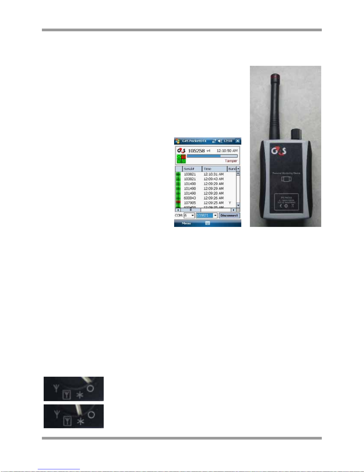
Figure 1: PocketPC Application Figure 2: PMD

Patrol Suite RF Equipment Guide Supplement for PMD
Patrol Suite RF PMD DCN 107 Securing Your World 2
internal 13.56MHz transmit coil. To activate the PTX:
1. Place the PTX face down on the front of the PMD (over the image of the
Personal Monitoring Device).
2. Listen for activation tones from PTX 1.0 or LED flashing from PTX 2.0.
•Internal Antenna Mode – In Internal Antenna mode the PMD listens for
Patrol Suite RF messages using the internal 433MHz antenna. Any
messages that are received are forwarded to the paired Bluetooth device
using the Serial Port Profile. The PMD LED indicates the state of the
Bluetooth link (i.e. the presence of a paired device).
•External Antenna Mode – External Antenna mode is exactly the same as
Internal Antenna mode except that the PMD listens for Patrol Suite RF
messages using the external antenna.
OPID functionality is enabled in Wake, Internal Antenna, and External Antenna modes. In these modes,
the PMD regularly transmits OPID RF messages using the internal 433MHz antenna. An active and
authorized OPID must be present for the user to access the PHMU Setup Menu with the PHMU Menu
Key.
NOTE: PMD can be charged in any mode (including Off Mode) by connecting the USB power, the battery
LED will indicate the charging status.
PMD LED Indicators
Status information is displayed using dual bi-color (red/green) LEDs.
The top LED, labeled with a Bluetooth symbol, displays PMD status.
The bottom LED, identified with a battery symbol, displays Battery status.
PMD Status (Bluetooth Symbol)
Mode Bluetooth PMD Indicator
Off None Off
Wake None Flash Green (Green indicates that a wake-up
command is being transmitted)
Internal Antenna No Link
Link
Blink Red and Orange
Blink Red and Green
External Antenna No Link
Link
Blink Orange
Blink Green
Battery Status (Battery Symbol)
USB Battery BAT Indicator
Powered Charging
Charged
Fault
Orange
Green
Alternate Green and Orange

Patrol Suite RF Equipment Guide Supplement for PMD
Patrol Suite RF PMD DCN 107 Securing Your World 3
No Power Good
Low
Off
Blink Red
Pairing the PMD and PocketPC
NOTE: Steps may vary depending on the model of PocketPC used.
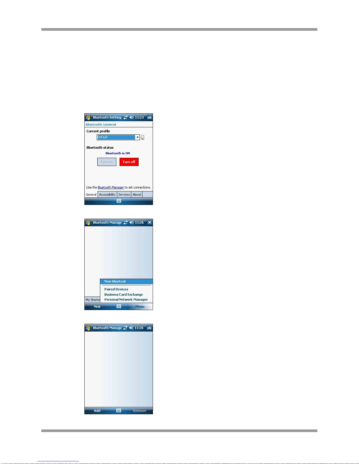
1. Ensure that the PocketPC / Windows Mobile device has a Bluetooth interface and that it is enabled.
a. From the Start Menu, select Settings
b. Select Connections and Bluetooth
c. Confirm Bluetooth Status is On
Patrol Suite RF Equipment Guide Supplement for PMD
Patrol Suite RF PMD DCN 107 Securing Your World 4
2. Be sure you have Serial Port Service enabled on your device in the Bluetooth Settings Services
tab. Depending on the device model, the serial COM port used by the Bluetooth connection may be
different. Each device usually uses a separate COM port for inbound and outbound connections. To
determine the COM port used by your device for Bluetooth connections, select Bluetooth Settings
Services=> Serial Port Service=>Advanced…. Note the outbound COM port number. You will
need to specify this COM port number in the PocketDTX application.
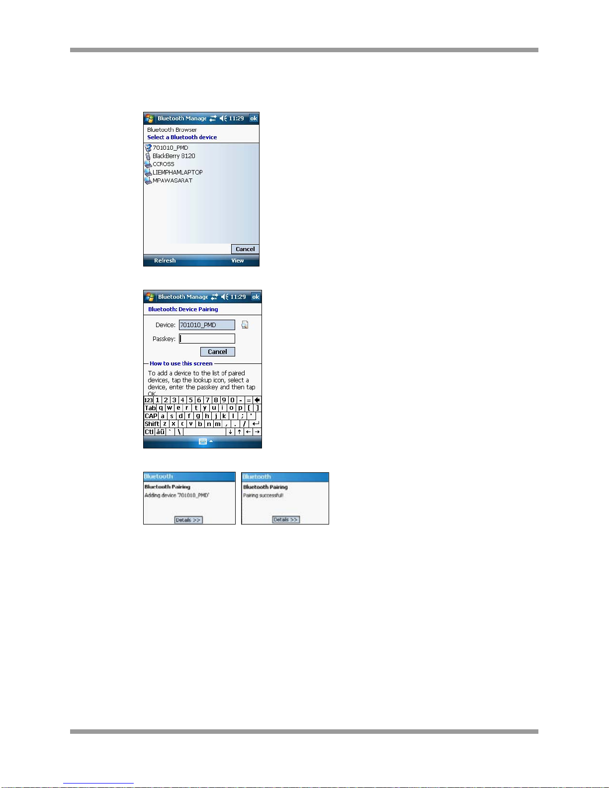
3. Explore and detect the DTX Bluetooth module using the Bluetooth Manager on your device. Ensure
that the PMD is set to Internal or External Antenna Mode.
a. From Bluetooth Settings, select Bluetooth Manager
b. Select Menu and Paired Devices
c. From Paired Devices, select Add
Patrol Suite RF Equipment Guide Supplement for PMD
Patrol Suite RF PMD DCN 107 Securing Your World 5
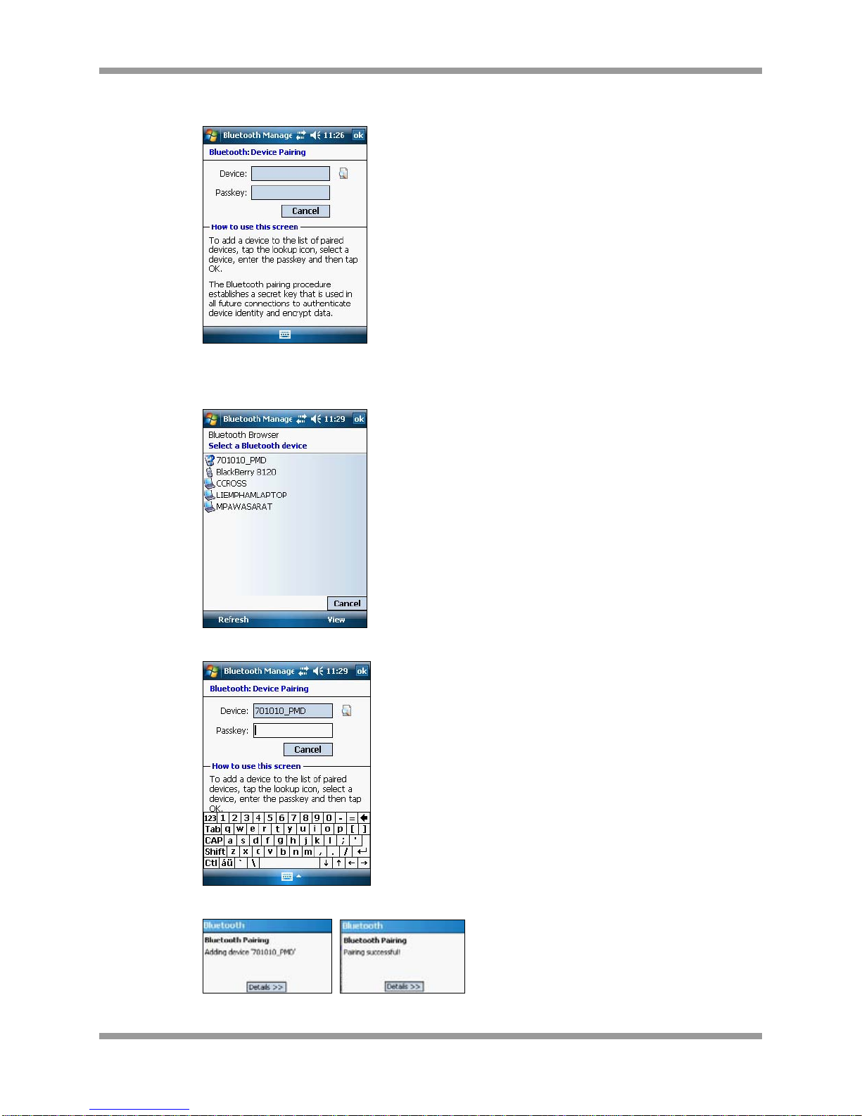
d. From Bluetooth Device Pairing, select the Search icon (next to the Device field)
e. Select the PMD serial number from the list of Bluetooth devices. If the serial number is
not displayed, reconfirm the serial number of the PMD, that the device is set to Internal or
External Antenna Mode and select Refresh.
f. Enter the passkey (typically a sequence of zeros: 0000) and Enter
g. The PocketPC provides an indication of pairing and success. If unsuccessful, retry,
Patrol Suite RF Equipment Guide Supplement for PMD
Patrol Suite RF PMD DCN 107 Securing Your World 6
4. If prompted to select which services should enabled, select Serial Port. The DTX Bluetooth module
should be added as a shortcut to your Bluetooth connection shortcuts.
5. You can now start the G4S PocketDTX application from the shortcut created under Start =>
Programs (It uses the G4S icon).
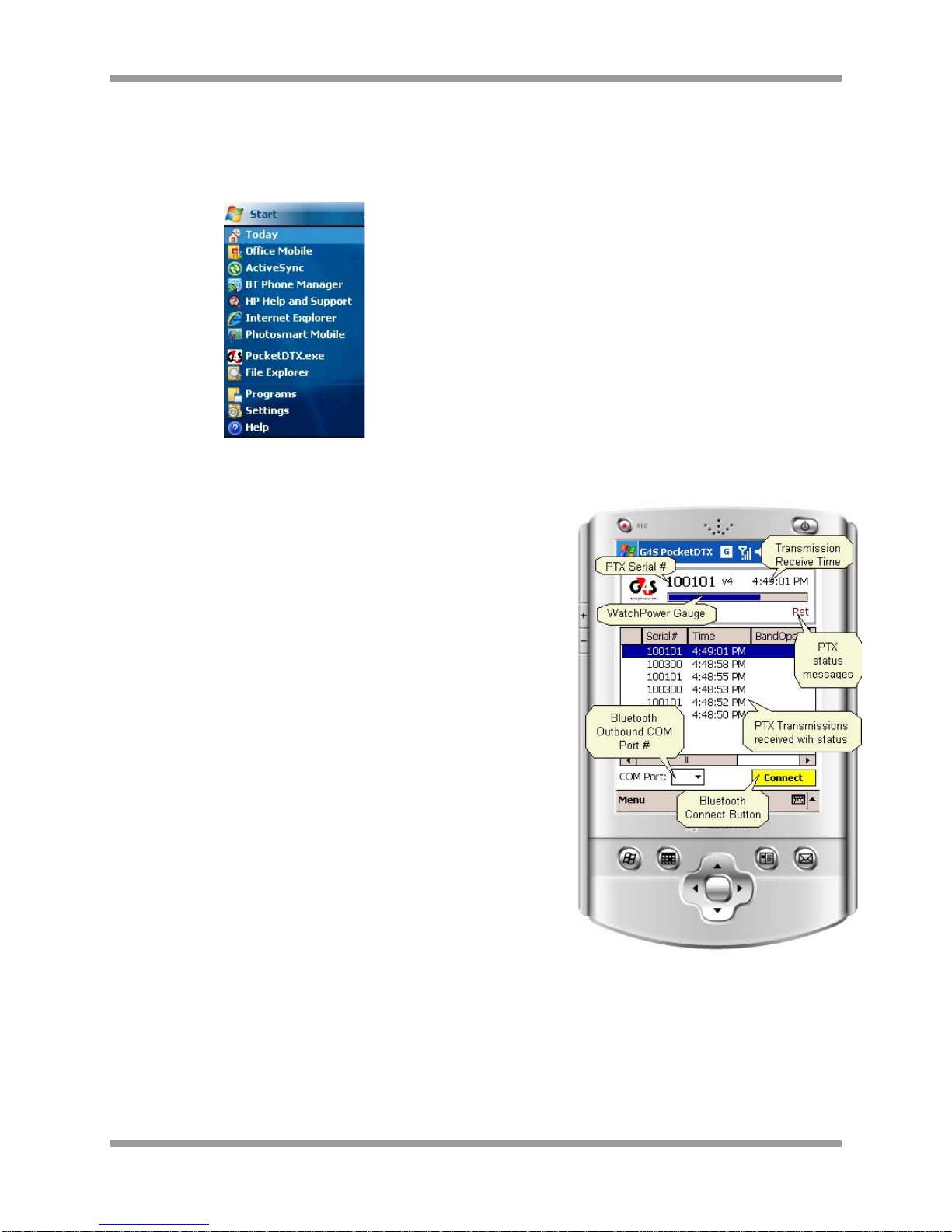
PocketDTX Application
The screen is divided into two parts:
•The main display panel at the top of the screen
•A list view in the main body.
The main display panel contains information about the last PTX
transmission received by the PMD. This includes the PTX serial
number, its message version number, the time that the
transmission was received, a gauge indicating the PTX power,
and status messages (Band Open, Tamper, Low battery, and
Restart).
The list view displays the last 100 PTX transmissions received
with the most recent on top. Each row represents a separate
transmission. The columns are PTX serial number,Time of
transmission, Band Open,Tamper, Battery Low, Restart,
Message Version, and PTX Power (Range Setting).
To connect to the DTX Bluetooth module:
1. Select the appropriate outbound Bluetooth serial COM port
number from the drop-down combo-box at the bottom left of
the screen and then select Connect. The Bluetooth browser
window should open (provided you have not previously
selected to always connect to a specific Bluetooth device)
prompting you to select the appropriate Bluetooth device to
connect to.
2. Choose the DTX Bluetooth module. If the Bluetooth connection is successful, the Connect button
changes color from yellow to light blue and the text displayed changes to Disconnect. If the PMD
detects any PTX sending status messages, they will be displayed on the main display panel and in
the list view.

Patrol Suite RF Equipment Guide Supplement for PMD
Patrol Suite RF PMD DCN 107 Securing Your World 7
Chapter 2 Using the PMD and PocketPC
1. Ensure that the PMD is set to Internal or External Antenna Mode.
2. You can now start the G4S PocketDTX application from the shortcut created under Start =>
Programs (It uses the G4S icon).
3. Select the appropriate COM port (typically Port 6), and Connect.
4. If the Bluetooth connection is successful, the Connect button changes color from yellow to light blue
and the text displayed changes to Disconnect. If the Bluetooth connection is unsuccessful, attempt
another COM port. If the PMD detects any PTX sending status messages, they will be displayed on
the main display panel and in the list view.

Patrol Suite RF Equipment Guide Supplement for PMD
Patrol Suite RF PMD DCN 107 Securing Your World 8
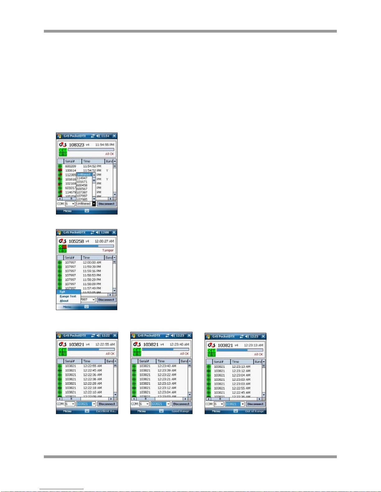
All four quadrants Green indicates All OK.
Top Left quadrant Red indicates Band Open at transmission.
Top Right quadrant Red indicates PTX is in Band Tamper.
Multiple quadrants can be red simultaneously. Bottom Right
quadrant Red indicates PTX recently reset.
Bottom Left quadrant Red indicates PTX Low Battery.
The Blue Bar indicates Power Level which represents PTX range setting. A corresponding numeric value
is visible if you scroll the list view in the main body to the right.
0 – PTX is set to Low range
5 – PTX is set to Med range
10 – PTX is set to High range or serial number represents another PMD/OPID
5. To end, select Disconnect, once disconnected the box will turn yellow and read Connect.
6. Turn Off the PMD.
Patrol Suite RF Equipment Guide Supplement for PMD
Patrol Suite RF PMD DCN 107 Securing Your World 9
Chapter 3 Range Test with the PMD and PocketPC
To conduct a range test using the PMD:
1. Ensure that the PMD is set to Internal or External Antenna Mode.
2. Start up the PocketPC.
3. From the Start Menu, open the G4S PocketDTX.exe application.
4. Select COM port and Connect. Once connected, the box will turn gray and read Disconnect.
5. Select the PTX serial number to be range tested from the dropdown.
6. Select Menu then Range Test.
7. Perform the Range Test. The PocketPC beeps will correspond to the PTX beeps and the status will
display on the PDA (lower right corner).
8. To complete the range test, select Menu then Range Test.
Excellent Ran
g
e Good Ran
g
e Out of Ran
g
e

Patrol Suite RF Equipment Guide Supplement for PMD
Patrol Suite RF PMD DCN 107 Securing Your World 10
9. Select Unfiltered from the drop-down menu.
10. Select Disconnect; once disconnected the box will turn yellow and read Connect.
11. Reinsert the Menu Key in the back of the HMU and select the red button to end.

Patrol Suite RF Equipment Guide Supplement for PMD
Patrol Suite RF PMD DCN 107 Securing Your World 11
Chapter 4 Caring for the PMD and PocketPC
The PMD should be turned off when not in use.
•Battery Life is 22-28 hours (depending on operational mode)
•Low battery indicator provides approximately 5 hours low battery warning.
•Total time taken to fully charge the batteries from a complete discharge state is approximately 6.5
hours.
Keep the PMD and PocketPC away from water as it may damage the devices.

Patrol Suite RF Equipment Guide Supplement for PMD
Patrol Suite RF PMD DCN 107 Securing Your World 12
Chapter 5 Troubleshooting Tips
If you encounter an Error establishing Bluetooth connection:
1. Ensure the PMD is set to Internal or External Antenna mode.
2. Attempt all other COM ports.
3. Confirm Bluetooth Status is On.
a. From the Start Menu, select Settings
b. Select Connections and Bluetooth
4. Confirm PMD serial number is paired with PocketPC device.
a. From Bluetooth Settings, select Bluetooth Manager
b. Select Menu and Paired Devices
c. If the PMD serial number is displayed and/or incorrect, select the serial number, Remove,
and Yes.
d. If the PMD serial number is not displayed, or if you have removed the serial number,
select Add.
e. From Bluetooth Device Pairing, select the Search icon (next to the Device field)
Patrol Suite RF Equipment Guide Supplement for PMD
Patrol Suite RF PMD DCN 107 Securing Your World 13
f. Select the PMD serial number from the list of Bluetooth devices. If the serial number is
not displayed, reconfirm the serial number of the PMD, that the device is set to Internal or
External Antenna Mode and select Refresh.
g. Enter the passkey (typically a sequence of zeros: 0000) and Enter
h. The PocketPC provides an indication of pairing and success. If unsuccessful, retry,

Patrol Suite RF Equipment Guide Supplement for PMD
Patrol Suite RF PMD DCN 107 Securing Your World 14
Chapter 6 Regulatory Notices
This device complies with Part 15 of the FCC Rules. Operation is subject to the following two conditions:
(1) this device may not cause harmful interference, and
(2) this device must accept any interference received, including interference that may cause
undesired operation.”
NOTE: This equipment has been tested and found to comply with the limits for a Class B digital device,
pursuant to Part 15 of the FCC Rules. These limits are designed to provide reasonable protection against
harmful interference in a residential installation. This equipment generates, uses and can radiate radio
frequency energy and, if not installed and used in accordance with the instructions, may cause harmful
interference to radio communications. However, there is no guarantee that interference will not occur in a
particular installation. If this equipment does cause harmful interference to radio or television reception,
which can be determined by turning the equipment off and on, the user is encouraged to try to correct the
interference by one or more of the following measures:
-- Reorient or relocate the receiving antenna.
-- Increase the separation between the equipment and receiver.
-- Connect the equipment into an outlet on a circuit different from that to which the receiver is connected.
-- Consult the dealer or an experienced radio/TV technician for help.
CAUTION: Changes or modifications to this device, not expressly approved by G4S, could void your
authority to operate this device under FCC regulations.
Table of contents
Popular Measuring Instrument manuals by other brands


Innerspec
Innerspec ROLLMATE installation instructions

Schonstedt Instrument
Schonstedt Instrument MAC-51Bx instruction manual

TFA
TFA 98.1105 instruction manual

LANDTEC
LANDTEC FPM-2680 quick start guide

Agilent Technologies
Agilent Technologies PNA Series Installation note

BIOPAC Systems
BIOPAC Systems MP41 Hardware guide