Pub. 42004-792L2A
G A I - T R O N I C S
®
A H U B B E L L C O M P A N Y
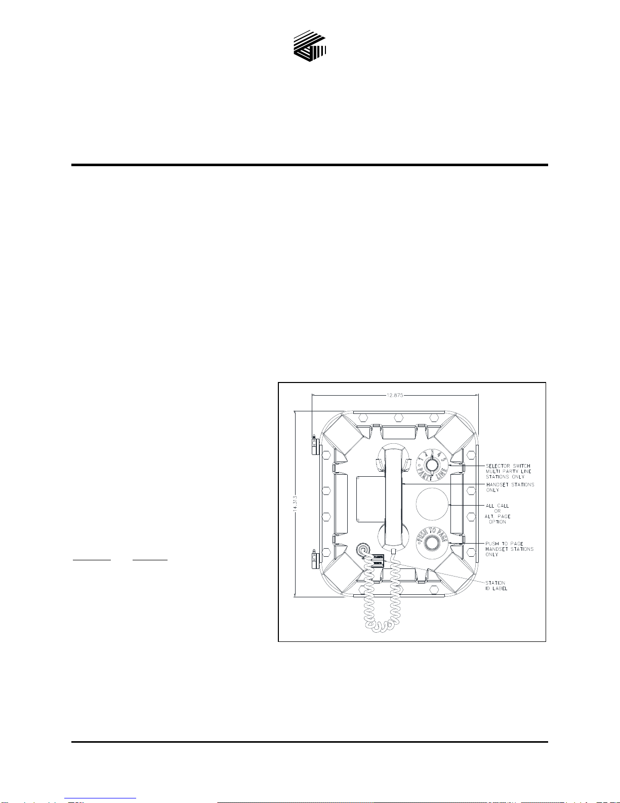
SP2 Fiber Hazardous-Area
Handset/Speaker Amplifier Station
TA B L E O F CO N T E N T S
GAI-TRONICS 3030 KUTZTOWN RD. READING, PA 19605 USA
610-777-1374 800-492-1212 Fax: 610-796-5954
VISIT WWW.GAI-TRONICS.COM FOR PRODUCT LITERATURE AND MANUALS
Confidentiality Notice.....................................................................................................................1
General Information.......................................................................................................................1
Product Overview ...................................................................................................................................1
Features....................................................................................................................................................2
Options.....................................................................................................................................................2
Installation ......................................................................................................................................3
Important Safety Instructions................................................................................................................3
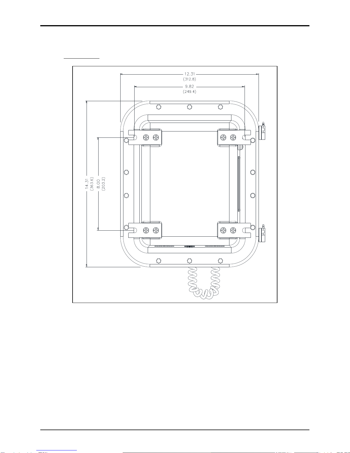
Mounting the Enclosure.........................................................................................................................4
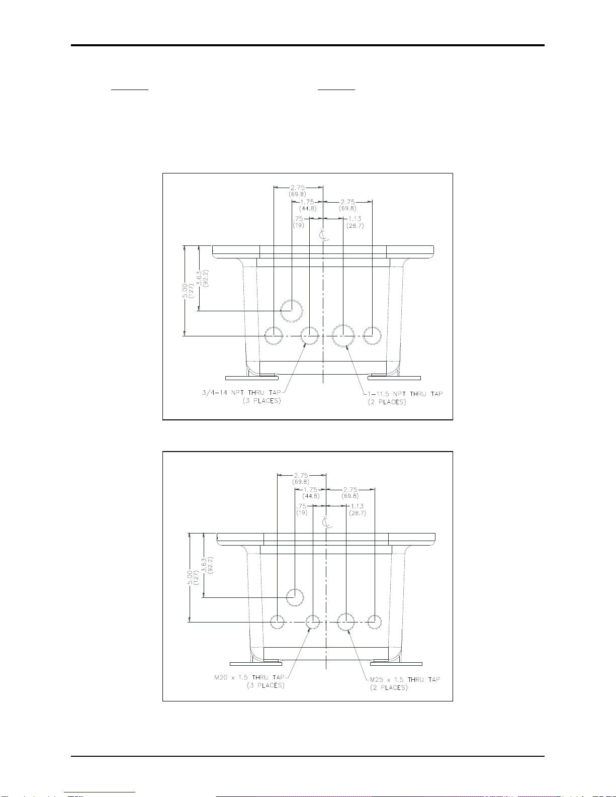
Cable Entries...........................................................................................................................................5
Opening the Station ................................................................................................................................6
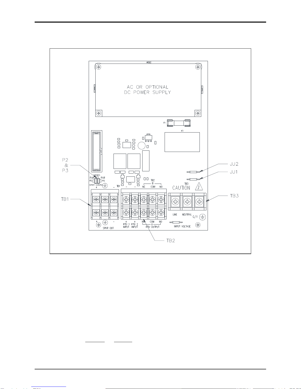
Field Wiring and Configuration............................................................................................................6
Station Ground......................................................................................................................................6
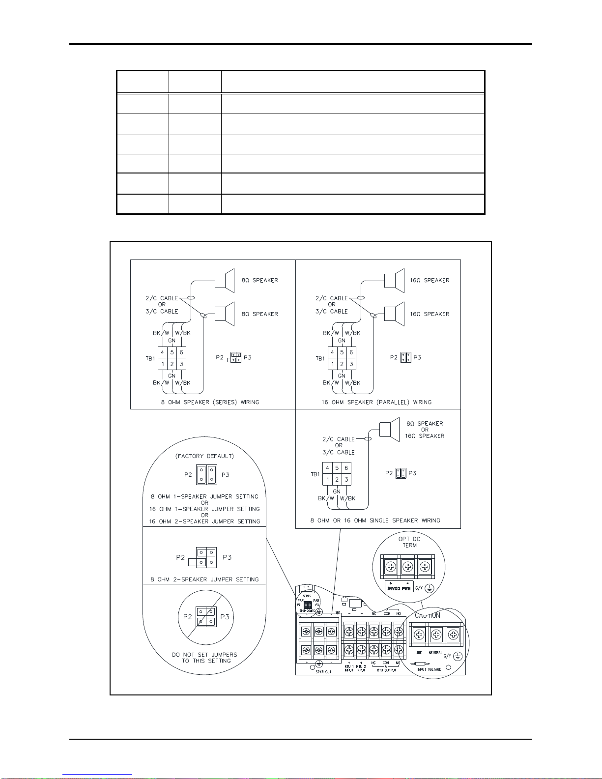
Termination PCBA Connections ..........................................................................................................7
Main PCBA—600-Ohm Audio I/O with Control...............................................................................11
Fiber Termination Board.....................................................................................................................12
Settings and Adjustments..............................................................................................................13
Opening the Station ..............................................................................................................................13
Main PCBA Configuration ..................................................................................................................14
Write Protect (EEPROM) Jumper.......................................................................................................14
WDOG Enable (Watchdog) Jumper ...................................................................................................14
Boot Enable Jumper............................................................................................................................ 14
Reset Switch........................................................................................................................................14
Speaker and 600-ohm Audio Output Volume..................................................................................... 15
Receiver Volume ................................................................................................................................15
Group and Station Number Selector Switches....................................................................................15
Main PCBA Indicators.........................................................................................................................16
Power LED..........................................................................................................................................16
Heartbeat LED....................................................................................................................................16
Ethernet Connection LEDs .................................................................................................................16
Five Configurable LEDs.....................................................................................................................16
Attaching the Front Cover...................................................................................................................16
Programming ................................................................................................................................16
Operation.......................................................................................................................................17