will vary from season to season on any
one setting of the temperature control, e.g.
if you have chosen 'Medium' power for
your preferred shower temperature in the
Summer, you may have to increase that
to 'Full' power during the Winter Months.
C. If for any reason there is a sudden rise
in water temperature, the Aqua 9000 XP
has thermal cut-out devices built-in.
D. Switch off immediately at the isolating
switch if water ceases to flow. Contact
Galaxy Customer Service for advice. If
ever the water becomes too hot and you
cannot obtain cooler water, first check that
the sprayplate in the sprayhead is not
blocked.
DO NOT place items such as soap or
Shampoo bottles on top of the unit. Liquid
could seep through the joint between the
cover and backplate, and possibly
damage the sealing rubber.
Replacement parts can be ordered from
Galaxy Customer Service..
Due to continuous improvement and
Updating, specification may be altered
Without prior notice.
5
SECTION
ELECTRICAL
REQUIREMENTS
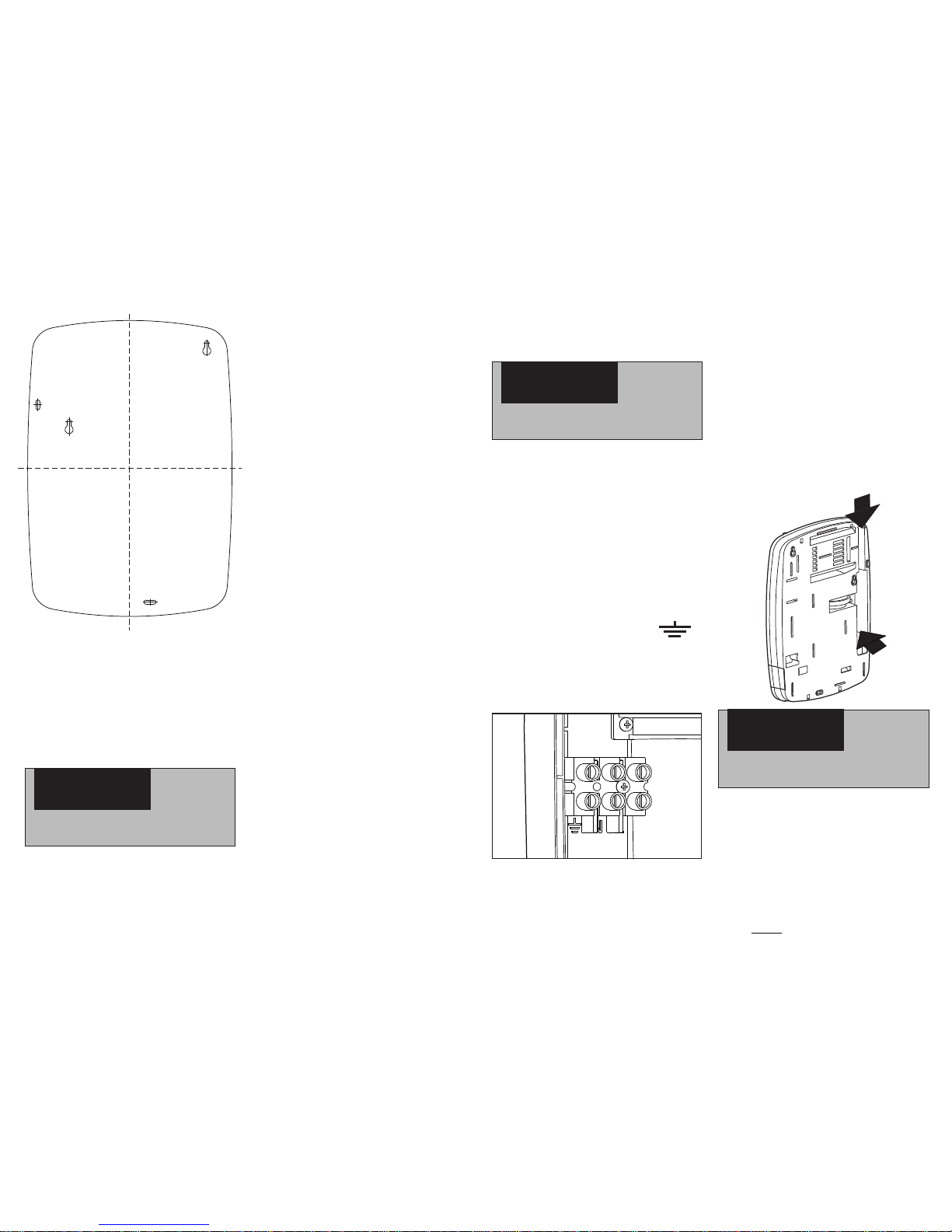
WARNING
THIS APPLIANCE MUST BE
EARTHED
The installation, supply cable and
circuit protection must conform with
IEE wiring regulations and be
sufficient for the amperage required.
2. If you are installing a shower with a
kilowatt rating above 9kW, it is
advisable to contact the local
electricity supply company.
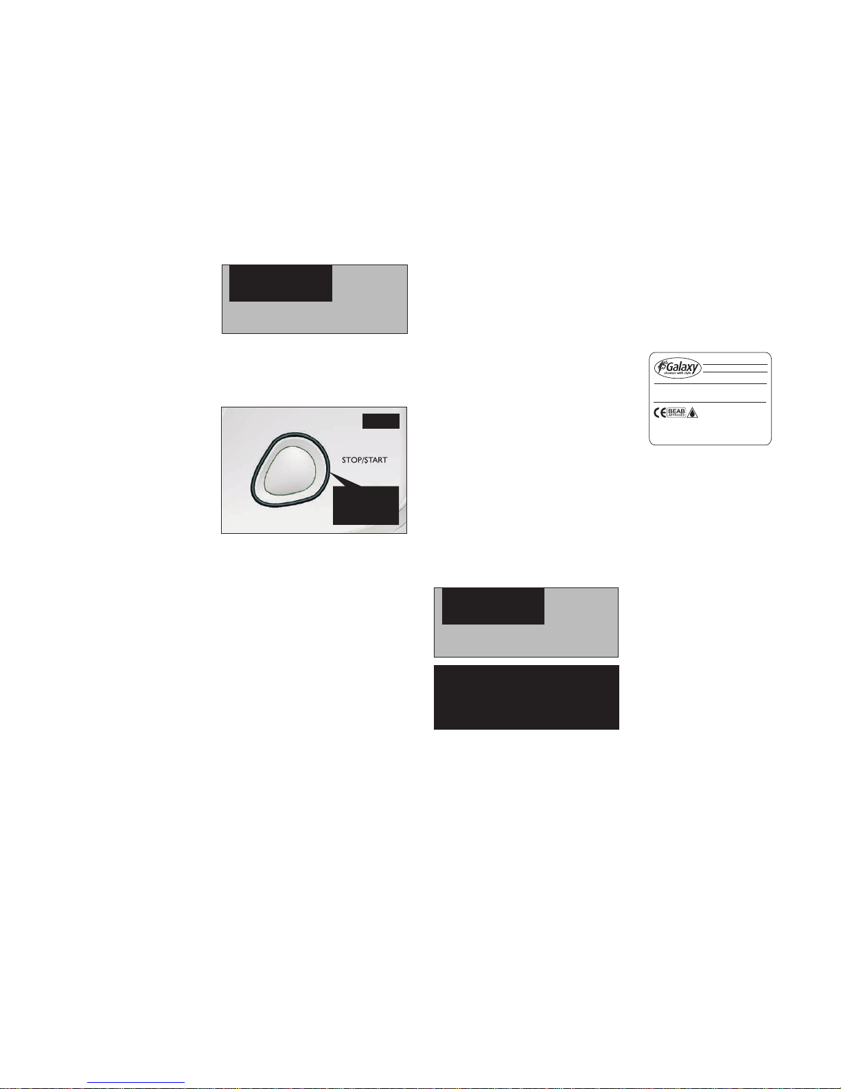
3. The electrical rating of the shower is
shown on the rating label (Fig.1)
within the unit.
4. Before making any sort of electrical
connection within the installation,
ensure that no terminal is live. If in
any doubt, switch off the whole
installation at the consumer unit.
5. The shower must be connected to its
own independent electrical circuit.
IT MUST NOT be connected to a ring
main, spur, socket outlet, lighting
circuit or cooker circuit.
6. The electrical supply must be
adequate for the loading of the unit
and existing circuits.
7. Check your consumer unit (main fuse
box) has a main switch rating of 80A
or above and that it has a spare fuse
way which will take the fuse or mcb
necessary for the shower.
8. If your consumer unit has a rating
below 80A or if there is no spare fuse
way, then the installation will not be
straight forward and may require a
New consumer unit serving the house
or just the shower.
9. You will need to contact the local
electricity company.They will check
the circuit and carry out what is
necessary. They will also check the
main bonding.
10. The earth continuity conductor of the
electrical installation must be
effectively connected electrically to all
exposed metal parts of other
MAX SUPPLY HEAD 10 METRES
MIN SUPPLY HEAD 0.08 METRES
RATING 20 MINS ON/60MINS OFF
RATED PRESSURE 0.Pa
THIS SHOWER UNIT WILL NOT
EXCEED A FLOW RATEOF 20 LPM
GALAXY SHOWERS
COVENTRY UK
REGISTERED DESIGN
Model: AQUA 9000XP
8.5KW 240V IPX4
SERIAL No: A9XP70005
1 2 3 4 5 6 7 8 9 10 11 12
The following notes are for guidance only:
1. The shower must only be connected
to a 230-240V ac supply.
Fig.1
‘High’ setting (Double Solid Red Symbol):
Is maximum power setting which
Allows the highest flow achievable
for your preferred temperature.
Temperature adjustment at this
setting is via the temperature
control.
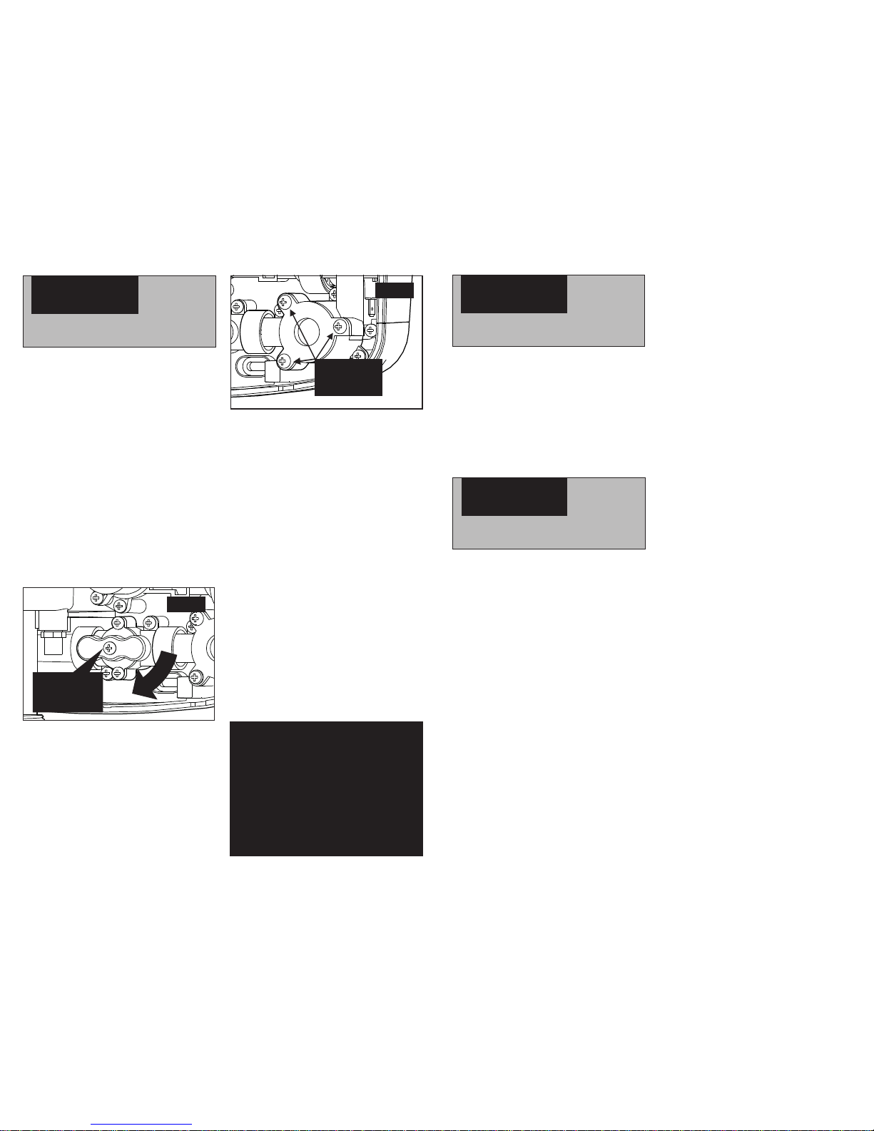
To adjust the shower temperature
The shower temperature is altered by
increasing or decreasing the flow rate of
the water through the shower via the
temperature control (Fig.19b).
After obtaining your preferred shower
temperature, the number can be
remembered as the normal setting and
should only need to be altered to
compensate for seasonal changes in
ambient water temperatures.
NOTE: To decrease the shower
temperature.
Turn the temperature control anti-
clockwise towards the
To increase the shower
temperature.
Turn the temperature control
clockwise towards the higher
numbers; this will decrease the
water flow.
CAUTION: Be certain the showering
temperature is satisfactory by testing
with your hand before stepping under
the sprayhead. There will always be a
time delay of ten to fifteen seconds
between selecting a flow rate and the
water reaching the stable temperature
for that flow rate.
It is recommended that persons who
may have difficulty understanding or
operating the shower controls should
not be left unattended whilst
showering. Special consideration
should be given to young children and
the less able bodied.
Power on indicator (Fig.20)
The Blue power neon will light when the
start/stop button is pressed. This indicates
that power is on to the pump and power
Selector.
15
SECTION
OPERATING FUNCTIONS
Low water pressure cut-out
Should the water pressure fall below the
minimum required to operate the shower,
power will be switched off to the heating
elements preventing any maintained
temperature rises.
Overheat cut-out
During normal operation if an overheat
temperature is sensed, power to the
elements will be reduced. Water will
continue to flow. When the temperature
has cooled sufficiently, power to
the elements will be automatically
restored to the previous setting at the time
of interruption.
Safety cut-out
The unit is fitted with a non re-settable
over-temperature safety device. In the
event of abnormal operation which could
cause unsafe temperatures within the unit,
the device will disconnect the heating
elements. It will require a visit from a
qualified engineer to determine the
nature of the fault and replace the safety
Fig.20
Blue Power
Neon