Galdera spas Geneva User manual

• GenevaTM • Niagara®• Tahitian®• Elation®• AspireTM
Utopia & Aquatic Melodies Serie
s
Owner’s Manua
l

OWNER’S MANUAL
This Owner’s Manual will acquaint you with the operation and general maintenance of your new spa. We suggest that you
take some time to carefully review all sections. Please keep this manual available for reference.
If you have any questions about any aspect of your spa’s set-up, operation or maintenance, contact your authorized Caldera
dealership. They are trained professionals who are familiar with the product as well as new spa ownership concerns. Their
expertise will facilitate the enjoyment of your new Caldera spa.
The serial number/identification label is located within the equipment compartment of your Caldera spa. The serial number
should also be documented on the delivery receipt from your dealer.
IMPORTANT: Watkins Manufacturing Corporation reserves the right to change specifications, or design, without notification
and without incurring any obligation.
DATE PURCHASED: ________________________________________
DATE INSTALLED: ____________________________________________
DEALER: __________________________________________________
ADDRESS: __________________________________________________
TELEPHONE: ________________________________________________
SPA MODEL/SERIAL NUMBER: ______________________________
COVER SERIAL NUMBER: ____________________________________
In most cities and counties, permits will be required for the installation of electrical circuits or the construction of exterior surfaces (decks and gazebos).
In addition, some communities have adopted residential barrier codes which may require fencing and/or self-closing gates on the property to prevent
unsupervised access to a pool (or spa) by children under 5 years of age. Your Caldera spa is equipped with a locking cover that meets the ASTM
F1346-91 Standard for Safety Covers, and as a result, is usually exempt from most barrier requirements. As a general practice, your local Building
Department will inform you of any applicable barrier requirements at the time a permit is obtained for the installation of an electrical circuit. Your Caldera
dealer can provide information on which permits may be required.
WELCOME
Watkins®Manufacturing Corporation congratulates you on your decision to enjoy the finest spa
available... Welcome to the growing family of Caldera®spa owners.
NOTE: This is an example. Your spa’s
label will contain different information.
Peel off top sticker and place here.
MODEL: Geneva
SERIES: UTOPIA
SERIAL: GEB 1G1022
RATINGS: 230V, 60HZ, 30A
GEB 1G1022
GEB 1G1022
GEB 1G1022
GEB 1G1022
GEB 1G1022

SAFETY INSTRUCTIONS
• Important Safety Instructions ......................................................................
1
• Important Spa Instructions ..........................................................................
3
INSTALLATION
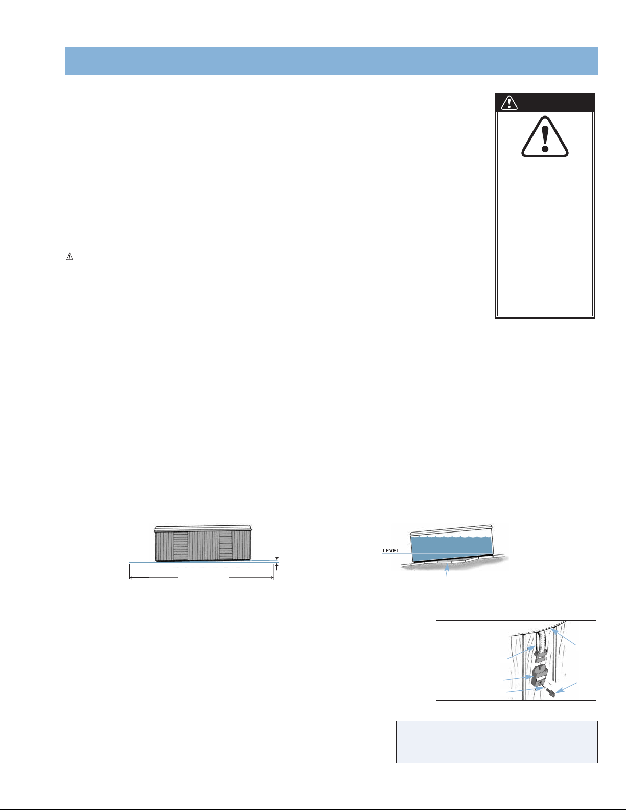
• Site Preparation............................................................................................
3
• Outdoor and Patio Installation ....................................................................
3
• Deck Installation ..........................................................................................
4
• Indoor/Basement Installation ......................................................................
4
• Spa Leveling Preparation ............................................................................
4
• Spa Cover Installation..................................................................................
4
CONTROLS AND EQUIPMENT
•Utopia GenevaTM ............................................................................................5
• Utopia Niagara®............................................................................................6
• Utopia Tahitian®............................................................................................7
• Aquatic Melodies®Elation®........................................................................8
• Aquatic Melodies®Aspire TM ........................................................................9
ELECTRICAL INSTALLATION
• Electrical Requirements and Precautions ................................................10
• 230 Volt Permanently Connected ............................................................10
START-UP AND REFILL PROCEDURES....12
CUSTOMIZING YOUR MASSAGE
• Diverter Valves ..........................................................................................
13
• AcquarellaTM Waterfall Valve......................................................................
13
• Atlas®Neck Jet Valve ..............................................................................
13
• Air Controls................................................................................................
13
• Hydro Jets ................................................................................................
13
• Air Jets ......................................................................................................
14
JET MENU
• Utopia Geneva Jet Menu ........................................................................
15
• Utopia Niagara Jet Menu ..........................................................................16
• Utopia Tahitian Jet Menu ..........................................................................17
• Aquatic Melodies Elation Jet Menu..........................................................18
• Aquatic Melodies Aspire Jet Menu ..........................................................19
OPERATING INSTRUCTIONS
• Control Panels ..........................................................................................
20
• Locking Features ......................................................................................
20
• Main Control Panel Buttons and Display ................................................
21
• Auxiliary Control Panel Buttons ................................................................22
• Aquatic Melodies®Surround Sound System ..........................................23
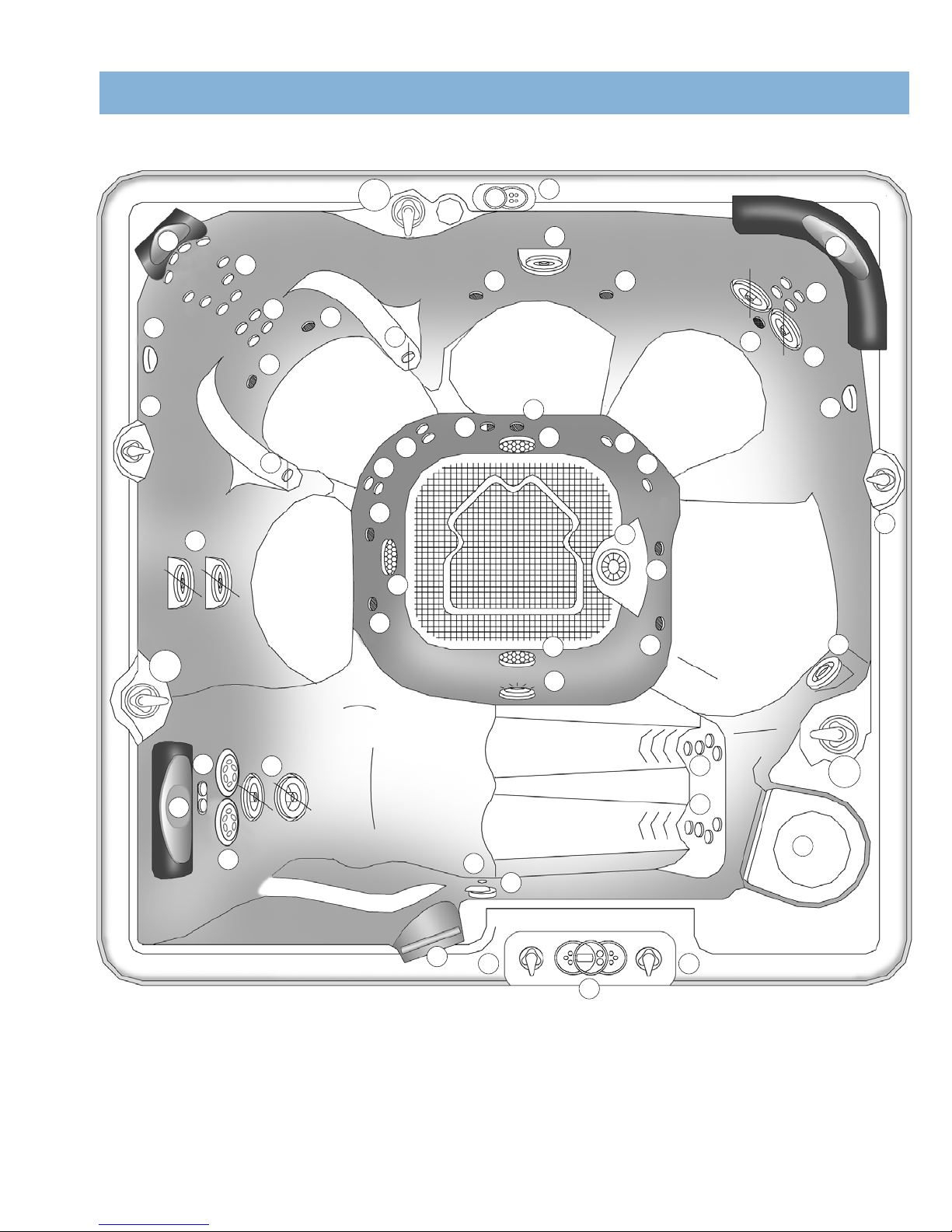
EQUIPMENT COMPARTMENTS
• Jet Pump Side ..........................................................................................24
• Controls Side ............................................................................................25
MAINTENANCE
• Filter Lid Removal and Replacement ......................................................
26
• Filter Maintenance ....................................................................................
26
• Filter Cartridge Removal and Cleaning Instructions ..............................
26
• Diverter Valve Maintenance......................................................................
26
• VersaSsage®Jets Maintenance ..............................................................
26
• Draining Your Spa ....................................................................................
27
• Winterizing Your Spa ................................................................................
27
• Care of the Spa Pillows ............................................................................
28
• Care of the Exterior ..................................................................................
28
• Care of the Spa Cover..............................................................................
28
WATER QUALITY AND MAINTENANCE
• General Information ..................................................................................
29
• Methods for Testing the Spa Water ........................................................
29
• The Watkins®Spa Water Maintenance Program....................................
30
• Chlorine (Sodium Dichlor) ........................................................................
32
• Monarch®Ozone System ........................................................................
34
• Common Water Chemistry Questions ....................................................
35
• Water Terminology ....................................................................................
35
• Spa Water Maintenance Troubleshooting Guide ....................................
36
SERVICE
• Miscellaneous Service Information ..........................................................
37
• Acts Invalidating Warranty........................................................................
37
• Disclaimers ................................................................................................
37
• Watkins Customer Service ......................................................................
37
SPA TROUBLESHOOTING ......................................38
SPA SPECIFICATION ................................Back Cover
TABLE OF CONTENTS

1
IMPORTANT SAFETY INSTRUCTIONS
READ AND FOLLOW ALL INSTRUCTIONS
AVOIDING THE RISK TO CHILDREN
DANGER:
•RISK OF CHILD DROWNING. Extreme caution must be exercised to prevent unauthorized access by children. To avoid accidents, ensure that children cannot
use a spa unless they are supervised at all times.
WARNING:
• To reduce the risk of injury, do not permit children to use this spa unless they are closely supervised at all times.
• To reduce the risk of injury, lower water temperatures are recommended for young children. Children are especially sensitive to hot water.
DO:
• Make sure you always lock the child resistant locks after using the spa for your children’s safety. Every Caldera®spa is equipped with a locking cover that meets
the ASTM F1346-91 Standard for Safety Covers.
• Test the water temperature with your hand before allowing children to enter the spa to be sure that it’s comfortable. Children are especially sensitive to hot water.
• Remind children that wet surfaces can be very slippery. Make sure that children are careful when entering, or exiting the spa.
DON’T:
• Allow children to climb onto the spa cover.
• Allow children to have unsupervised access to the spa.
AVOIDING THE RISK OF ELECTROCUTION
Risk of electrocution
• Connect only to a grounded source.
• Do not bury the power cord. A buried power cord may result in death, or serious personal injury due to electrocution if direct burial-type cable is not used, or if
improper digging occurs.
• A ground terminal (pressure wire connector) is provided on the control box inside the unit to permit connection of a minimum No. 10 AWG solid copper bonding
conductor between this point and any metal equipment, metal water pipe, metal enclosures of electrical equipment, or conduit within five feet (1.5 m) of the unit
as needed to comply with local requirements.
WARNING:
• To reduce the risk of electrical shock, replace a damaged cord immediately. Failure to do so may result in death or serious personal injury due to electrocution.
• Your spa is provided with a Ground Fault Circuit Interrupter for user and equipment protection. To ensure proper operation of this important safety device, test
according to the following instructions per electrical configuration.
230 volt, permanently installed models:
• A ground terminal is provided on the terminal block located inside the control box. To reduce the risk of electric shock, connect this terminal to the grounding
terminal of your electrical service or supply panel with a continuous green, insulated copper wire. The wire must be equivalent in size to the circuit conductors
supplying the equipment. In addition, a bonding terminal (pressure wire connector) is provided on the outside of the control box for bonding to local ground
points. To reduce the risk of electric shock, this connector should be bonded with a No. 10 AWG solid copper wire to any metal ladders, water pipes, or other
metal within 5 feet (1.5 m) of the spa to comply with local requirements. The means of disconnection must be readily accessible, but must be installed at least 5
feet (1.5 m) from the spa.
• Your spa is provided with a suitably rated circuit breaker to open all ungrounded supply conductors.
• Your spa uses ground fault circuit interrupters in the electrical subpanel. Before each use of the spa and with the unit operating, push the TEST button on each
breaker. The switch should click over to the “Trip” position. Wait 30 seconds and reset each GFCI breaker by switching it completely off and then completely on.
The switch should then stay on. If either of the interrupters does not perform in this manner, it is an indication of an electrical malfunction and the possibility of
an electric shock. Disconnect the power until the fault has been identified and corrected.
DANGER: RISK OF ELECTRICAL SHOCK
• Install spa at least 5 feet (1.5 m) from all metal surfaces. A spa may be installed within 5 feet of a metal surface if each metal surface is permanently connected
by a minimum No. 10 AWG solid copper conductor attached to the wire ground connector on the terminal box that is provided for this purpose if in accordance
with National Electrical Code ANSI/NMFPA70-1993.
• Do not permit any electrical appliances, such as a light, telephone, radio, or television within 5 feet (1.5 m) of a spa. Failure to maintain a safe distance may
result in death, or serious personal injury due to electrocution, if the appliance should fall into the spa.
• Install your spa is such a way that drainage is away from the electrical compartment and from all electrical components.
SAFETY INSTRUCTIONS

2
DO:
• Be sure your spa is connected to the power supply correctly - use a licensed electrical contractor.
• Disconnect the spa from the power supply before draining the spa or servicing the electrical components.
• Test the Ground Fault Circuit Interrupter(s) before each use.
DON’T:
• Use the spa with the equipment compartment door removed.
• Place electrical appliances within 5 feet (1.5m) of the spa.
• Attempt to open the electrical control box. There are no user serviceable parts inside.
RISKS TO AVOID
DANGER: RISK OF INJURY
• To reduce the risk of injury to persons, DO NOT remove floating weir, basket and filter located in the filter compartment while the spa is running.
• Never replace a suction fitting with one rated less than the flow rate marked on the original suction fitting.
• There is a danger of slipping and falling. Remember that wet surfaces can be very slippery. Take care when entering or exiting the spa.
• Never operate spa if the suction fittings are broken or missing.
• People with infectious diseases should not use the spa.
• Keep any loose articles of clothing or hanging jewelry away from rotating jets or other moving components.
Increased side effects of medication
• The use of drugs, alcohol or medication before or during spa use may lead to unconsciousness with the possibility of drowning.
• Persons using medications should consult a physician before using a spa; some medication may cause a user to become drowsy, while other medication may
affect heart rate, blood pressure, and circulation.
• Persons taking medications which induce drowsiness, such as tranquilizers, antihistamines, or anticoagulants should not use the spa.
Health problems affected by spa use
• Pregnant women should consult a physician before using spa.
• Persons suffering from obesity, or with a medical history of heart disease, low or high blood pressure, circulatory system problems, or diabetes should consult a
physician before using spa.
Unclean water
• Keep the water clean and sanitized with correct chemical care. The recommended levels for your Caldera®spa are:
Free Available Chlorine (FAC): 3.0-5.0 ppm
Water pH: 7.4-7.6
Total Alkalinity: 125-150 ppm
Calcium Hardness: 150-200 ppm
(Refer to Water Quality and Maintenance section for complete instructions.)
IMPORTANT: Turn on the clean cycle when adding ANY spa water chemicals into or in front of the filter compartment.
• Clean the filter cartridge at least monthly to remove debris and mineral buildup which may affect the performance of the hydromassage jets, limit the flow, or trip
the high limit thermostat, which will turn off the entire spa.
AVOIDING THE RISK OF HYPERTHERMIA
Prolonged immersion in hot water can result in HYPERTHERMIA, a dangerous condition which occurs when the internal temperature of the body reaches a level above
normal (98.6°F). The symptoms of hyperthermia include unawareness of impending hazard, failure to perceive heat, failure to recognize the need to exit the spa, physical
inability to exit the spa, fetal damage in pregnant women, and unconsciousness resulting in a danger of drowning.
WARNING:
The use of alcohol, drugs, or medication can greatly increase the risk of fatal hyperthermia in hot tubs and spas.
TO REDUCE THE RISK OF INJURY:
• The water in the spa should never exceed 104°F. Water temperatures between 100°F and 104°F are considered safe for a healthy adult. Lower water
temperatures are recommended for extended use (exceeding ten minutes) and for young children. Extended use can cause hyperthermia.
• Pregnant or possibly pregnant women should limit spa water temperatures to 100°F. Failure to do so may result in permanent injury to your baby.
• Do not use spa immediately following strenuous exercise.
AVOIDING THE RISK OF SKIN BURNS:
SAFETY INSTRUCTIONS

3
• To reduce the risk of injury, before entering a spa the user should measure the water temperature with an accurate thermometer, since the tolerance of
temperature-regulating devices may vary by as much as ±5°F.
• Test the water with your hand before entering the spa to be sure it’s comfortable.
SAFETY SIGN
Each Caldera®spa is shipped with a SAFETY SIGN in the owner’s package. The sign, which is required as a condition of Product Listing, should be permanently
installed where it is visible to the users of the spa. To obtain additional SAFETY SIGNS, contact your Caldera dealer and request Part #003021.
IMPORTANT SPA INSTRUCTIONS
The following contains important spa information, and we strongly encourage you to read and apply them.
DO:
• Use and lock the cover when the spa is not in use, whether it is empty or full.
• Follow the Spa Care and Maintenance recommendations stated in this manual.
• Use only approved accessories and recommended spa chemicals and cleaners.
DON’T:
• Leave the Caldera spa exposed to the sun without water or the cover in place. Exposure to direct sunlight can cause solar distress of the shell material.
• Roll or slide the spa on its side. This will damage the siding.
• Lift or drag the vinyl cover by using the cover lock straps; always lift or carry the cover by using the handles.
• Attempt to open the electrical control box. There are no user serviceable parts inside. Opening of the control box by the spa owner will void the warranty. If you
have an operational problem, carefully go through the steps outlined in the Troubleshooting section. If you are not able to resolve the problem, contact your
authorized Caldera dealer. Many problems can easily be diagnosed over the telephone by an Authorized Service Technician.
SAVE THESE INSTRUCTIONS
SITE PREPARATION
You probably have a spot picked out for your new spa, whether it’s indoors or outdoors, on a patio or on a deck.
Just make sure you check the following:
• Always put your spa on a structurally sound, level surface. A filled spa can weigh a great deal. Make certain that the location you choose can support the weight
of your filled spa.
• Don’t forget to level your spa before filling it. (See the Spa Leveling Preparation section of this manual.)
• Locate your equipment compartment, which houses all of the electrical components, in a place where water will drain away from it. Allowing water into the
equipment compartment can damage the electronics, or may result in tripping your house’s circuit breaker.
• Leave yourself easy access to the circuit breakers in the subpanel.
• Never let water get into the subpanel. Your 230 volt spa’s subpanel is rain-tight when installed correctly with the door closed. Periodically check these
conditions and correct any flaws if detected.
• Leave access to the equipment compartment for periodic spa care and maintenance.
WARNING: Damage to the spa’s equipment compartment components or internal plumbing as a result of rodent infestation is NOT covered under your
warranty!
OUTDOOR AND PATIO INSTALLATION
No matter where you install your new spa, it’s important that you have a solid foundation to support it. Structural damage to the spa, resulting from incorrect installation,
or placement on an inadequate foundation, is not covered under the spa’s limited warranty.
If you install the spa outdoors, we recommend a reinforced concrete pad at least four inches thick. The reinforcing rod or mesh in the pad should be attached to a bond wire.
DECK INSTALLATION
SAFETY INSTRUCTIONS
INSTALLATION

4
To be certain your deck can support your spa, you must know the deck’s maximum load capacity. Consult a qualified building
contractor or structural engineer. To find the weight of your spa, its contents and occupants, refer to the Spa Specification chart on
back page. This weight per square foot must not exceed the structure’s rated capacity, or serious structural damage could result.
INDOOR/BASEMENT INSTALLATION
Be aware of some special requirements if you place your spa indoors. Water will accumulate around the spa, so flooring materials
must provide a good grip when wet. Proper drainage is essential to prevent a build-up of water around the spa. When building a new
room for the spa it is recommended that a floor drain be installed. The humidity will naturally increase with the spa indoors. Water may
get into woodwork and produce dry rot, mildew, or other problems. Check for airborne moisture’s effects on exposed wood, paper,
etc. in the room. To minimize these effects, it is best to provide plenty of ventilation to the spa area. An architect can help to determine
if more ventilation must be installed.
Caldera spas are equipped with a jet pump shroud to remove excessive heat from the equipment compartment. Find this vent and be
sure the vent is not blocked by anything, including carpeting.
Your Caldera dealer can help you with local information such as zoning regulations and building codes.
WARNING: Please keep the area around your spa well ventilated when it is installed indoors or in a confined area. Inadequate
ventilation around the spa could cause a build-up of a higher-than-normal concentration of spa chemicals and/or bacterial fragments.
These dispersed spa chemicals and/or bacterial fragments can be inhaled, and may result in breathing difficulties or lung damage in
certain people suffering from a compromised immune system or respiratory infection. If you or other bathers are affected by this
condition, please seek medical attention as soon as possible.
In addition to the above, properly clean and maintain your spa as follows:
• Follow all procedures in this owner’s manual and printed instructions on all water care (chemical) products packaging.
• Test the water regularly to ensure proper levels of sanitizers, pH, and other water care requirements.
• Drain, clean, and refill your spa with fresh water on a regular schedule, and in accordance with this owner’s manual.
• Clean the filter at least once per month.
• Check to make sure you have proper circulation throughout your spa water system.
• Have spa users bathe before entering the spa water.
SPA LEVELING PREPARATION
Concrete sloped at 1 inch per 10 feet is preferred so that rain water and water spillover will run off and not puddle underneath the spa (water under the spa for long
periods of time may cause the wood to deteriorate). Other options are brick, stepping stone, or blocks.
It is important to note that soft surfaces, even when stepping stones are used to evenly distribute the weight of the spa, will have a tendency to settle, thus resulting in
an unleveled spa.
NOTE: Placing the spa on grass or dirt may increase the amount of debris which is inadvertently brought into the spa water and may cause harm to your equipment as
well as the spa surface, which is not covered under warranty.
SPA COVER
INSTALLATION
• Place the cover squarely on the spa.
• Position the tie-down locks included with your cover on the side of the spa so that they are easily reached by
the cover tie-down straps. Allow for about 1/2” to 3/4” slack in the straps to make it easy to insert straps into
locks and to compensate for vinyl shrinkage in cold weather.
• Attach the locks with the screws provided and insert the cover tie-down straps into the locks.
NOTE: Keeping the cover in place any time the spa is not in use will reduce the amount of time the heater operates,
thereby minimizing operating costs.
INSTALLATION
Slope 1 inch per 10 ft. for proper drainage.
Stepping stones or brick may settle
causing the spa to be unlevel.
COVER INSTALLATION
TIE-DOWN STRAP
LOCK
COVER
KEY
SCREW (2)
DANGER. RISK OF INJURY.
• Never leave a spa uncovered or unattended.
• Never leave a spa cover unlocked.
• Do not stand, sit, or lie on the cover.
WARNING
Watkins Manufacturing
Corporation recommends
that the Caldera®spa be
installed above ground.
Lowering the top of the spa
to ground level, or
employing decking which
raises standing level toward
the top of the spa
substantially increases the
hazard of accidental entry.
Consult a licensed building
contractor to design or
evaluate your custom
decking requirements.
1 inch
(2.5 cm)
10 ft. (305 cm)

OVERHEAD VIEW
5
CONTROLS AND EQUIPMENT
1. Air Control
2. Euro-Pulse
®
Jet
3. Euro Directional Jet
4. Air Jet
5. Magna
TM
Jet
6. MagnaSsage
TM
Jet
7. VersaSsage
®
Jet
8. OrbiSsage
TM
Jet
9. Whirlpool Jet
10. Euphoria
®
Jet
11. Diverter Valve
12. Suction Screen
13. Light
14. Ozone Jet
15. Control Panel
16. Pillow
17. Filter Compartment
18. Auxiliary Panel
19. Grab Rail
20. Atlas
®
Neck Jet Valve
21. Atlas Neck Jet Pillow
22. Temperature Sensor
23. Acquarella
TM
Waterfall Valve
1
11
1
3
3
4
4
4
4
4
6
5
7
7
9
11-1 18
11
11
12
13
14
15
22
16
19
16
21
20
17
1
2
2
3
3
4
4
4
4
8
3
3
3
33
3
4
UTOPIA GENEVATM
11-2
11-3
10
23

6
20
19
17
15
15
15
18
15
16
14
11
11
12
13 1
11
1
9
1 1
2
2
3
3
3
3
3
3
3
3
4
4
4
44
4
6
6
6
5
8
CONTROLS AND EQUIPMENT
1. Air Control
2. Euro-Pulse
®
Jet
3. Euro Directional Jet
4. Air Jet
5. Magna
TM
Jet
6. VersaSsage
®
Jet
7. OrbiSsage
TM
Jet
8. Whirlpool Jet
9. Euphoria
®
Jet
10. Diverter Valve
11. Suction Screen
12. Light
13. Ozone Jet
14. Control Panel
15. Pillow
16. Filter Compartment
17. Auxiliary Panel
18. Grab Rail
19. Atlas
®
Neck Jet Valve
20. Atlas Neck Jet Pillo
w
21. Temperature Senso
r
22. Acquarella
TM
Waterf
a
Valve
OVERHEAD VIEW
UTOPIA NIAGARA®
10-1
10-2
10-3
21
7
22

7
CONTROLS AND EQUIPMENT
1. Air Control
2. Temperature Sensor
3. Euro Directional Jet
4. Air Jet
5. MagnaSsage
TM
Jet
6. Magna
TM
Jet
7. VersaSsage
®
Jet
8. OrbiSsage
TM
Jet
9. Whirlpool Jet
10. Euphoria
®
Jet
11. Diverter Valve
12. Suction Screen
13. Light
14. Ozone Jet
15. Control Panel
16. Pillow
17. Filter Compartment
18. Auxiliary Panel
19. Grab Rail
20. Acquarella
TM
Waterfall Valve
1
1 1
3
3
33
3
4
4
4
4
4
5
6
7
7
9
10
12
12
12
13
15
19
16
16
16
18
17
1
3
3
4
4
4
3
3
OVERHEAD VIEW
UTOPIA TAHITIAN®
14
1
11-1
11-2
11-3
2
8
20

8
CONTROLS AND EQUIPMENT
1. Air Control
2. Temperature Sensor
3. Euro Directional Jet
4. Euro-Pulse
®
Jet
5. MagnaSsage
TM
Jet
6. Magna
TM
Jet
7. VersaSsage
®
Jet
8. OrbiSsage
TM
Jet
9. Euphoria
®
Jet
10. Ozone Jet
11. Diverter Valve
12. Suction Screen
13. Light
14. Pop-up Speakers
15. Control Panel
16. Pillow
17. Filter Compartment
18. Grab Rail
19. Acquarella
TM
Waterfall
Valve
20. Auxiliary Control
Panel
21. Atlas NeckJet Valve
22. Atlas NeckJet Pillow
1
3
3
3
3
3
4
13
16
18
22
16
17
2
12
12
12
14
1
3
3
4
5
10
9
1
3
7
15 1
1
OVERHEAD VIEW
AQUATIC MELODIES®ELATION ®
11-1
11-2
6
7
14
14
16
8
19
20
21

9
CONTROLS AND EQUIPMENT
1. Air Control
2. Temperature Sensor
3. Euro Directional Jet
4. Euro-Pulse
®
Jet
5. Magna
TM
Jet
6. VersaSsage
®
Jet
7. OrbiSsage
TM
Jet
8. Euphoria
®
Jet
9. Ozone Jet
10. Diverter Valve
11. Suction Screen
12. Light
13. Pop-up Speakers
14. Control Panel
15. Pillow
16. Filter Compartment
17. Grab Rail
18. Acquarella
TM
Waterfall Valve
19. Auxiliary Control
Panel
OVERHEAD VIEW
AQUATIC MELODIES®ASPIRETM
1
1
1
1
1
2
3
3
3
3
3
3
3
4
4
5
6
6
6
7
8
9
10-1
10-2 11
11
11
12
13
13
13
14
15
15 15
15
16
17
18
1
19

10
ELECTRICAL INSTALLATION
ELECTRICAL REQUIREMENTS AND PRECAUTIONS
Your Caldera®spa has been carefully designed to give you maximum safety against electrical shock. Connecting the spa to an improperly wired circuit will negate many
of the spa’s safety features. Improper wiring may also cause electrocution, risk of fire, and other risks of injuries. Please read and follow the electrical installation
requirements and instructions for your spa completely!
230 VOLT PERMANENTLY CONNECTED
CALDERA SPAS MUST BE WIRED IN ACCORDANCE WITH ALL APPLICABLE LOCAL ELECTRICAL CODES. ALL ELECTRICAL WORK SHOULD BE DONE BY AN
EXPERIENCED LICENSED ELECTRICIAN. WE RECOMMEND THE USE OF APPROPRIATE ELECTRICAL CONDUIT, FITTINGS, AND WIRE FOR ALL CIRCUITS.
An electrical subpanel containing two GFCI breakers is included with each spa. We recommend that this subpanel be used to supply power and protect the spa.
This subpanel requires a 50 amp, single phase, 230 volt, four wire service (two line, one neutral, one ground). The ground wire must never be less than #10 AWG. Use
NEC 250-122 (table) and local codes for more information. A minimum #10 AWG solid copper bond wire is also required.
Mount the subpanel in the vicinity of the spa, but not within five feet, in accordance with local codes.
INSTALLATION INSTRUCTIONS
1. To connect the electrical service, first remove the screws from the equipment compartment door (remove the fiber optic light cover and remove fiber optic cable
from door), lower the door one inch and remove the door.
2. Locate the spa control box. Remove the screws on the front of the control box and remove the control box cover.
3. Route the electrical service from the subpanel into the spa equipment compartment.
NOTE: The subpanel must be placed in sight of the spa, no closer than five feet.
4. Connect wire to bottom of control box using a minimum of ₃/₄” liquid-tight, flex conduit fitting.
WIRING CONNECTIONS
1. Identify the TB-1 terminal block, located inside the control box at the lower left-hand corner.
2. Connect the #12 AWG, BLUE wire, from the subpanel 20 amp breaker, terminal L1 to TB-1, terminal 1
3. Connect the #12 AWG, RED wire, from the subpanel 20 amp breaker, terminal L2 to TB-1, terminal 3
NOTE: The WHITE neutral wire must be attached to the LOAD neutral on the 230 volt, 30 amp breaker (not to the neutral bus bar in the subpanel). The WHITE neutral
wire coming from the breaker itself is already connected to the neutral bus bar.
4. Connect the #10 AWG, BLUE wire, from the subpanel 30 amp breaker, terminal L1 to TB-1, terminal 2
5. Connect the #10 AWG, RED wire, from the subpanel 30 amp breaker, terminal L2 to TB-1, terminal 4
6. Connect the #10 AWG, WHITE wire, from the subpanel 30 amp breaker, terminal N (load neutral) to TB-1, terminal 5
7. Connect the #10 AWG, GREEN wire, from the subpanel GROUND bar to TB-1, system ground terminal.
8. Using the pressure wire connector provided on the outside of the control box, bond the spa to all exposed metal equipment or fixtures, handrails, and the concrete
pad (if applicable) per N.E.C. and local codes.
9. Replace the control box cover and securely tighten the fastening screws. Close and secure the equipment compartment door as follows:
• Place top of door or panel directly below bartop against the frame of the spa.
• Push bottom of door or panel against the spa frame.
• Slide door or panel upward (pushing in on center of door) until screw holes line up.
• Slightly pull on door or panel, if door remains against the spa then replace the screws.
• If the door does not lock into position, repeat the previous steps.
WARNING: FILL THE SPA WITH WATER BEFORE TURNING ON THE POWER! (See STARTUP AND REFILL PROCEDURES).
Once your spa has been filled with water, turn it on and test all of the circuit breakers.
NOTE: If both breakers immediately trip, verify that the #10 AWG WHITE neutral wire is connected from TB-1 terminal 5 to the N (load neutral) terminal of the 30 amp
subpanel breaker. Each breaker should be tested prior to each use. Here’s how:
1. Push the “TEST” button on each GFCI breaker, and observe it click OFF.
2. Wait 30 seconds, then push the breaker switch to the OFF (down) position (to ensure that it has completely disengaged), then push the breaker switch to the ON
(up) position. If you don't wait 30 seconds, the spa’s control panel may flash four lines on and off – try again.
If any of the GFCI breakers fails to operate in this manner, your spa may have an electrical malfunction, and you may be at risk of electrical shock. Turn off all circuits
and do not use the spa until the problem has been corrected by an authorized service agent.
SERVICE NOTE: All Caldera spas have diagnostic functions that are displayed on the control panel. Four flashing lines are visible on the control panel if the heater high
limit thermostat has tripped. If the four flashing lines are visible, follow the instructions in the troubleshooting section to identify and correct the cause. The four flashing
lines will stop flashing once the problem has been corrected.

11
WARNING: Removing or bypassing any GFCI breaker will result in an unsafe spa and will void the spa’s warranty.
IMPORTANT: Should you ever find the need to move or relocate your Caldera®spa, it is essential that you understand and apply these installation requirements. Your
Caldera spa has been carefully engineered to provide maximum safety against electric shock. Remember, connecting the spa to an improperly wired circuit will negate
many of its safety features.
NOTE: Long wiring runs may require larger-gauge wire than stated.
ELECTRICAL INSTALLATION
System Ground Terminal
GRD
WARNING!
THE EXACT PHYSICAL LOCATION OF THE TERMINALS ON THE GFCI BREAKER
WILL VARY BETWEEN MANUFACTURERS. CONNECTING THE HOT WIRE TO THE
NEUTRAL TERMINAL WILL CAUSE IRREVERSIBLE DAMAGE TO THE CONTROL BOX.
** Refer to NEC 250-122 (table)
*PROVIDED WITH SPA. NOTE: ALL WIRING SHOULD BE COPPER.
230 Volt Permanently Connected
** Refer to NEC 250-122 (table)
NOTE: The wire connections to GFCI breakers are for reference only. Always ensure the white neutral wire is connected to the load neutral of the 30 amp breaker.
**
**
POWER CONNECTION ACCESS
230V WIRING ACCESS
OPENINGS ON RIGHT& LEFT
HAND SIDE
EQUIPMENT COMPARTMENT
DOOR
PUMP DOORS
CONTROL BOX
DRAIN VALVE

12
Your Caldera®spa has been thoroughly tested during the manufacturing process to ensure reliability and long-term customer satisfaction. A small amount of water may
have remained in the plumbing after testing and, as a result, may have spotted the spa shell or the spa siding prior to delivery. Before filling the spa, clear all debris from
the spa and wipe the spa shell clean with a soft rag.
THE FOLLOWING INSTRUCTIONS MUST BE READ AND FOLLOWED EXACTLY TO ENSURE A SUCCESSFUL START-UP OR REFILL.
CAUTIONS
• Do not fill the spa with hot water, as tripping of the high-limit thermostat may result.
• DO NOT CONNECT POWER TO AN EMPTY SPA. Power to the spa automatically activates critical components within the spa, such as controls,
heater, circulation pump and other systems. If power is supplied to these components prior to the spa being filled, the components will be damaged,
and this may result in a non-warranty component failure.
• Do not use your spa after filling until all of the steps listed below are completed.
• Do not add chlorine if treating your spa with polyhexamethylene biguanide (Biguanide, PHMB, eg. BaquaSpa™) sanitizer.
• Before filling your spa for the first time, remove the equipment compartment door and pump door (remove drain valve collar from pump door first)
and check to ensure that the unions on either side of the pump are hand-tight.
1. Close all drains and fill the spa with water by removing the filter lid, skimmer basket, weir and filter (see Filter Lid Removal instructions). Then insert the end of a
garden hose into the filter canister and begin filling the spa. The water level of your Caldera spa should be approximately one inch above the highest jet in the spa
excluding the four above-water-line neck jets in the EcstaSeatTM (GenevaTM , Niagara®and Elation®only). Reinstall the skimmer basket, weir, filter and filter lid once the spa
is filled.
IMPORTANT: Watkins®Manufacturing Corporation does not recommend that the spa be filled with “softened” water, as this may damage the spa’s equipment.
2. AFTER the spa has been filled with water and the equipment compartment door is secured, power must be applied to the spa.
• Activate power to the subpanel from the main house panel first.
• Open the door of the electrical subpanel and reset the GFCI breakers. Close and secure the subpanel door.
3. The jet pumps, heating system and all internal plumbing will achieve a partial prime as the spa is filled. Five minutes after power is applied to the spa, the air blower
will activate for one minute (Utopia series only), followed by Jet Pump 2 on high speed for one minute, followed by Jet Pump 1 for eight minutes (nine minutes for
Aquatic Melodies series). Once the jet system is fully operational (as indicated by strong, non-surging jets), priming of the spa is complete. If you do not feel a
steady stream of water from your jets, refer to the instructions for priming the pump in the SPA TROUBLESHOOTING section in the back of this manual.
4. Adjust Total Alkalinity (TA) to 125 ppm, Calcium Hardness (CH) to 150 ppm, then spa water pH to between 7.4 and 7.6. These procedures are listed in the “Water
Quality and Maintenance” section.
IMPORTANT: Add spa water chemicals directly into or in front of the filter compartment (do not remove filter lid) while the jet pump is on and run for at least ten
minutes (depress “CLEAN” button on the control panel).
OPERATION NOTE: Adjusting the Total Alkalinity as the first step is important, as out-of-balance TA will affect your ability to adjust the pH correctly and will prevent
the sanitizer from operating effectively.
5. Superchlorinate the spa water by adding 1-1/2 teaspoons of chlorine (sodium dichlor) per 250 gallons of spa water. When adding chlorine, the jet pump should be
running, and remain on to circulate the spa water for a ten-minute period (use clean cycle). Make sure all the diverter valves are set to the middle position.
6. Set the temperature control to the desired temperature (between 100°F and 104°F), then place the vinyl cover on the spa and allow the water temperature to
stabilize (approximately 24 hours). Make sure you secure the cover in place using the cover locks. Periodically check the spa water temperature. When the water
temperature climbs above 90°F, proceed to the next step.
7. Press “CLEAN” button on the main control panel, this will run jet pump one for ten minutes to circulate the spa water. Make sure all the diverter valves are set to the
middle position. Once the jets shut off, test the spa water for Free Available Chlorine (FAC) residual. If the residual is between 3 and 5 ppm, go on to the next step. If
the residual is less than 3 ppm, superchlorinate the spa water by adding 1-1/2 teaspoons of chlorine (sodium dichlor) per 250 gallons of spa water, while the jet
pump is running. Run the jet pump to circulate the spa water for an additional ten-minute period.
8. Recheck the Total Alkalinity (TA) at 125 ppm, Calcium Hardness (CH) at 150 ppm, then spa water pH at between 7.4 and 7.6.
OPERATION NOTE: Make sure you adjust your Total Alkalinity first, as an out-of-balance condition will affect your ability to adjust the pH correctly, and will prevent
the sanitizer from operating effectively. The spa is ready for use when the spa water has circulated and the chlorine level remains between 3 ppm and 5 ppm.
9. The spa temperature is pre-programmed to reach 102°F, and will normally do so within 18 to 24 hours. You may raise the water temperature by pressing the
“TEMP (▲)” button on the control panel once to display the temperature, then pressing it again within five seconds to raise the temperature, or lower it by pressing
“TEMP (▼)” button once to display the temperature, then pressing it again within five seconds to lower the temperature. After a few hours, the water temperature
will remain within 1-1/2 degrees of your selected temperature.
OPERATION NOTE: For proper water circulation during the automatic clean cycle the following steps should be performed.
• Place the diverters in the middle (split flow) position.
• Place air control levers in OFF position by rotating clockwise.
START-UP AND REFILL PROCEDURES

CUSTOMIZING YOUR MASSAGE
Your Caldera®spa offers numerous ways for you to customize your massage experience. Experimentation is the best way to find what feels best to you. Try sitting in
different seats, adjusting the diverter valves, air controls, and jet nozzles and turning each pump on or off.
DIVERTER VALVES
The diverter valves on your spa allow you to direct the flow of water from the pumps to
various combinations of jets. The functions of these diverter valves can best be learned
by experimentation as follows:
1. Set all air controls to the “ON” position by rotating counterclockwise.
2. Turn on both pumps.
3. Turn the handle on each diverter valve and see which groups of jets are affected.
(Note that you can adjust the diverter valves to any position between the two
possible extremes to achieve the jet pressure that feels best to you.)
IMPORTANT: Your spa is not designed to provide full power to all jets when the
diverter valves are in the “mid” position. However, with the diverter valve in this
position, you may increase the power to selected jets by rotating the face of the
MagnaTM and MagnaSsageTM jets to close the ones that are not in use.
TIP: Turn both pumps on and place the diverter valves to the “Mid-Position”. Then experiment with each of the air controls to see their effect.
ACQUARELLATM WATERFALL VALVE
Your spa is equipped with the Acquarella waterfall feature. It is activated by turning on jet pump 2 (either low or
high speed). The flow is regulated by turning the Acquarella waterfall valve on the inside wall of the spa.
ATLAS®NECK JET VALVE
The GenevaTM, Niagara®, and Elation®spas are equipped with 4 directional neck jets located in the EcstaSeatTM.
The flow of the neck jets is regulated by turning the Atlas NeckJet valve on the inside wall of the spa.
AIR CONTROLS
Each jet system has its own air control. These allow you to change the power of the jets by regulating the amount of
air that is mixed with the water coming out of the jets.
HYDRO JETS
Magna Jets - These jets allow you to redirect the jet stream by changing the position of the nozzle.
MagnaSsage Jets - These jets provide a rotating massage pattern.
The nozzles in the Magna jets and the MagnaSsage jets are interchangeable. To remove a MagnaSsage rotating
nozzle, simply grasp it and pull straight out. To install, align and push straight in, the nozzle will snap into place. To
remove, or install a standard Magna jet nozzle, rotate the tabs on either side of the nozzle. Additional MagnaSsage
rotating nozzles and dual-port nozzles are available from your Caldera dealer.
Both the Magna and MagnaSsage jets allow you to regulate the force of the massage. Rotate the fascia ring
clockwise to reduce the force, or counter-clockwise to increase the force. Notice that turning off the flow to some
jets increases the flow to the other jets. To avoid damage to your spa’s plumbing and components, do not turn off
more than half of these jets at the same time.
Position 1 - The full flow
is directed to one series
of jets.
Mid-Position -
Positioning the diverter
at any point between
position one and two
divides the flow between
the jet systems.
Position 2 - The full flow
is directed to a second
series of jets.
13
Magna Jet MagnaSsage Jet
OFF ON

14
CUSTOMIZING YOUR MASSAGE
Euro Directional and Euro-Pulse Jets - The Euro Directional jets, with eyeball nozzles, deliver a direct, more focused massage. The Euro-Pulse jets feature a special
insert that creates a soft, pulsating, rotary massage. The Euro-Pulse jet cap assemblies may be removed if you want a more powerful, direct massage in the wrist
locations. To do this, rotate counter clockwise and pull off. If you desire, you may install a Euro-Pulse jet cap removed from one jet onto a standard Euro Directional jet
by simply snapping the assembly into place. You may purchase additional roto jet assemblies from your Caldera®dealer.
VersaSsage Jets - These jets may be adjusted to provide either a stationary, direct stream, or, by positioning the nozzle to one side, a variety of rotating massage
patterns. Also, the speed of the rotation can be changed by rotating the jet faceplate from a full stream, to shutting the jet completely off. For cleaning or replacement
instructions see VersaSsage & OrbiSsage Jets Maintenance section. To avoid damage to your spa’s plumbing and components, do not turn off more than half of these
jets at the same time.
OrbiSsage Jets -This jet provides a unique, pulsating massage. The flow is adjustable in that it can be turned completely off or on (by rotating the jet faceplate). It is
also interchangeable with the VersaSsage jet. For cleaning or replacement instructions see VersaSsage & OrbiSsage Jets Maintenance section.
AIR JETS
The air jet system consists of a 1 HP air pump and 10 air jets found on GenevaTM, Niagara®, and Tahitian®
spas. At the beginning of the automatic operation cycle, the air jets will operate for one minute to clean out
the air channel. The air jets deliver air bubbles to provide subtle pulsation for a gentle, soft-tissue massage.
Euro Directional Jet Euro-Pulse
®
Jet
VersaSsage
®
Jet
Air Jet
OrbiSsage
™
Jet

Combination Jet System
15
JET MENU
Jet Pump 1–Jet System 1
Located in EcstaSeat™ – back left:
•
2 Euro-Pulse®jets
•
14 Euro Directional jets
•
4 directional neck jets
Jet Pump 1–Jet System 2
•
2 MagnaSsage™jets on left wall
•
1 Magna™jet on back wall
•
4 directional neck jets
Located in LumbarSsage® seat – back right:
•
6 Euro Directional jets
• 2 VersaSsage®jets
Jet Pump 2–Jet System 1
•
Acquarella
TM
Waterfall
Located in Ultra Massage lounge – front:
•
8 Sole Soothers®
•
2 Euro Directional jets
•
2 VersaSsage jets
•
2 OrbiSsage™jets
Jet Pump 2–
Jet System 2
Located in Ultra Massage
seat – front right:
•
2 Euro Directional jets
•
2 VersaSsage jets
•
2 OrbiSsage jets
(Activates right side diverter)
Right Side Jet System 1:
•
1 Whirlpool jet on right wall
•
Acquarella Waterfall
Jet Pump 2–
Jet System 2
Located in Ultra Massage
seat – front right:
•
2 Euro Directional jets
•
2 VersaSsage jets
•
2 OrbiSsage jets
(Activates right side diverter)
Right Side Jet System 2:
•
1 Euphoria®jet in footwell
•
Acquarella Waterfall
Jet Pump 1 diverter in mid position activates both Jet Pump 1 Systems 1 and 2.
Jet Pump 2 diverter in mid position activates both Jet Pump 2 Systems 1 and 2.
Right Side diverter in mid position activates Right Side Systems 1 and 2.
UTOPIA GENEVA
TM

16
JET MENU
Jet Pump 1–Jet System 1
Located in EcstaSeat™ – back left:
•
2 Euro-Pulse®jets
•
14 Euro Directional jets
•
4 directional neck jets
Jet Pump 1–Jet System 2
•
1 Magna™jet on right wall
•
2 VersaSsage®jets on front left wall
•
4 directional neck jets
Located in LumbarSsage® seat – back right:
•
6 Euro Directional jets
•
2 Versa jets
Jet Pump 2–Jet System 1
•
8 Sole Soothers®in back center
•
Acquarella
TM
Waterfall
Located in Ultra Massage seat – front right:
•
2 Euro Directional jets
•
2 VersaSsage jets
•
2 OrbiSsage™jets
Jet Pump 2–
Jet System 2
Located in Ultra Massage
seat – front right:
•
2 Euro Directional jets
•
2 VersaSsage jets
•
2 OrbiSsage jets
(Activates right side diverter)
Right Side Jet System 1:
•
1 Whirlpool jet on right wall
•
Acquarella Waterfall
Jet Pump 2–
Jet System 2
Located in Ultra Massage
seat – front right:
•
2 Euro Directional jets
•
2 VersaSsage jets
•
2 OrbiSsage jets
(Activates right side diverter)
Right Side Jet System 2:
•
1 Euphoria®jet in footwell
•
Acquarella Waterfall
Combination Jet System
Jet Pump 1 diverter in mid position activates both Jet Pump 1 Systems 1 and 2.
Jet Pump 2 diverter in mid position activates both Jet Pump 2 Systems 1 and 2.
Right Side diverter in mid position activates Right Side Systems 1 and 2.
UTOPIA NIAGARA
®

17
JET MENU
Jet Pump 1–Jet System 1
Located in EcstaSeat™– back left:
•
16 Euro Directional jets
Jet Pump 1–Jet System 2
•
2 MagnaSsage™jet on left wall
•
1 Magna™jet on back wall
Located in LumbarSsage® seat – back right:
•
6 Euro Directional jets
•
2 VersaSsage®jets
Jet Pump 2–Jet System 1
•
Acquarella
TM
Waterfall
Located in Ultra Massage seat – front:
•
8 Sole Soothers®
•
2 Euro Directional jets
•
2 VersaSsage jets
•
2 OrbiSsage™jets
Jet Pump 2–
Jet System 2
Located in Ultra Massage
seat – front right:
•
2 Euro Directional jets
•
2 VersaSsage jets
•
2 OrbiSsage jets
(Activates right side diverter)
Right Side Jet System 1:
•
1 Whirlpool jet on right wall
•
Acquarella Waterfall
Jet Pump 2–
Jet System 2
Located in Ultra Massage
seat – front right:
•
2 Euro Directional jets
•
2 VersaSsage jets
•
2 OrbiSsage jets
(Activates right side diverter)
Right Side Jet System 2:
•
1 Euphoria®jet in footwell
•
Acquarella Waterfall
Combination Jet System
Jet Pump 1 diverter in mid position activates both Jet Pump 1 Systems 1 and 2.
Jet Pump 2 diverter in mid position activates both Jet Pump 2 Systems 1 and 2.
Right Side diverter in mid position activates Right Side Systems 1 and 2.
UTOPIA TAHITIAN
®
This manual suits for next models
4
Table of contents
Popular Hot Tub manuals by other brands

Aquatic
Aquatic INFINITY 1 Specifications

Jacuzzi
Jacuzzi LUNA PLUS Specification sheet

Marquis
Marquis Vector21 Series owner's manual

Dimension One Spas
Dimension One Spas Dupree Bay Specifications

Aqua Pulse Spas
Aqua Pulse Spas Shelly Deluxe Spa user manual

Schmidlin
Schmidlin Schmidlin JET Instructions for use

Jacuzzi
Jacuzzi HE96000 Installation and operation instructions

AquaTerra
AquaTerra Montecito owner's manual

Jacuzzi
Jacuzzi BELLAVISTA 5.5 Specification sheet

Del ozone
Del ozone spa solar eclipse installation manual

Sterling Plumbing
Sterling Plumbing ENSEMBLE 76121120 Specifications

Wave
Wave Luxury M-1313 user guide