Gallagher 3E3260 User manual

Instructions
Installatie instucties
Notice d’installation
Betriebsanleitung
Instrucciones
Monteringsinstrucktioner
- ENG
- NED
- FRA
- DEU
- ESP
- SVE
FENCE VOLT / CURRENT METER &
FAULT FINDER

PUBLISHED BY
Gallagher Group Limited
181 Kahikatea Drive, Private Bag 3026
Hamilton, New Zealand
www.gallagher.co
Copyright© Gallagher Group Limited 2012
All rights reserved. Patents pending.
Gallagher Fault Finder User Manual
3E3260 - Edion 2- December 2013
DISCLAIMER: Whilst every effort has
been made to ensure accuracy, neither
Gallagher Group Limited nor any employee
of the company shall be liable on any
ground whatsoever to any party in respect
of decisions or acons they may make as a
result of using this informaon.
In accordance with the Gallagher policy
of connuing development, design and
specificaons are subject to change
without noce.
Developed and manufactured by Gallagher
Group Limited, and ISO 9001 2000
Cerfied Supplier.

Contents
English
Specificaons .........................................................................4
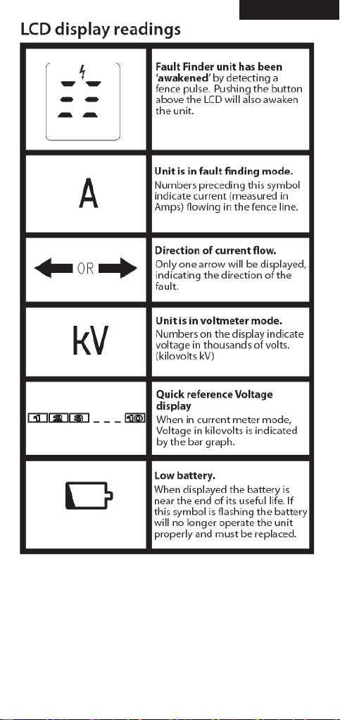
Volt Meter Mode....................................................................4
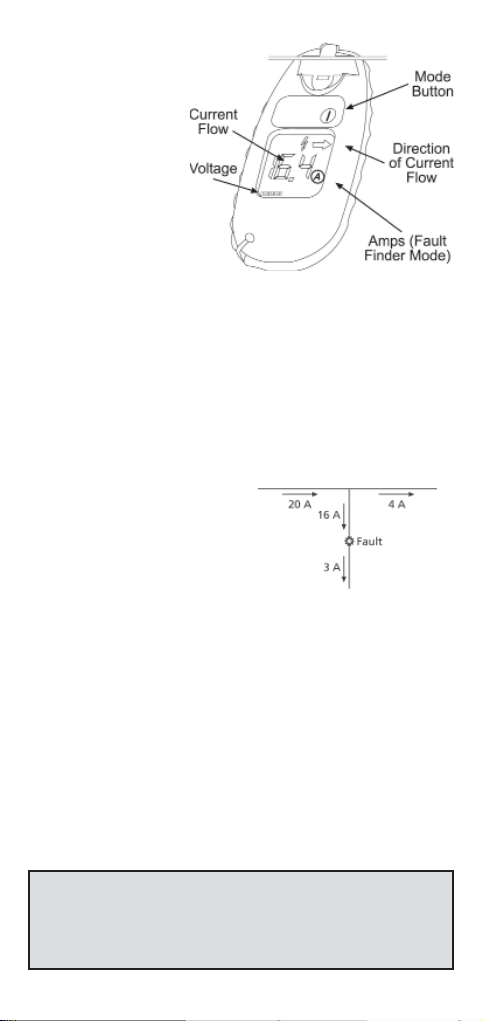
Fault Finder Mode..................................................................4
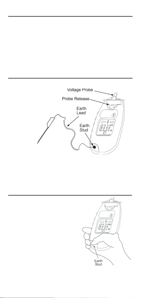
Voltage Probe.........................................................................6
Earth Lead Accessory .............................................................6
Replacing the Fault Finder Baery .........................................6
Understanding your Electric Fence ........................................7
Waste electrical and electronic equipment............................8
Nederlands
Specificaes: ........................................................................10
Voltmetermodus ..................................................................10
Stroomsterktemodus ...........................................................10
Spanningssonde ..................................................................12
Aardingspen .........................................................................12
Baerij Fault Finder vervangen............................................12
Hoe werkt uw elektrische Afrastering?................................13
Afgedankte elektrische en elektronische apparatuur ..........14
Français
Caractérisques: ..................................................................16
Mode voltmetre ...................................................................16
Mode ampÈremetre.............................................................16
Détecteur de tension ...........................................................18
Fil de terre ...........................................................................18
Remplacement de la pile du détecteur de fautes ...............18
Comment fonconne votre cloture electrique ....................19
Déchets d’équipements électriques et électroniques..........20
Deutsch
Angaben ...............................................................................22
Fault-Finder-Gerätes im Voltmeter-Modus ..........................22
Benutzung Ihres Gallagher Fault-Finder- Gerätes im
Fehler-Such-Modus ............................................................22
Spannungsmess-S............................................................24
Erdungsanschluss-Zubehör ..................................................24
Fault-Finder Baerie ersetzen..............................................24
Verstehen Sie Ihren Elektrozaun?.........................................25
Elektrische und elektronische Abfallprodukte .....................26

2
Español
Especificaciones: ..................................................................28
Funcion de volmetro..........................................................28
Funciona de medidor de corriente.......................................28
Sonda de voltaje...................................................................30
Accesorio de salida a erra ..................................................30
Reemplazo de la batería del localizador de fallos ...............30
Comprendiendo su cerca eléctrica.......................................31
Eliminación de equipo eléctrico y electrónico .....................32
Svenska
Specifikaoner .....................................................................34
I voltmätarläge ....................................................................34
I felfinnarläge .......................................................................34
Spännings sond: ...................................................................36
Jordkabelllbehör: ...............................................................36
Byt baeri i Fault Finder.......................................................36
Förstå dielstängsel ............................................................37
Avfall - elektrisk och elektronisk utrustning.........................38

3
English

4
FAULT FINDER MODE
Note: The current flow on the fence will vary depending
on the size of your Energizer, any vegetaon and the size of
our fence network. With me you will learn normal current
flow on your fence. To obtain the best results from your
Fault Finder, Gallagher recommends that you check the
current while the fence is operang without any faults. Then,
when you suspect there is a fault on the fence line, you can
compare the current flow with the “normal” current flow.
This will indicate whether a fault exists and, if so, how much
the fault is affecng the performance of the fence.
SPECIFICATIONS
VOLT METER MODE
1. The LCD indicates the Fault Finder is in Volt Meter mode
by displaying the voltage in Kilovolts (kV or thousands of
volts).
If necessary push
the mode buon
to change from
Fault Finder
mode to Volt
Meter mode.
2. Place the
Fault Finder on the
fence wire so the wire
lies in the top part
of the Measurement
slot and is making good
contact with the contact
plate.
3. Check the fence voltage.
Handy Hint: Gallagher recommends that you
maintain a minimum of 3kV on your fence line.
Because most fence lines have some current flow, it is
only necessary to check for faults when the voltage
drops below the normal operang level.
• Voltage: 0.2 to 10 kV
• Current: 1 - 35 Amps
• Baery: CR2032

5
1. The LCD indicates the
unit is in Fault
Finder mode by
displaying the
current in Amps.
If necessary push
the Mode buon
to change from
Volt Meter mode
to Fault Finder
mode.
2. Place the Fault Finder
on the fence wire so
the wire lies in the top part of the Measurement slot and
making good contact with the contact plate.
3. The Arrow on the LCD will indicate which direcon the
current is flowing. The LCD will display the current in
Amps.
4. Following the direcon of the current, take readings
approx. every 50 - 100m or at juncon points along your
fence line.
Note: At a juncƟon point,
follow the wire with the
highest current flow.
5. A fault is indicated by a drop
in current flow between two
checkpoints. The fault will be
somewhere between the two checkpoints.
Note: The arrow will sƟll point in the direcƟon of the
current flow if greater than 1A.
6. To narrow down locaon of the fault, work back along
the fence checking the current flow at shorter intervals.
7. Correct the fault.
8. Aer correcng the fault you should see the current
reading drop and the voltage go up. If not, check for
further faults.
Note: Mul-wire fences connected in parallel will have
similar current flowing in each wire. To get the total
fence current flow, add together the current flow in each
wire.

6
Use the Voltage probe in hard to reach areas such as Cut
Out Switches. Touching the probe on a terminal will acvate
the Fault Finder to display a voltage reading. You should
not use the voltage probe for current readings as they will
not be accurate. The fence line needs to flow through the
measurement slot to obtain accurate current readings.
Note: Do not place the voltage probe on the
Energizer terminals. The Gallagher Fault Finder will not give
accurate results within 3m (10’) of the energizer.
EARTH LEAD ACCESSORY
VOLTAGE PROBE
REPLACING THE FAULT FINDER
BATTERY
1. Remove the plasc caps
covering the 4 screws on the
back of the Fault Finder with
a sharp object such as a small
screwdriver or knife.
2. Remove the screws and
carefully pull the Fault Finder
apart.
3. Slide out the used baery and
insert a new one.
4. Push the Fault Finder back
together.
Note: Make sure the black seal sits neatly in place to
ensure the Fault Finder is waterproof.
5. Replace the screws and press the screw caps into place.
The Fault Finder has been
designed to give an
accurate
measurement of
voltage across a
wide range of
condions. If
greater
accuracy is
desired the
earth lead
should be used. If
you have an earth return
fence system then use the earth lead and place
it on the earth wire. In all other instances,
placing your thumb
on the earth stud will be sufficient
(this will not give you a shock).

7
Compare your electric fence to a water supply system.
Fence Voltage = Water Pressure
Electric Current = Water Volume/Flow
A perfectly performing Electric fence is similar to a
water system that has a pressure pump (Energizer) at
one end and a bung at the other. There would be high water
pressure (voltage) and a high flow potenal with no water
leaking.
UNDERSTANDING YOUR ELECTRIC
FENCE
When an animal touches this fence there is total delivery of
volume and current for a maximum shock.
A normal electric fence is similar to a water pipe with one or
two leaks (faults). While a minor flow of water (current) will
flow into these leaks and reduce overall pressure (voltage)
at point B, the pressure is sll significant enough to deliver
enough water (current) at point B as needed.
When an animal touches the fence, there is sll sufficient
voltage and current to deliver an effecve shock.
An electric fence with a substanal fault on the fence line is
similar to a water system with a major leak. Hence you will
see significant flow of water (current) along the pipe to this
leak. As most of the water is flowing out of this leak very lile
water (current) reaches point B.
When an animal touches the fence at point B, there is
insufficient voltage and current to deliver an effecve shock.
Note: To avoid excessive baery use caused by accidental
acvaon, do not leave your Gallagher Fault Finder on or
near the energizer or electric fence.

8
WASTE ELECTRICAL AND
ELECTRONIC EQUIPMENT
This symbol on the product or its packaging
indicates that this product must not be
disposed of with other waste. Instead, it is your
responsibility to dispose of your waste
equipment by handing it over to a designated
collecon point for the recycling of waste
electrical and electronic equipment. The
separate collecon and recycling of your waste equipment at
the me of disposal will help conserve natural resources and
ensure that it is recycled in a manner that protects human
health and the environment. For more informaon about
where you can drop offyour waste equipment for recycling,
please contact your local city recycling office or the dealer
from whom you purchased the product.

9
Nederlands

10
STROOMSTERKTEMODUS
Opmerking: De Stroomsterkte (in Ampère) op uw afrastering
is aankelijk van o.a. de Stroomtoevoer, groei van de
vegetae en de omvang van uw totale afrastering. Na verloop
van jd krijgt u vanzelf inzicht in de normale Stroomsterkte
van uw afrastering. Voor de beste resultaten met uw Fault
Finder raadt Gallagher aan om de stroom te controleren
als de afrastering storingsvrij werkt. Dan kunt u bij het
vermoeden van een storing in de afrastering de actuele
stroomsterkte vergelijken met de “normale” stroomsterkte.
Zo kan worden vastgesteld of er een storing is en, zo ja,
in hoeverre deze van invloed is op de prestaes van de
afrastering.
VOLTMETERMODUS
1. Het LCD scherm geeaan dat de Fault Finder zich in
Voltmetermodus bevindt door op het scherm het voltage
in Kilovolts (kV of aantal duizend volt) aan te geven.
Druk indien nodig
op de modusknop om
te wisselen van
Stroomsterk-
temodus naar
Voltmetermodus.
2. Houd de Fault
Finder zodanig tegen de
afrasteringsdraad aan
dat de draad in de
Meetgleuf ligt en goed contact maakt met
de contactplaat.
3. Controleer het Voltage van de afrastering.
Handige Tip: Gallagher beveelt aan om het voltage op
uw afrastering op minimaal 3kV te houden. Indien het
voltage beneden deze waarde zakt, schakel dan naar
Stroomsterktemodus over om de oorzaak van het
voltageverlies op uw afrastering op te sporen.
SPECIFICATIES:
• Voltage: 0,2 tot 10 kV
• Stroomsterkte: 1-35 A
• Baerij: CR2032

11
1. Het LCD scherm geeaan
dat de Fault Finder
zich in
Stroomsterkte-
modus bevindt door
op het scherm de
stroomsterkte in
Ampère aan te
geven.
2. Druk indien nodig op
de modusknop om te wisselen van Voltmetermodus naar
Stroomsterktemodus.
3. Houd de Fault Finder zodanig tegen de afrasteringsdraad
aan dat de draad in de Meetgleuf ligt en goed contact
maakt met de contactplaat. Zorg ervoor dat de draad
goed contact maakt met de Meetgleuf.
4. De pijl op het LCD scherm geede richng aan waarin
de stroom vloeit. Het LCD-scherm toont de stroom in
ampère.
5. Volg de richng waarin de stroom vloeit. Meet ongeveer
om de 50 tot 100 meter de stroomsterkte of op de
knooppunten in uw afrastering.
Opmerking: volg bij een verbindingspunt de draad met
de hoogste stroomsterkte.
6. Indien de Fault Finder tussen
twee opeenvolgende mengen
een aanzienlijk lagere stroom-
sterkte meet, ga dan terug
en meet opnieuw. Indien de
meng weer omhoog gaat, weet u dat de stroomlekkage
zich tussen de beide meetpunten voordoet.
Let op: de pijl wijst ook bij > 1 A in de stroomrichƟng.
7. Om de exacte locae van de storing te achterhalen, loopt
u de afrastering in omgekeerde richng af om de stroom-
sterkte op kortere intervallen te
controleren.
8. Verhelp de storing.
9. Nadat de storing is verholpen, ziet u de waarde van
de stroomsterkte dalen en de waarde van de spanning
sjgen. Als dit niet het geval is, controleert u of er nog
meer storingen zijn.
Opmerking: bij meerdraadse, parallel geschakelde
afrasteringen heeelke draad dezelfde stroomsterkte.
Voor de totale stroomsterkte van de afrastering telt u de
stroomsterkte van alle draden bij elkaar op.

12
SPANNINGSSONDE
Gebruik de spanningssonde in moeilijk te bereiken plaatsen
zoals bij een schakelaar. De Fault Finder wordt geacveerd
door contact met de aansluitknop, waarna het spannings kan
worden afgelezen. De gemeten waarde is niet nauwkeurig,
aangezien de afrasterings draad niet door de meet gleuf
loopt.
Let op: plaats de spanningssonde niet op de klemmen van
het schrikdraadapparaat. De Gallagher Fault Finder geeŌ
geen nauwkeurige resultaten in een straal van 3 m rond het
schrikdraadapparaat.
AARDINGSPEN
De Fault Finder is
ontworpen voor
het geven van
een betrouwbare
voltagemeng onder
een groot aantal
verschillende
omstandigheden.
Voor een
nog grotere
nauwkeurigheid
moet u gebruik maken van de
aardingspen. Indien u beschikt
over een retoursysteem in uw afrastering, gebruik dan
de aardingspen en plaats deze tegen de retourdraad. In
alle andere gevallen is het voldoende om uw duim op de
massapen te zeen (u krijgt geen schok).
BATTERIJ FAULT FINDER
VERVANGEN
1. Verwijder de kunststof doppen van
de 4 schroeven achterop de Fault
Finder met een scherp voorwerp,
zoals een kleine schroevendraaier
of een mes.
2. Draai de schroeven los en haal
de Fault Finder voorzichg uit
elkaar.
3. Schuif de gebruikte baerij er uit
en plaats een nieuwe.
4. Zet de Fault Finder weer in elkaar.
Let op: zorg dat de zwarte
afdichtring weer goed wordt geplaatst om te garanderen
dat de Fault Finder waterdicht is.
5. Vervang de schroeven en druk de schroefdoppen terug.

13
Opmerking: Om onnodig baerij verbruik re voorkomen, leg
uw afstandsbediening niet op of in de buurt van het
schrikdraadapparaat of de elektrische afrastering.
Vergelijk uw elektrische afrastering met een
waterleidingsysteem.
Afrasteringsvoltage = Waterdruk
Elektrische stroom = Hoeveelheid water/ StroomrichƟng
Een perfect funconerende elektrische afrastering kan
vergeleken worden met een waterleiding. Een waterleiding
heeaan de ene kant een waterpomp (schrikdraadapparaat)
en een stop aan de andere kant. Er is sprake van een hoge
waterdruk (voltage) en een hoge doorstroomsnelheid, zonder
waterlekkage.
HOE WERKT UW ELEKTRISCHE
AFRASTERING?
Wanneer een dier de afrastering aanraakt, dan is er sprake
van een maximale schok omdat er totaal geen verlies van
voltage en stroom is.
Een normale, in de dagelijkse prakjk voorkomende
elektrische afrastering kan vergeleken worden met een
waterleiding met één of twee lekken. Hoewel een geringe
hoeveelheid water (stroom) door deze lekken zal weglopen
waardoor de totale druk (voltage) op punt B vermindert,
zal de druk nog steeds groot genoeg zijn om de benodigde
hoeveelheid water (stroom) op punt B af te leveren.
Wanneer een dier de afrastering aanraakt, dan is er nog
steeds voldoende voltage en stroom aanwezig voor een
effeceve schok.
Een elektrische afrastering met een aanzienlijk stroomverlies
op het afrasteringsdraad kan vergeleken worden met een
waterleiding met een groot lek /gat. Als gevolg daarvan ziet
u dat er een aanzienlijke hoeveelheid water (stroom) via het
lek wegstroomt. Aangezien het meeste water weglekt, zal er
weinig water (stroom) punt B weten te bereiken.
Wanneer een dier nu de afrastering aanraakt, dan is er
nauwelijks meer voldoende voltage en stroom aanwezig voor
een effeceve schok. Reparae is dan ook noodzakelijk.

14
AFGEDANKTE ELEKTRISCHE EN
ELEKTRONISCHE APPARATUUR
Dit symbool op het product of de verpakking
geeaan dat dit product niet mag worden
afgevoerd met ander afval. In plaats daarvan
is het uw verantwoordelijkheid om uw
afgedankte apparatuur af te leveren bij een
aangewezen inzamelpunt voor de recycling
van afgedankte elektrische en elektronische
apparatuur. De gescheiden inzameling en
recycling van uw afgedankte apparatuur op het moment
van de verwijdering zal de natuurlijke hulpbronnen helpen
en zorgen dat het wordt gerecycled op een manier die de
menselijke gezondheid en het milieu beschermt. Voor meer
informae over waar u afgedankte apparatuur voor recycling
kunt inleveren kunt u contact opnemen met uw gemeentelijk
recyclingkantoor of de dealer waar u het product hee
gekocht.

15
Français

16
MODE AMPÈREMETRE
Remarque: L’intensité du courant (en Ampère) sur votre
clôture dépend entre autres du raccordement électrique,
de l’abondance de la végétaon, et des dimensions totales
de votre clôture. Après quelque temps, vous rendrez
compte par vous même de l’intensité de courant type de
votre installaon. Pour obtenir des résultats opmums avec
votre détecteur de fautes, Gallagher vous recommande de
vérifier l’intensité de courant lorsque la barrière fonconne
correctement. Lorsque vous soupçonnez la présence d’un
problème sur la clôture, vous pouvez alors comparer
l’intensité de courant du moment à l’intensité « normale ».
Ceci confirmera la présence d’un éventuel problème et dans
quelle mesure ce problème affecte les performances de la
barrière.
CARACTÉRISTIQUES:
MODE VOLTMETRE
1. L’écran LCD indique que le détecteur de fautes se trouve
en mode Voltmètre en menonnant la tension en
Kilovolts (kV
ou nombre
de milliers de
volts).
Enfoncez au
besoin le
commutateur
de mode
pour passer du
mode
Ampèremètre en
mode Voltmètre.
2. Appliquez le
détecteur de fautes contre le fil de clôture de sorte
que celui-ci se trouve bien engagé dans l’encoche de
mesurage et parfaitement en contact avec la plaquee.
3. Contrôlez la tension de la clôture.
Conseil praƟque: Gallagher recommande de maintenir
la tension sur votre clôture à 3kV minimum. Si la tension
tombe en deçà de cee valeur, passez en mode Ampère-
mètre pour détecter l’origine de la chute de tension sur
votre clôture.
• Tension: de 0,2 à 10 kV
• Intensité de courant: 1-35 A
• Pile: CR2032

17
1. L’écran LCD indique
que le détec-
teur de fautes
se trouve en
mode Ampère-
mètre en
menonnant
l’intensité de
courant en
Ampères.
Enfoncez au
besoin le commu-
tateur de mode pour passer du mode Voltmètre en mode
Ampèremètre
2. Appliquez le détecteur de fautes contre le fil de clôture
de sorte que celui-ci se trouve bien engagé dans
l’encoche de mesurage et parfaitement en contact avec la
plaquee. Veillez à ce que le fil se trouve bien en contact
avec l’encoche de mesurage.
3. La flèche sur l’écran LCD indique la direcon de
circulaon du courant. L’écran LCD affiche l’intensité de
courant en ampères.
4. Suivez le sens de circulaon
du courant. Mesurez l’intensi-
té de courant à des intervalles
d’environ 50 à 100 mètres
ou aux points de joncon sur
votre clôture.
Remarque : aux points de
joncƟon, suivez le fil avec le courant le plus élevé.
5. Une panne est indiquée par une chute de courant entre
deux points de contrôle. La panne sera située quelque
part entre les deux.
Remarque : la flèche pointe dans la direcƟon de
l’intensité de courant si celle-ci est supérieure à 1A.
6. Pour restreindre vos recherches, remontez le long de
la clôture en vérifiant le courant à des intervalles plus
rapprochés.
7. Réparez l’anomalie.
8. Après avoir réparé l’anomalie, l’intensité de courant
devrait diminuer et la tension augmenter. Si ce n’état pas
le cas, contrôlez alors si d’autres problèmes subsistent.
Remarque : les clôtures à plusieurs fils connectées en
parallèle présenteront un courant analogue sur chaque fil.
Pour obtenir le courant total de la clôture, addionnez
ceux des différents fils.

18
DÉTECTEUR DE TENSION
Ulisez le détecteur de tension aux endroits d’accès difficile
tels que les interrupteurs de mise hors circuit. Le détecteur
de fautes est acvé en touchant la pointe du détecteur,
après quoi il sera alors possible de lire la tension. L’intensité
mesurée ne sera toutefois pas précise étant donné que le fil
de clôture ne passe pas dans l’encoche de mesurage.
Remarque : ne placez pas le détecteur sur les bornes
de l’électrificateur. Le détecteur de fautes Gallagher ne
donne pas de résultats précis à moins de 3 mètres de
l’électrificateur.
FIL DE TERRE
Le détecteur de fautes est conçu pour mesurer les tensions
de courant de manière
suffisamment fiable
dans un grand nombre
de circonstances. Si la
plus grande précision
est requise, il sera fait
usage de fil de terre.
Si vous disposez d’un
système de mise à
la terre en boucle,
ulisez alors la ge de terre en
la plaçant contre le fil de terre. Dans tous les autres cas,
placer votre pouce sur le plot de terre sera suffisant (vous ne
recevrez pas de décharge).
REMPLACEMENT DE LA PILE DU
DÉTECTEUR DE FAUTES
1. Rerez les capuchons en plasque
qui recouvrent les quatre vis
situées à l’arrière du détecteur
de fautes à l’aide d’un oul
pointu, comme un pet
tournevis ou un couteau.
2. Rerez les vis et démontez
le détecteur de fautes avec
aenon.
3. Rerez la pile usagée et
insérez-en une nouvelle.
4. Remontez le détecteur de fautes.
Remarque : assurez-vous que
le joint noir est bien en place
afin de garanƟr l’étanchéité du détecteur de fautes.
5. Remeez les vis en place, de même que les capuchons.
Table of contents
Languages:
Other Gallagher Camera Accessories manuals
Popular Camera Accessories manuals by other brands

Vicon
Vicon V8606H-XD Instructions for installation and operation

HP
HP SKEDCO SKED-EVAC quick start guide

Norman
Norman P808M Portrait Pac instruction manual

Raider
Raider PRO 131152 user manual

Beghelli
Beghelli 26719 Instructions for installation, use and maintenance manual

SimpliPhi
SimpliPhi PHI 2.7 installation manual