4
Elektrische und elektronische Abfallprodukte......................... 40
Dansk 41
Udlæsninger på ernbetjening................................................ 41
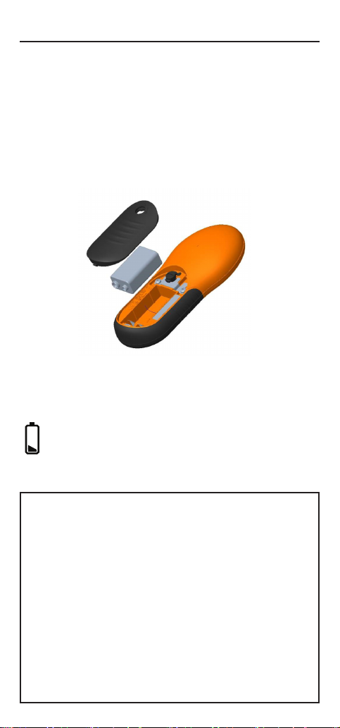
Isætning af baeriet ................................................................ 42
Funkoner ............................................................................... 43
Kontrol af hegnet og fejlsøgning.............................................. 44
Detektering af alarmer ............................................................ 45
Tænde/slukke spændingsgiveren (standby) ............................ 46
Brug af ernbetjeningen med ere spændingsgivere ............. 46
Sådan lføjes en kanal............................................................. 47
Forstå dit elhegn...................................................................... 48
Aald af elektrisk og elektronisk udstyr .................................. 49
Español 50
Lecturas del control remoto .................................................... 50
Instalación de la batería .......................................................... 51
Caracteríscas.......................................................................... 52
Revisando su cerca y encontrando los fallos ........................... 53
Detectando alarmas ................................................................ 54
Encendiendo/ apagando el Energizador (En espera)............... 55
Ulización de su control remoto con varios Energizadores..... 55
Añadir canales ......................................................................... 56
Comprendiendo su cerca eléctrica .......................................... 57
Eliminación de equipo eléctrico y electrónico......................... 58
Svenska 59
Fjärravläsningar ....................................................................... 59
Montera baeriet.................................................................... 60
Funkoner ............................................................................... 61
Kontrollera stängslet och hia fel............................................ 62
Upptäcka larm ......................................................................... 63
Slå på/stänga av aggregatet (standby)..................................... 64
Använda ärrkontrollen med era aggregat............................ 64
Lägga ll en kanal .................................................................... 65
Förstå di elstängsel................................................................ 66
Avfall - elektrisk och elektronisk utrustning ............................ 67
Italiano 68
Signicato dei simboli.............................................................. 68
Installare la baeria................................................................. 69
Caraerische ......................................................................... 70
Verica della recinzione e ricerca guas.................................. 71
Rilevazione degli allarmi.......................................................... 72
Accendere o spegnere (standby) l’elericatore..................... 73
Uso del telecomando con più elericatori ............................ 73
Aggiunta di un elericatore................................................... 74
Capire la recinzione elerica ................................................... 75
Roamazione arezzature Eleriche od Eleroniche............. 76
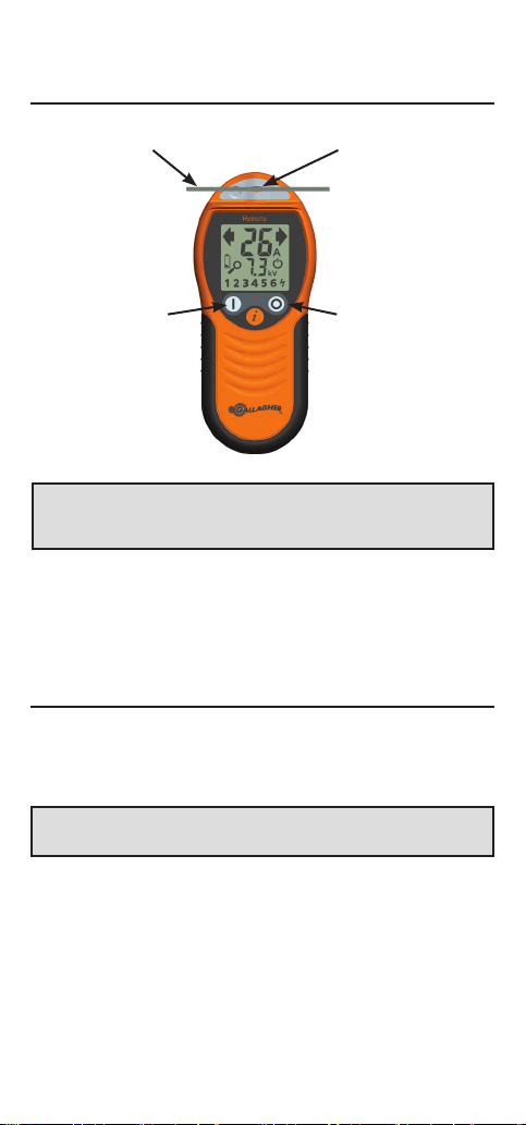
This is the full range of symbols.
The meaning of each symbol is
detailed below.
Liquid Crystal Display
Standby
Indicates the energizer is in
Standby mode.
Energizer status
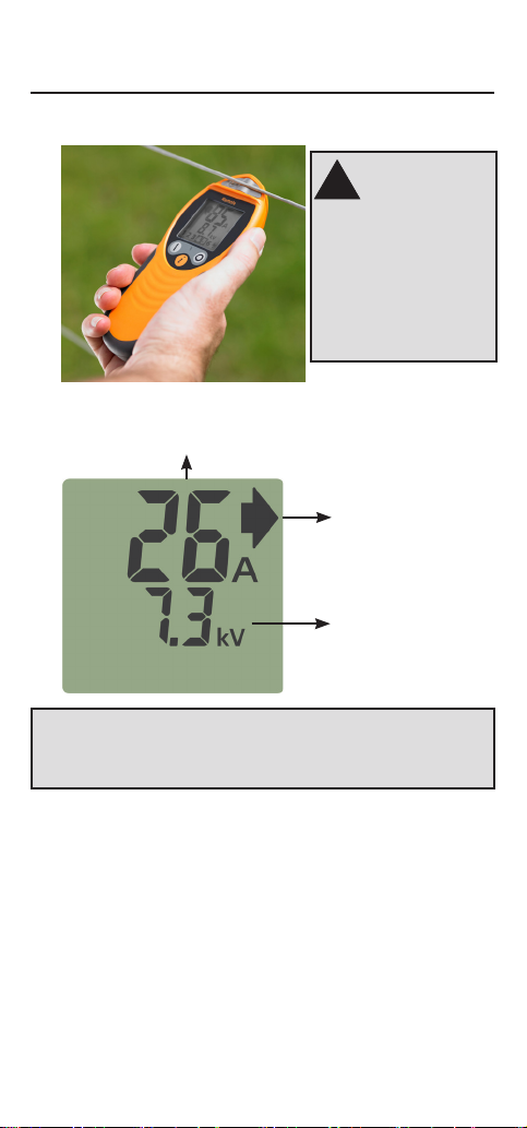
Current Display
Direction of current ow
Voltage Display
Fence Zone indicators
Displays which fence zones are
operating and if they are in
alarm.
Low battery
Remote readings
123456
OR
123456
New channel
Displayed when Remote is
searching for a new energizer.