Gallagher B10 User manual

Manual Gallagher Garden & Pond kit B10 (072330)
Content
Garden & Pond Kit B10 Roadmap...........................................................................................................2
Planning ..............................................................................................................................................2
Contents of the kit ..............................................................................................................................2
Determine the type of fence...............................................................................................................2
Electric fence for garden, yard, ponds or around the aviary..................................................................2
Step 1 – Placing the posts ...................................................................................................................2
Step 2 – Determine the desired height of your fence.........................................................................3
Step 3 – Assemble the wire.................................................................................................................3
Step 4 – Installation of the electric fence device................................................................................4
Step 5 - Warning sign..........................................................................................................................6
Useful tips ...............................................................................................................................................6
For a successful training of your pet, follow these 3 steps.................................................................6
Important information............................................................................................................................6

Garden & Pond Kit B10 Roadmap
Planning
Proper preparation is important. First make a sketch of your fence and determine whether you have
enough materials to make the fence. Follow the steps below for a fast and successful installation of
your electric fence.
Contents of the kit
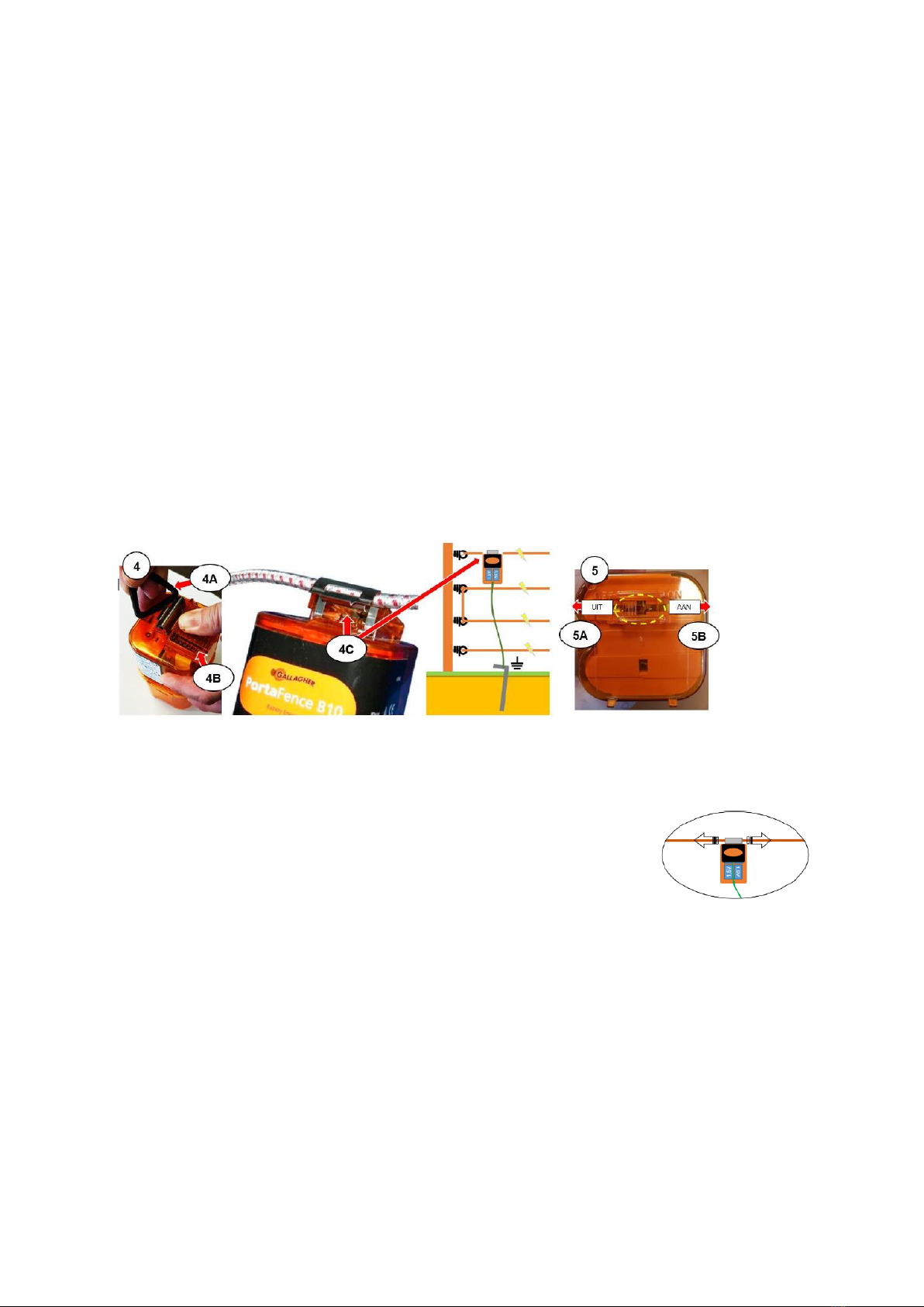
(A) 1 piece Electric fence device B10
(B) 10 pcs. Plastic fence posts (terra)
(C) 25 pcs. Ring insulators
(D) 1 roll 100m Vidoflex (conductive) wire (green)
(E) 1 pc. Earth pin 0.5 metres including 3 metre cable.
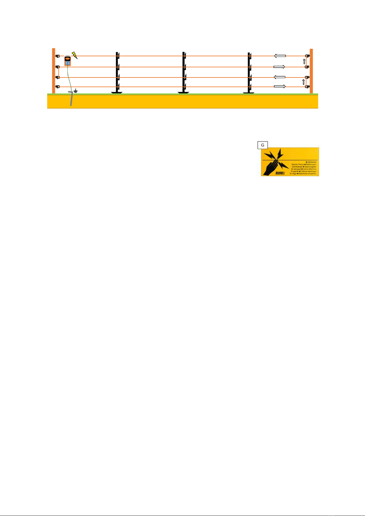
(G) 1 pc. Warning sign
(H) 4 pcs. Vidoflex connector
Determine the type of fence
We distinguish two types of electric fencing,
It’s important to know that a shock is only felt when the animal touches the earth at the same time as
it touches the electric fence, as this completes the circuit.
1. The basic system:
This system is easy to build with (plastic or wooden) posts that are placed in the earth.
The wires in the fence are connected to the electric fence device thanks to a fence connection cable.
The earthing device is grounded thanks to an earth pin in the ground.
With simultaneous contact of the wire and the ground underneath, the circuit is closed and a shock
will be felt.
For the explanation of this type of installation, go to:
Part 1 – Electric fence for garden, yard, ponds or around the aviary in this manual.
2. A plus/minus system:
This system is needed when the wire in the fence is placed at a higher height, such as a fence on a
barrier, wall or in the gutter.
If you place a wire over a fence, an extra wire will always have to be placed for grounding, also known
as the Plus/Minus system.
In such a system, the wires in the fence are connected alternately directly to the electric fence device.
The placement of an earth pin isn’t necessary in such a system.
As soon as at least one plus and one minus wire are touched simultaneously, the circuit will be closed
and a shock will be felt.
Note. The B10 Garden & Pond kit is less suitable for a plus/minus application.
We recommend the Gallagher M10 Garden & Pond Kit for such a system.
For a further explanation of the plus/minus fence, consult the online manual of the Gallagher Garden
& Pond Kit M10 (article number 072347) on www.gallagher.eu.
Electric fence for garden, yard, ponds or around the aviary
Step 1 – Placing the posts
See the image above for further reference of the articles mentioned in this step-by-step plan.
Determine the location of your desired fence and place a plastic pole (B) in the earth every 4 metres.

4m
Tip: To make the fence extra stable, place a (small) wooden pole (X) in the ground as the starting and
finishing pole. You will find a suitable wooden pole at your local garden centre or hardware store.
If you use a wooden post as a start and end post, screw the supplied ring insulator (C) into the post at
the desired wire heights. Your fence starts and ends here.
Step 2 – Determine the desired height of your fence
We recommend a 2-wire fence for small dogs, a 3 to 4-wire fence for large dogs and a 3-wire fence
for cats. The distances between the wires depend on the dog breed, between 15 cm and 35 cm, and
between 15 cm and 20 cm for cats. You will find the average that is often applied to dog and cat
fences below.
Recommended Wire Height for Dogs Recommended Wire Height for Cats
We recommend installing at least 2 wires for shielding an aviary or pond. The wires should be
mounted respectively 20 cm and 40 cm from the ground.
Step 3 – Assemble the wire
Now that all posts are in place you can attach the wire (D).
1. Unroll the wire for approximately 25 cm and make
a loop at the beginning of the wire.
2. Close the loop using the supplied Vidoflex wire
connector, (H) as shown in the illustration here.
3. If the first post is a plastic post (B), hook the loop of the wire to the desired wire height behind
the plastic wire holder.
In case you have placed a wooden starting pole, hook the
loop into the eye of the first ring insulator (C1) which you
have attached to the desired wire height in the wooden
pole.

4. See figure step 1, unroll the wire towards the next plastic post (B) and place the wire in the
wire holder, at the same height, repeat this until the end of the fence.
At the end, insert the wire through the ring insulator eye on the end post (B2) and insert the
wire to the upper ring insulator for the next wire height. Follow the method and direction
according to the arrows in the image.
If you use the plastic post as the end post, hook the wire into the wire holder and bring the
wire to the upper wire holder (B3) and then to the adjacent post again.
Do not cut the wire but guide the wire through the ring insulator or wire holder to the next wire
height and then, via the plastic posts, back to the starting post, continue this process for each
post and next wire height.
Hook the wire through a loop attached with a Vidoflex wire connector in the last insulator or
wire holder, do not tighten the wire too much here, hand tight is sufficient.
Your fence is now ready to be connected to the electric fence device.
Step 4 – Installation of the electric fence device
1. Inserting the batteries
Open the battery housing of the electric fence device and place 6 1.5 V type D Alkaline batteries (not
supplied) according to the instructions (1A) in the housing.
Put the battery housing back.
It is also possible to connect the B10 to a 12Volt battery, for which a separately ordered 12 V Battery
adapter kit (1B) is required (item no. 004747).
Connecting a 12Volt battery (optional)
Follow steps 1C to 1G to install the 12Volt battery adapter kit, remove any existing batteries from the
B10 and place the adapter kit in the designated slot (1C) of the battery housing.

Press the adapter kit contacts firmly against the spring contacts (1D) in the housing. Put the battery
housing back and route the wires from the adapter kit under the ground contact to (1E) outside.
Route the wire between the 3 plastic bars (1F) and behind the plastic clip to the bottom of the electric
fence device. After the complete installation of the system, connect the 2 crocodile clips to a 12 Volt
battery, black on minus (-), red on plus (+).
The system is now turned on.
Warning! The on/off switch of the electric fence device will not work when using the 12 V battery
adapter kit: this is normal. To switch the system off, remove the red crocodile clip from the battery.
2. Connect the green earth cable (included in the electric fence device housing).
Slide the cable shoe from the (green) earth cable onto the earth contact plate (2A).
Route the wire between the 3 plastic bars (2B) and behind the plastic clip to the bottom of the electric
fence device.
3. Installation of the earth cable and earth pin
Choose your desired location on the fence to place the electric fence device,
Place the earth pin (E) at the desired location directly next to the fence in the earth. Let the earth pin
protrude about 5 cm above the ground and place the crocodile clip (3A) of the earth cable on this part.
4. Placing the electric fence device
Remove the black plastic (suspension) bracket (4A) on top of the electric fence device by pressing the
button (4B). Hang the electric fence device on the fence by pressing the button on top again, place
the fence wire in the open metal clip (4C) and release the button. The system is now fully connected.
Tip: To achieve good contact between the electric fence device and the
wire, slide the electric fence device a few times in horizontal motion over the
wire when closing the clip.
5. Switching on the electric fence device
To switch the electric fence device ON or OFF, a switch is located on the underside. For the correct
position, see the ON and OFF text above the switch. As soon as the switch is placed in the ON (5B)
position, your fence is powered, a LED will flash on the electric fence device.
Warning! The on/off switch of the electric fence device will not work when using the 12 V battery
adapter kit: this is normal. To switch the system off, remove the red crocodile clip from the battery.
Warning! There is now electricity on the fence.

Step 5 - Warning sign
Is part of the fence on the street side or in another freely accessible public
area?
In that case, place a supplied ‘warning sign’ (G) in a clearly visible place of
your fence. Use 2 small plastic cable connectors (not supplied) to do this.
To properly test the device and the operation of the fence, we recommend
that you consider purchasing a voltage tester. For the voltage testers, see the gallagher.eu webshop.
No electric impulse?
Check the electric fence device, is it plugged in?
Is the red light on the electric fence device lit?
Is there too much vegetation against the power cord?
Check all connections.
Useful tips
For a successful training of your pet, follow these 3 steps.
1: Power the fence once it has been built. Prevent your pet from having the opportunity to touch the
fence without being corrected by the electrical impulse.
2: Stay in the yard with your pet when you first activate the fence. Call ‘no’ if the animal gets an
impulse. Your voice together with the impulse tells it that it’s bad to touch the fence.
3: It is in the interest of training your pet that shortly after the fence has been placed there has been
contact between the pet and the fence. This way your pet immediately learns that the fence is
forbidden to pass.
Important information
Warning
Read and understand all instructions before using.
Tell your family and neighbours that you have installed an electric fence and how it works.
Instruct all people involved how to turn off the electric fence in the event of an emergency.
The electric fence device must be connected to the galvanised earth pin supplied to ensure
that the installation works perfectly.
Check the local regulations for electrical fencing: these regulations may require a permit
before an electrical fence may be used.
Use double-insulated cable in buildings and in areas where the ground will make the
galvanised wire corrode. Never use the electricity cable used in homes, as it is unsuitable and
will not work.
Risk of electric shock: never connect any other electrical device to your fence at the same
time. Any lightning strike on your fence will then be routed to all other electrical equipment.
Table of contents