Galls ST300 User manual

PLIT301GALLS REV. D 6/18/14
ST300
Street Commander
SIREN AMPLIFIER & LIGHT CONTROLLER
INSTALLATION AND OPERATING INSTRUCTIONS
1340 Russell Cave Road / P.O. Bo 54308 Le ington, KY 40505
Tel: (800) 477-7766 Fa : (800) 944-2557
www.galls.com
Street Thunder™
Street Thunder™Street Thunder™
Street Thunder™

-i-
TABLE OF CONTENTS
INSTALLATION INFORMATION TABLE 1
GENERAL DESCRIPTION 1-2
INSTALLATION 2-17
PACKAGE CONTENTS 2
INSTALLER-SELECTABLE OPTIONS (Amplifier) 3-6
INSTALLER-SELECTABLE OPTIONS (Control ead) 7-8
MOUNTING 9-11
ELECTRICAL CONNECTIONS (Siren Amplifier) 12-15
RECOMMENDED WIRE SIZING C ART 12
SIREN WIRING DIAGRAM 14
OPTIONAL RT WIRING DIAGRAM 15
ELECTRICAL CONNECTIONS (Lights) 16-17
LIG T WIRING DIAGRAM 17
BUTTON LABEL INSERTION 18
OPERATION 19-22
GENERAL 19
SLIDE SWITC 19
PUS BUTTON LIG T CONTROLS 19
SIREN CONTROLS 20-21
VOLUME CONTROLS 22
MICROP ONE 22
AUXILIARY INPUT 22
PARK KILL 22
SPEAKER DIAGNOSTICS 22
SERVICE 23-25
TROUBLES OOTING 23
FUSES 24
SPECIFICATIONS 24
PARTS 25
RETURNS 25
LIMITED WARRANTY 26
SWITC FUNCTION TABLE 26
NOTICE
Due to continuous product improvements, we must reserve the right to change any
specifications and information contained in this manual at any time without notice. Galls
and/or the manufacturer make no warranty of any kind with regard to this manual,
including, but not limited to, the implied warranties of merchantability and fitness for a
particular purpose. Galls and/or the manufacturer shall not be liable for errors contained
herein or for incidental or consequential damages in connection with the furnishing,
performance, or use of this manual.

-1-
Installation Information
MODEL:
AMP S/N:
CONTROL HEAD S/N:
PURCHASE DATE:
INSTALLATION DATE:
INSTALLER:
DEALER:
SIREN OPTION DIP SWITCHES LIGHT CONTROL OPTION JUMPERS
_____ Two-Tone Enabled _____ 8 sec. gun lock S4
_____ Pursuit Disable _____ Momentary S3
_____ Phaser Disabled _____ Normally Closed S3
_____ Negative Park Kill Switching _____ RT on Start-up
_____ Negative Auxiliary Switching _____ Audible Beep disable
_____ Auxiliary Override
_____ F on Start-up
_____ S3 Auto Activate
The ST300 series is a premium remote system that combines the siren amplifier, the
siren controls, and light controls all in one system. A single slim-line remote control
head combines the noise-canceling microphone with a built in siren, as well as many
of the switch and light controls for the vehicle. The control head contains illuminated
switches that change color to indicate status. The face of the control head is sealed
around every push button to help prevent li uid from entering the electronics. The
amplifier is a 200W siren amplifier unit designed for single or dual 100W speaker
use.
The control head contains several distinct controls for operation of vehicle devices.
The slide switch allows uick pursuit mode operation. The far right slide position
can be set up to activate maximum lights and siren for pursuit mode. Five push
buttons allow control of five different lighting or auxiliary functions. Seven
additional push buttons allow full siren operation.
The ST300 series is designed to allow maximum versatility in mounting. The control
head is remote from the siren amplifier and light relay control box, creating a
compact user interface that can be mounted onto the dashboard, overhead, or in the
center console. The amplifier box can then be mounted remotely in the trunk, under
the dashboard, under the seat, or wherever convenient. The control head is available
with an adjustable “U” bracket or with a flange for recessed mounting.
General Description

-2-
(General Description CONT’D)
Siren operating modes include Wail, Yelp, Phaser, Hands Free, and Radio. A noise
canceling PA override is available in all modes. A Manual button allows tone toggle
operation and manual siren control. The Air Horn button will override any siren tone.
The vehicle horn switch may also perform the Manual push button function via an
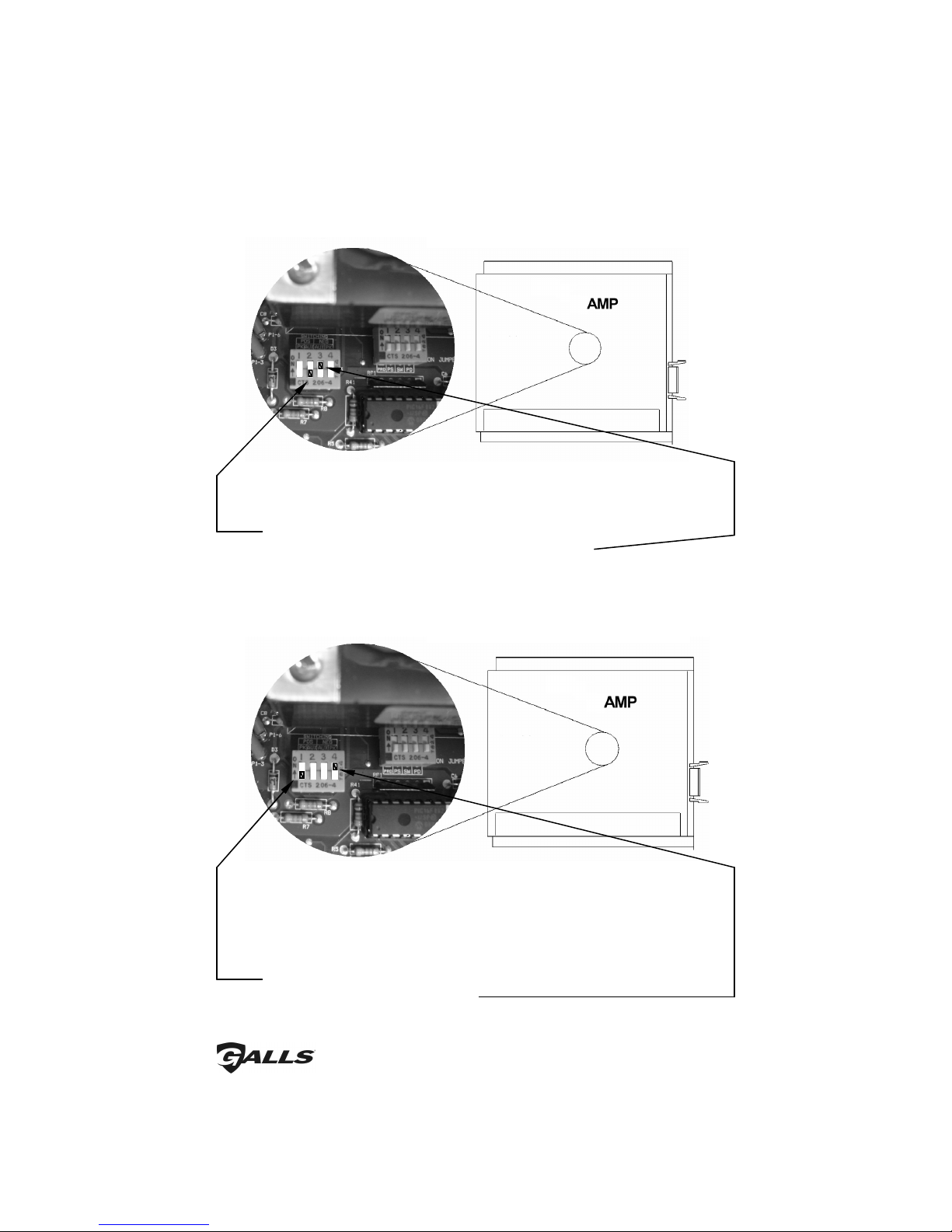
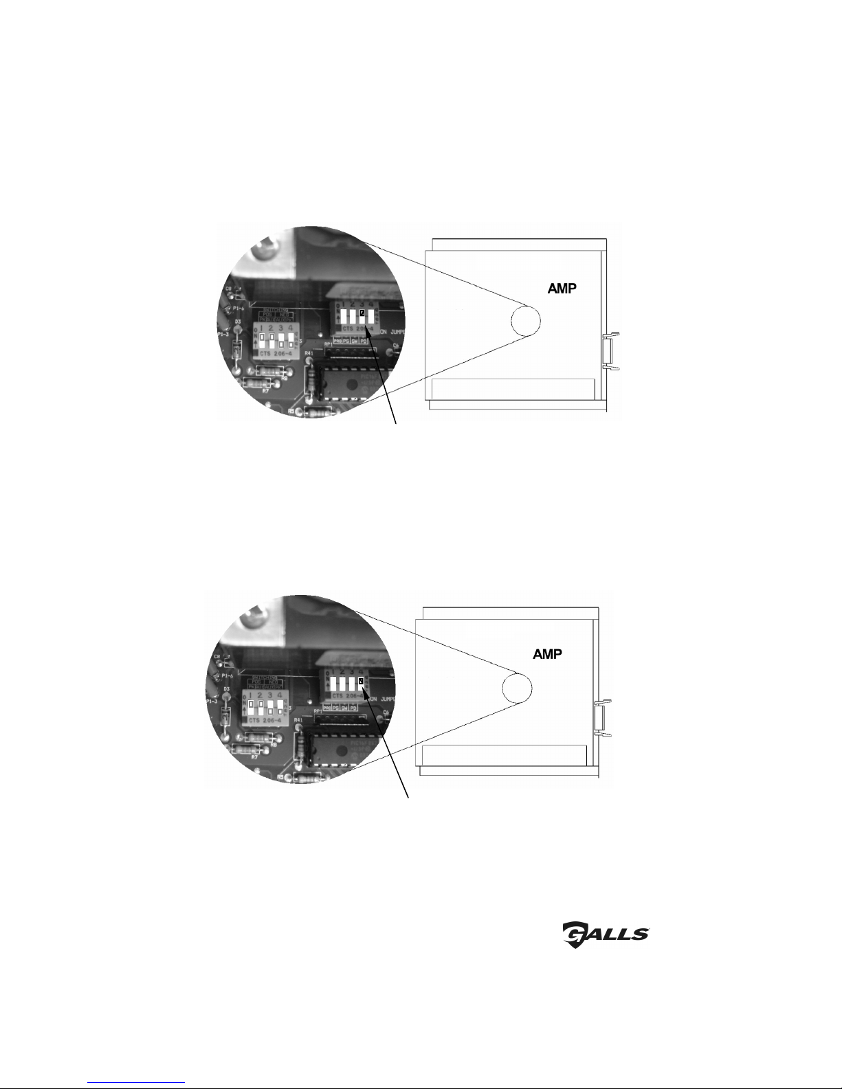
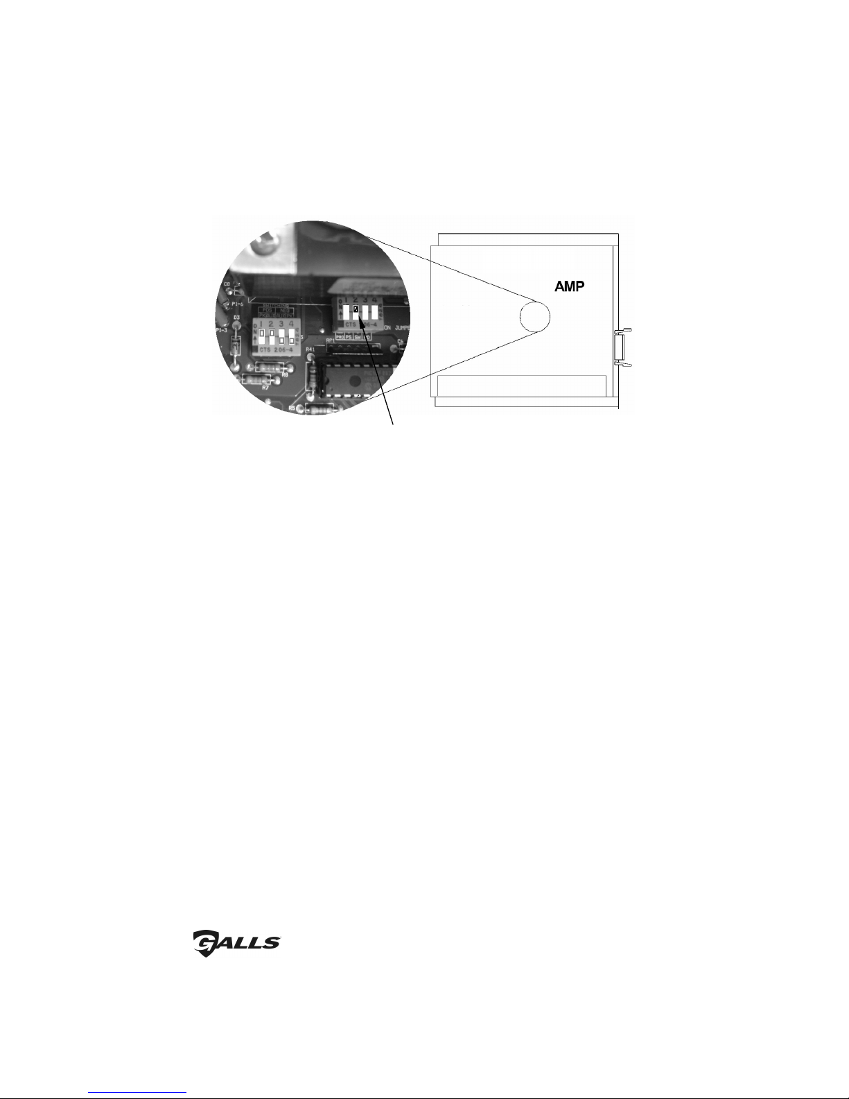
auxiliary input. Twelve option jumpers allow the unit to be fully customized to the
operators' needs. Options include: Phaser vs. Two-Tone, Phaser disable, 8 second
timed gunlock release, momentary vs. lock-on/lock-off switch operation, N.O.
contact vs. N.C. contact, auto horn ring transfer, and many more. A Park Kill option
is provided for connection to a door switch, etc. to disable the siren when exiting the
vehicle. Both a PA volume and a Radio volume are provided.
The ST300 series has been designed with several protection features to provide
exceptional field service. Excessive high or low voltage detection will disable the
siren output, protecting both the amplifier and the speaker. Fused inputs provide
safety against reverse polarity. Speaker diagnostics provides user feedback as well as
shutdown protection against speaker opens and shorts. The first four light output
functions are individually protected with 20A fuses, while the fifth light output
function is protected with a 2A in-line fuse. CAUTION: These protection features
will not guard against overloading the outputs.
Installation
Proper installation of the unit is essential for years of safe, reliable operation.
Please read all instructions before installing the unit. Failure to follow these
instructions can cause serious damage to the unit or vehicle and may void
warranties.
Q alifications - The installer must have a firm knowledge of basic electricity,
vehicle electrical systems, and emergency e uipment.
Keep These Instr ctions - Keep these instructions in the vehicle or other safe
place for future reference. Advise the vehicle
operator of the location.
Unpacking - Immediately inspect the contents for shipping damage. If any
damage is found, alert the carrier immediately.
Contents should include:
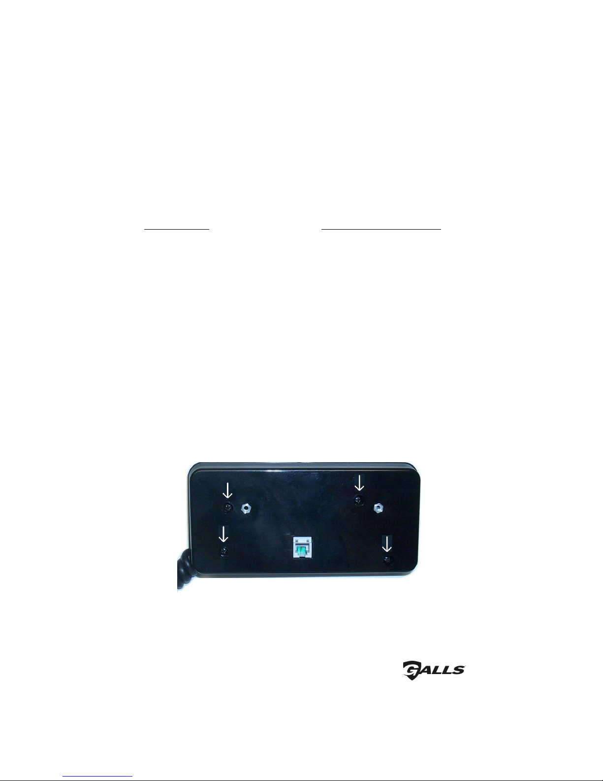
1 - remote control head
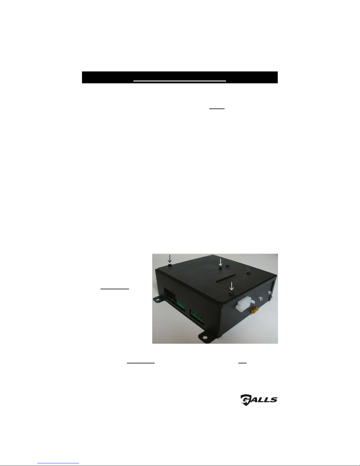
1 - amplifier and light control box
1 - amplifier wire harness with connector
1 - 25’ amplifier communication cable (6-wire telephone style cable)
1 - mounting hardware
1 - “ ” bracket
1 - label set
1 - installation and operating instructions
Please contact your supplier immediately if any components are missing.

-3-
Installer Selectable Options
The ST300 has several options that can be selected during installation. Various
DIP switches and jumpers on the printed circuit board inside the amplifier case,
inside the control head. These options should be set before installation of the
unit.
Siren option DIP switches (located in the amplifier case):
• Auxiliary input polarity
• Park Kill input polarity
• Two-tone replacement of Phaser tone
• Phaser Disable
• Slide Switch Pursuit Disable
Light control option j mpers (located inside the control head)
• Auxiliary control (Manual vs. Horn)
• 8 second timed gun lock release (S4)
• Momentary replacement of lock-on/lock-off switch operation (S3)
• Normally closed contact replacement of normally open (S3)
• Activate Hands Free on start-up
• Activate Horn Ring Transfer on start-up
• Audible beep disable
• S3 Auto Activate on Position L2 & L3 of Slide Switch
SIREN OPTION DIP SWITCHES
Amplifier Cover Removal
CA TION:
DO NOT
OVER-TIGHTEN
SCREWS!
Loosen the three protr ding Philips head screws located on the top of the
amplifier unit. Slide the cover off.

-4-
(Installer Selectable Options CONT’D)
Diagram showing NEG A X set up
Diagram showing NEG PK set up
A xiliary Inp t Polarity
Applying a positive voltage to the green wire normally activates the auxiliary
function (Air Horn standard/MANUAL function optional). To have the AUX
function instead activate when the green wire is connected to ground (negative)
.
1. Turn “AUX POS” DIP switch off (shown above).
2. Turn “AUX NEG” DIP switch on (shown above).
The wiring diagram on page 14 shows two connection examples
The Park Kill (Cutout) Input turns off any siren tone output when activated, and
remains off until a control is activated or changed. The wiring diagram on page
14 shows two connection examples.
Connecting the white wire to positive (+12 VDC) normally activates the Park
Kill input. To have it activate instead when the white wire is connected to
ground (negative).
1. Turn “PK POS” DIP switch off.
2. Turn “PK NEG” DIP switch on.
(See Amp ifier diagram above)
Park Kill Inp t Polarity

-5-
(Installer Selectable Options CONT’D)
Two-Tone
Phaser Disable
If desired, the Phaser sound can be replaced with a Two-Tone sound. This can
be done by turning on (up position) DIP switch #3 in the amplifier (labeled SW).
(See Amp ifier diagram above)
If desired, the Phaser function can be completely disabled by turning on (up
position) DIP switch #4 in the amplifier (labeled PD). This will also disable the
manual button while the siren is in Phaser mode (which normally would
produce a Two-Tone sound).
(See Amp ifier diagram above)

-6-
(Installer Selectable Options CONT’D)
P rs it Disable (Siren)
The farthest right slide switch position (L3) will normally activate the siren
output in the wail mode, along with all three light functions. Automatic
activation of the siren and arrow stick can be disabled. If you prefer to NOT
have the siren and arrow stick automatically activated when the slide switch is
moved to position three, move Dip switch #2 in the amplifier (labeled PS) to the
“UP” position. (See diagram above).

-7-
CONTROL HEAD OPTION JUMPERS
The control heads are shipped with the standard features listed below. The seven
jumpers are all installed across both pins when the siren is shipped. By moving
the jumpers onto only one pin the alternate operation may be selected. (S3 Auto
Activation is achieved by removing the "Momentary" and "Normally Closed"
jumpers and placing one of them across both of the first pins.)
(Installer Selectable Options CONT’D)
Standard Feature Movin Jumper to One Pin Only
Auxiliary wire activates orn Function Auxiliary wire activates Manual
Function
S4 is a standard push-on/push-off switch S4 closes for 8 seconds when pushed
S3 is a standard push-on/push-off switch S3 becomes a momentary switch
S3 is normally open when off S3 becomes closed when off
ands Free function off when powered up ands Free function is on when unit
powered up
orn Ring Transfer (S5) is off when powered up orn Ring Transfer is auto selected on
start-up
Audible beep heard when buttons are pressed Audible beep disabled
S3 functions activated only with S3 switch S3 functions activated when slider in
L2 or L3 positions
Amplifier Cover Removal
Remove the four Philip head screws recessed in the back of the control head unit.
CAREFULLY remove rear cover, use caution so as not to lift circuit board and
membrane switch away from front faceplate. Locate the 7 jumpers located near
the microphone coil cord strain relief.

-8-
(Installer Selectable Options CONT’D)
A xiliary control (Man al vs. Horn) - The green auxiliary wire in the siren
amplifier harness is typically connected to the vehicle horn, and normally
provides remote activation of the air horn for all siren modes except Hands
Free (HF) mode. In the HF mode, the auxiliary wire will make the siren step
through from Standby to Wail to Yelp to Phaser. The auxiliary wire may be
optionally selected to duplicate the Manual push button instead of the Horn.
8 second timed g n lock release (S4) - The amplifier is shipped with the fourth
push button (S4) as a standard on/off button. It can be optionally selected to
stay activated for only 8 seconds when pressed.
Momentary replacement of lock-on/lock-off switch operation (S3) - The
amplifier is shipped with the third push button (S3) as a standard lock-on/
lock-off switch. It can be changed to momentary operation, thus only being
active while being pressed in.
Normally open contact replacement of normally closed switch (S3) - The
amplifier is shipped with the third push button (S3) as a normally open
contact, which closes when pressed. It can be changed to a normally closed
contact that opens when pressed.
Activate Hands Free on start- p - If you wish to have the siren automatically
activated in Hands Free Mode when the control head is powered up, you can
select this option.
Activate Horn Ring Transfer on start- p (S5) - If you wish to have the fifth
push button (S5) automatically activated when the control head is powered
up, you can select this option. S5 may be connected to the horn ring transfer
relay if you wish to turn the Horn Ring Transfer feature on and off. (Refer to
the wiring diagram on page 14).
A dible beep disable - The audible beep heard when the buttons in the
control head are pressed can be disabled.
S3 A to Activate – S3 will turn on when the slide switch is in positions L2 &
L3 and then will turn off when the switch is moved back to L1 or off.
These two jumpers are shown
moved from their default
position to only one pin.
- Auxillary control
- 8 Second (S4)
- Momentary (S3)
- Normally closed contact (S3)
- ands Free on start up
- orn Ring Transfer on start up
- Audible beep disable
S3 Auto Activate -
place one jumper
over both these
pins

-9-
Mountin
WARNING
DO NOT mount in air bag deployment area.
Devices should be mounted only in locations listed in SAE standard J1849.
Controls should be placed within convenient reach of the driver.
Assure clearances before drilling in vehicle.
Sound levels produced by attached speakers can cause permanent hearing loss.
SAFETY PRECAUTIONS
For the safety of the insta er, vehic e operator, passengers and the community
p ease observe the fo owing safety precautions. Failure to follow all safety
precautions and instructions may result in property damage, injury or death.
SIREN AMPLIFIER & RELAY CONTROL BOX
• The LCS800 amplifier should be
mounted in a location such as the
driver compartment firewall,
under the seat, or in the trunk.
• Do not mount the amplifier in the
engine compartment or in an area
that would be allowed direct
exposure to weather elements.
• Choose a mounting location away
from any air bag deployment
areas.
• Assure ade uate ventilation to prevent overheating.
1. The amplifier unit is provided with a mounting flange that contains four 1/4"
holes.
2. Using the amplifier unit itself as a template, mark the location of the four
mounting holes to be drilled.
3. Check for obstructions behind the mounting hole locations and drill the four
mounting holes and secure the amplifier using appropriate hardware (not
supplied).
4. Be sure that all wiring harness connections are made prior to connecting the
harness to the amplifier unit.

-10-
(Mountin CONT’D)
STANDARD CONTROL HEAD
The standard control head comes with two interchangeable “U” brackets.
1. Using one of the two “U” brackets as a template, mark at least two mounting
holes on your mounting surface.
2. Drill the mounting holes in the vehicle taking care to check the backside of the
surface you are drilling into.
3. Mount one of the “U” bracket using installer-supplied hardware.
4. If the control head option jumpers have not been previously set, refer to the
Installer Selectable Options section on pages 7-8.
5. Screw the second “U” bracket to the backside of the control head using the two
#8 screws provided.
6. The “U”
bracket on the
back of the
control head
can
now be fastened to
the “U” bracket
previously
mounted on the
vehicle using the
two ¼” screws,
two flat washers,
two lock washers,
and two nuts
provided.
7. Once fastened together, adjust the control head by rotating the “U” brackets
and/or sliding the “U” brackets closer or farther apart. Tighten ¼” screws.

-11-
(Mountin CONT’D)
MICROPHONE BRACKET
A metal clip is provided for mounting the microphone. Choose a location
convenient to the operator and away from any air bag deployment areas. Using
the mounting clip as a template, mark the two holes to be drilled. Using a 1/8"
drill bit, drill the two mounting holes. Install the two #6 screws provided with
the bracket.

-12-
Electrical Connections
Wire Size and Termination
The wiring diagrams on pages 14 and 17 show the minimum wire size used for
each connection, along with recommended lead color. If the wire is longer
than 10 ft., use the next larger wire size. Use only high uality crimp
connectors. Make sure all connections are tight. Route wiring to prevent wear,
overheating, and interference with air bag deployment. Use grommets and
sealant when passing through compartment walls. Minimize the number of
splices to reduce voltage drop. Ground connections should only be made to
substantial chassis components, preferably directly to the negative of the
vehicle battery. Install and check all wiring before connection to vehicle
battery. SEE THE TABLE BELOW FOR CORRECT WIRE SIZING!
RECOMMENDED WIRE SIZE - AMP CAPACITY &
CONSTRUCTION
Ampacity Range SAE Wire Size Gauge/No. of Strands
5A - 10A #16 29/19
10A - 15A #14 27/19
15A - 30A #12 25/19
30A - 40A #10 23/19
40A - 50A #8 21/19
All conductors should be constructed of stranded copper with thermoplastic insulation.
CAUTION: All wires sho ld be rated for at least 125% of their maxim m c rrent load.
All wires connected to the positive terminal of the battery sho ld be f sed at the battery
for their rated load. The load can be calculated by adding all lamp wattages and dividing by
13. Load (Amps) = Total Watts / 13 volts. Do not use 1/4" diameter glass fuses, as they are
not suitable for continuous duty above 20 amps.
SIREN AMPLIFIER
Siren electrical power
connections to the amplifier
are made using a removable
connector located on the
back of the amplifier case.
Communication between the
control head and the
amplifier are made via a
communications cable with
an RJ11 jack.
CA TION: Please note that this
cable IS NOT a standard telephone
cord and CANNOT be replaced with one. You should make all electrical
connections to the power connector before installing the connector on the unit.
If the unit needs service, both the communication cable and the power
connector can be easily removed without unwiring the connector.

-13-
(Electrical Connections CONT’D)
The power supply of the siren unit must be capable of delivering peak currents up
to 50 amps for ade uate short circuit protection and reliable operation. The
preferred source is directly at the vehicle battery. The unit is internally fused.
The wiring diagram on the next page shows detail of how to wire the power
connector on the amplifier to the vehicle. The communication cable should have
one end plugged into the amplifier (telephone style jack) and the other end
plugged into the control head.
Siren
Wiring Connections:
BLACK LEADS: You MUST connect BOTH black wires when using two 100W driver speakers.
Connect to the negative of the battery, or to a good chassis ground. Be sure to use minimum
size #14 AWG wire.
RED LEADS: You MUST connect BOTH red wires when using two 100W driver speakers. Connect
to the positive of the battery, or to a high current power buss. A power relay may also be
used. Be sure to use minimum size #14 AWG wire.
BROWN LEADS: Connect one lead to each terminal or lead of the speaker. Be sure to use minimum
size #14 AWG wire. If connecting a second speaker in parallel, yo m st observe the
polarity of the speakers (phasing). Be s re that the positive terminals of both speakers
are connected together to the same brown wire from the siren. In which case, the
negative terminals of both speakers would also be connected together to the other brown
wire.
PINK LEAD: Connect the pink wire to you ignition-controlled power (or other switched power
source). This will turn the power to your unit on and off.
Siren Optional Connections:
BLUE LEADS: Use for radio repeat. Connect one blue lead to each terminal of the radio speaker or
output connector of the radio. Use #18 AWG wire.
GREEN LEAD: (AUX) Use if you would like to activate the siren’s AIR HORN when the vehicle
horn is pressed. Connect to horn ring circuit or other remote switch. Circuit may be positive
or negative with proper jumper selection. See A xiliary Inp t Polarity section on page 4
for jumper details. NOTE: Cut lead short if not used & insulate with electrical tape.
Optionally this may be used to mimic the Manual button function when the vehicle’s horn is
pressed. See A xiliary control on pages 7-8 for Control Head jumper setting.
WHITE LEAD: Used for Park Kill (Cut-off). Connect to dome light or added door switch. Circuit
may be positive or negative with proper jumper selection. See INSTALLER-SELECTABLE
OPTION section (page 4) for jumper details.
NOTE: Be sure to cut lead short if not used and insulate with electrical tape.
ORANGE LEAD: Used for Horn Ring Transfer Relay, or other low current output. This output is
activated by pushbutton switch S5. Optionally it can be ON at siren boot (see Activate
Horn Ring Transfer on start- p on pages 7-8). The HRT will deactivate the vehicle’s
horn when it is on (S5 on). This allows the driver to use the horn ring to control the siren
without activating the vehicle’s horn.
Connect the Orange wire to the Horn Ring Transfer Relay or other low current device
(Maxim m 2A). This output may also be used to drive an external relay when higher
current is re uired. NOTE: Cut lead short if not used & insulate with electrical tape.
See the HRT Wiring Diagram on page 15 for more detail.

-14-
12 - Brown (#14 AWG)
Siren Wiring Diagram
Positive
Switching
AUX
Positive Switching AUX
orn Jumper Selected
+12 VDC
+12 VDC
Ignition controlled
power or other
switched power source
orn
Switch/Relay
Negative Switching AUX
orn Jumper Selected
+12 VDC
orn
Switch/Relay
OR
VE ICLE
ORN
VE ICLE
ORN
Negative
Switching
AUX
+12 VDC
Optional Relay Activated
When PB5 is Turned On
To igh Current Device
5 - Black (#14 AWG)
SIREN
AMPLIFIER
11 - Pink (#18 AWG)
10 - Orange (#18 AWG)
9 - Green (#18 AWG) OR
8 - White (#18 AWG)
7 - Brown (#14 AWG)
6 - Blue (#18 AWG)
1 - Red (#14 AWG)
4 - Red (#14 AWG)
3 - Blue (#18 AWG)
2 - Black (#14 AWG)
Positive Switching PK
Jumper Selected
+12 VDC
2 Amp fuse SPEAKER 1
11 O MS
+
SPEAKER 2
11 O MS
+
Door Switch Dome
Light
Negative Switching PK
Jumper Selected
RADIO
+
Connect the Blue wires to
the terminals of speaker or
to the output jack of radio
+
BATTERY
OR
Added Door
Switch
(Electrical Connections CONT’D)

-15-
(Electrical Connections CONT’D)
Horn Ring Transfer (HRT) Wiring Diagram
Use this wirin dia ram if you are connectin the Oran e wire to utilize the Horn Rin Transfer Feature.
This feature de-activates the vehicle horn while pushbutton switch S5 is activated. The dia ram below
shows wirin for both positive and round-side switched horns, usin an installer-supplied relay.
Ground Side
orn Switch
Negative Switching
AUX Jumper Selected
+12 VDC
VE ICLE
ORN
Cut your horn wire
here and insert the
installer supplied relay
Positive Side
orn Switch
Connect like
this for
Positive Side
Horn Switch
Connect like
this for
Ground Side
Horn Switch
OR
VE ICLE
ORN
Cut your horn wire
here and insert the
installer supplied relay
Green Wire From Amp
Orange Wire From Amp
Green Wire From Amp
Positive Switching
AUX Jumper Selected
2 Amp fuse
+12 VDC
User Supplied Optional SPDT Relays
(Opened When S5 Button Activated)
2 Amp fuse

-16-
MAN PHSRHFHORN WAIL YELP RADIO
S1 S2 S3 S4 S5
Control ead
Off L1 L1 & L2 L1, L2, & L3
OFF L1 L2 L3
(Electrical Connections CONT’D)
(REFER TO LIGHT WIRE DIAGRAM ON NEXT PAGE, AS WELL AS
TO WIRE SIZE TABLE ON PAGE 12 FOR PROPER WIRE SIZES!)
The electrical connections for input power, slide switch outputs, and the push button
outputs are made to the control box (amplifier) using terminal blocks (top diagram
above).
+12 VDC Input: Connect +12VDC to the 3 large barrier style terminal blocks.
When controlling lights with a large amount of current (>15A) power should
be supplied to all three inputs.
L1, L2, L3 (Center Terminal Block): Connect lights to L1-L3 outputs (20A
max each) that you wish to activate in the corresponding slide switch
positions. (Note: the second slide switch position activates both L1 and L2
and the third slide switch position activates L1, L2 and L3).
S1, S2, S3, S4 (Right Terminal Block): Connect lights to S1-S4 outputs (20A
max each) that you wish to activate with corresponding pushbutton switches
S1-S4.
S5 switches power (low current - 2A or less) to the Orange wire in the wiring
harness. It has an in-line 2A fuse. Typically the horn ring transfer relay is
connected to this switch. This output may also be used to drive an external
relay when higher current is re uired.
LIGHT RELAY CONTROL BOX CONNECTIONS (Amplifier box)

-17-
AMPLIFIER
S4 - (#12-16 AWG)
3 - Red (#8-12 AWG)
+
BATTERY
Audio/Visual
Warning Device
S3 - (#12-16 AWG)
S3 - (#12-16 AWG)
S3 - (#12-16 AWG)
L3 - (#12-16 AWG)
L2 - (#12-16 AWG)
L1 - (#12-16 AWG)
20A
20A
20A
20A
20A
20A
20A
2 - Red (#8-12 AWG)
1 - Red (#8-12 AWG)
Lights to be activated by
push button switch S4
Lights to be activated by
push button switch S3
Audio/Visual
Warning Device
Lights to be activated by
push button switch S2
Audio/Visual
Warning Device
Lights to be activated by
push button switch S1
Audio/Visual
Warning Device
Lights only to be activated by
slide switch position 3
Audio/Visual
Warning Device
Lights only to be activated in both
slide switch positions 2 & 3
Audio/Visual
Warning Device
Lights to be activated in slide
switch positions 1, 2, & 3
Audio/Visual
Warning Device
SEE PAGE 12 FOR
CORRECT WIRE SIZING!!!
Light Wiring Diagram
(Electrical Connections CONT’D)

-18-
Testing - Test a siren functions after insta ation to
assure proper operation. Test vehic e operation
to assure no damage to vehic e.
Once the wire connections have been made to S1 through S5, labels can be
inserted into the switches. The product is shipped with 30 different labels for
these push buttons. Select the desired label inserts (provided). Insert the label
into each button and tuck it under the lip of the switch.
The siren labels come pre-installed and may be used for reference when inserting
light function labels
Label Insertion
Table of contents
Other Galls Amplifier manuals