Galls Street Thunder ST240 User manual

PLITSTR312 REV. D 10/28/13
SIREN
SIRENSIREN
SIREN
Installation and Operating Instructions
Installation and Operating InstructionsInstallation and Operating Instructions
Installation and Operating Instructions
ST240
ST240ST240
ST240
Street Thunder
Street ThunderStreet Thunder
Street Thunder
™
™™
™
1340 Russell Cave Road / P.O. Box 54308 Lex ngton, KY 40505
Tel: (800) 477-7766 Fax: (800) 944-2557
www.galls.com
NOTICE
Due to continuous product improvements, we must reserve the right to change any
specifications and information contained in this manual at any time without notice. Galls
and/or the manufacturer make no warranty of any kind with regard to this manual, including,
but not limited to, the implied warranties of merchantability and fitness for a particular purpose.
Galls and/or the manufacturer shall not be liable for errors contained herein or for incidental or
consequential damages in connection with the furnishing, performance, or use of this manual.

-i-
Installation Information
MODEL: ST240 Ser al #:
PURCHASE DATE:
INSTALLATION DATE:
INSTALLER:
DEALER:
Model and serial number located on bottom of unit
TABLE OF CONTENTS
GENERAL DESCRIPTION 1
INSTALLATION NOTES 1
MOUNTING TIPS 1
ELECTRICAL CONNECTIONS 2-3
Wiring Guide 2
Wiring Diagram 2
andatory Connections 3
Optional Connections 3
INSTALLER SELECTABLE OPTIONS 4-5
DIP Switch Settings (AUX & P/K Polarity) 4
Optional Tone Programming 4-5
OPERATION 6-7
Power/PA 6
Selector Switch 6
anual/Horn Button 7
Radio Volume 7
icrophone 7
Auxiliary Input 7
Park-Kill Cutout 7
TROUBLESHOOTING 8
Speaker Diagnostics 8
Troubleshooting Chart 8
SPECIFICATIONS 9
SERVICE 9-10
Parts 9
Warranty 10

-1-
Installation Notes
The ST240 Siren Amplifier is a premium 200W unit designed for dual 100W speaker
use. The primary operating modes are Thunder, Yelp, Wail, Hands Free, anual, PA,
and Radio. A Noise Canceling PA Override and push-button Horn Override are
available in all modes. A manual push-button is provided for push-on/push-off tone
toggle operation in the Thunder, Yelp, and Wail modes. It also allows manual siren
control in the anual or PA modes. Any siren tone can be re-programmed to a
more desired tone. Another feature allows cycling through Wail, Yelp, Thunder, and
Standby by providing a signal to the horn ring auxiliary wire when the function switch
is in the Hands Free (HF) position. A Park Kill option is provided for connection to a
door switch, etc. to disable the siren when exiting the vehicle. Radio and PA volume
controls are provided on the front panel. The front panel is backlighted with LED's
for night visibility. This compact unit utilizes short circuit, high voltage, low voltage,
and reverse polarity protection systems for maximum service life.
General Description
Proper installation of the unit is essential for years of safe, reliable operation. Please
read all instruction efore installing the unit. Failure to follow these instructions can
cause serious damage to the unit or vehicle and may void warranties.
Qualifications - The installer must have a firm knowledge of basic electricity, vehicle
electrical systems and emergency equipment.
Keep These Instructions - Keep these instructions in the vehicle or other safe place
for future reference. Advise the vehicle operator of the location.
Unpacking - Inspect contents for shipping damage. If found, alert carrier
immediately. Contents should include unit with microphone, mounting bracket w/
hardware, microphone bracket with 2 screws, wiring connector, and these
instructions. Contact your supplier immediately if any components are missing.
Mounting Tips
• ount in a location with adequate ventilation to prevent overheating.
• Devices should be mounted only in locations listed in SAE standard J1849.
• Controls should be placed within convenient reach of the driver.
• Assure clearances before drilling in vehicle.
• Sound levels produced by attached speakers can cause permanent hearing loss.
• Never operate this unit without adequate hearing protection for you and others
in the area. (OSHA 1910.95)
• Consider wire routing and access to connections.
• Install mounting bracket to vehicle using 1/4" hardware (not supplied).

-2-
Wire Size and Termination
Electrical connections to this unit are made through the green 12-terminal
connector located in the rear of the unit (See below - Part # CPSS-153).
Examine the charts below to determine the proper gauge of the wire to use. Please
review the following recommendations when making your electrical connections:
• For safety and reliability we highly recommend that you always use both Power
terminals (1 & 2) and both Ground terminals (3 & 4).
• Use only high quality crimp connectors. ake sure all connections are tight.
• inimize the number of splices to reduce voltage drop.
• Route wiring to prevent wear, overheating, and interference with air bag
deployment.
• Use grommets and sealant when passing through compartment walls.
• Ground connections should be made directly to the negative of the vehicle
battery. Where not possible, only connect to substantial chassis components.
• Install and check all wiring before connection to vehicle battery.
• CAUTION: All wires should e rated for at least 125% of their maximum current
load. All wires connected to the positive terminal of the attery should e fused
at the attery for their rated load.
• Review the charts below that indicate the recommended wire gauge, based
upon the length of the wire run and the current that will pass through the wire.
Term nal
Descr pt on Typ cal
Color
Typ cal
Current
1 Power Red 10A 20A
Total
2 Power Red 10A
3 Ground Black 10A
4 Ground Black 10A
5 Speaker 1 Brown 4A
6 Speaker 2 Brown 4A
7 A X In Green 3A
8 A X Out Orange 3A
9 Radio Repeat Blue 0.1A
10 Radio Repeat Blue 0.1A
11 Backlighting Yellow 0.1A
12 Park/Kill Input White 0.1A
20A
Total
WIRING GUIDE
Current
10'
20'
25'
< 2.0A 22 AWG 18 AWG 18 AWG
2.0-4.0A 18 AWG 16 AWG 16 AWG
4.1-5.5A 18 AWG 16 AWG 14 AWG
5.6-8.0A 16 AWG 14 AWG 14 AWG
8.1-12.0A 16 AWG 12 AWG 12 AWG
RECOMMENDED WIRE GAUGE
Electrical Connections
Backlighting Power
A X In
Factory
Horn
Relay
Ground
Power
+
-
20A
Fuse
Ignition Switch
BATTERY
12V
POS
NEG
SS700
Cut Factory Wire
2 Way
Rad o
Speaker
-
+OR
Factory Horn
1211
Park Kill
A X O T
108765
4
3
21 9
WARNING: ENS RE CONNECTOR IS F LLY INSERTED & SCREWS LOCKED
AUX POLARITY
TONE
SELECT
PK POLARITY
CPSS-153
(Please note that this is an upside-down view)
(Please note t at t is diagram references t e connector wit t e siren UPSIDE-DOWN)
(SIREN TOP)

-3-
(Electrical Connections CONT’D)
For ease of installation, you can remove
the green connector from the siren while
connecting your wires. Please note that
when referencing terminal numbers using
the wiring diagram on the previous page,
the siren should be held upside down so
the screw heads face UP, as pictured to
the right.
Connections to the terminal block are summarized both in the chart and in the
wiring diagram on the previous page. For more detailed information, review the
section below.
Mandatory Electrical Connections
Ground - Connect terminals 3 & 4 to the negative terminal of the battery.
(You MUST connect oth of these terminals!!)
Power - Connect terminals 1 & 2 to a 10-16VDC ignition switched power source
capable of supplying 20A. Be sure to use minimum size #14 AWG wire.
(You MUST connect oth of these terminals!!)
Speaker - Connect terminals 5 and 6 to your siren speaker.
(You MUST connect oth of these terminals!!)
OPTIONAL ELECTRICAL CONNECTIONS
AUX IN/OUT - These terminals are typically connected to the steering wheel
horn relay. They allow for several functions including siren
operation in HF mode (see page 6) Air Horn activation, or
anual “step up” function (see page 5).
If you will be using any of these features, cut the wire that
connects the horn relay to the horn. Connect the side from the
relay to terminal 7. Connect the side from the horn to terminal 8.
Review the wiring diagram above and ensure that you have the
AUX Polarity DIP switch set for the correct polarity (see page 4).
(You MUST connect oth of these terminals as descri ed
a ove for proper operation of your vehicle horn!!)
Radio Repeat - If you would like the ability to re-broadcast your two-way radio
over your siren speaker, connect terminals 9 & 10 to the two-way
radio speaker or output connector of the two-way radio.
Backlighting - Connect terminal 11 to the dash lights, ignition switched power,
or other switched 10-16VDC power source. This controls the
backlighting for the face of the siren.
Park/Kill Feature - If you would like the siren to automatically disengage when the
vehicle door is opened or when the vehicle is placed into park,
connect terminal 12 to the dome light, added door switch, or
added park switch. Review the wiring diagram on the previous
page and ensure that you have the PK Polarity DIP switch set for
the correct polarity (see next page).
CPSS-153
(Please note that this is an upside-down view)

-4-
The ST240 has several options that can be selected prior to installation by using
either the two DIP switches located on the
back of the unit, or by using the “tone
programming” button on the back in
combination with the knob and/or buttons on
the front of the unit. These options should be
set before installing the siren in the vehicle.
DIP Switch Settings:
Auxiliary AND Park-Kill Input Polarity
The Auxiliary input (terminal #7) and Park Kill input (terminal #12) are normally
activated by applying a positive voltage to each wire. If you would like to activate
either function by connecting to ground (negative) instead, use the DIP switches
located on the back of the siren.
The default setting for both switches (Positive Switching)
is such that the DIP switches are flipped AWAY from the
closest edge of the siren (i.e. DOWN in the picture to
the right). To have either function activated when the
input is grounded, flip the corresponding switch in the
opposite direction (TOWARDS the edge of the siren/UP).
NEG
POS
P/K
POLARITY
AUX
POLARITY
Installer Selectable Options
Optional Tone Programming
The ST240 will produce 7 different tones/sounds by activating its various functions:
Function Default Tone
Thunder Step Up
(THUNDER+MAN)
Two-Tone
THUNDER Thunder
YELP Yelp
WAIL Wail
MANUAL Ramp Up
HORN Air Horn
AUX Air Horn
Each of these functions can be reprogrammed for a different tone, if desired. To
change the sounds for any of the functions, proceed below.
1. Power the unit up.
2. Activate the function you wish to change.
• To change the tone for the THUNDER, WAIL, and YELP functions, rotate the
selector knob into the corresponding position.
• For the ANUAL, HORN, or AUX functions, rotate the selector knob into
the ANUAL or PA position, then press and hold the MANUAL button,
HORN button, or steering wheel horn, respectively.
• For the Thunder Step Up function, rotate the knob into the THUNDER
position, then press and release the MANUAL button.
The tone currently programmed for that function will sound.
3. The Tone Program button can be found above the DIP
switches on the rear of the siren. Using a paper clip, press and
release it to cycle through the list of optional tones. Review
the chart on the following page for a list of optional tones.
4. De-activate the function to save the new tone.
Tone Program Button

-5-
1
WAIL (Wail default) §, *, †
2
YELP (Yelp default) §, *
3
TH NDER (THUNDER default)
4
TWO-TONE
(THUNDER Step Up
default)
5
MECHANICAL WAIL
(FIRE ENGINE)
†
7
HOOT
8
RAPID HOOT
9
AIR HORN & YELP
10
GHOST
11
RAPID GHOST
12
SINGLE AIR HORN
13
SINGLE Q ICK
14
DO BLE POST POP AIR HORN
15
TWO TONE AIR HORN
16
STANDARD AIR HORN
Tones For WAIL, YELP, and
THUNDER, and Thunder Step-Up
Funct on
§ = SAE approved
* = California Title 13 approved
† = See below
6
MAX YELP §, *
17
CONTIN O S TONE
18
CONTIN O S BEEP
Tones For MANUAL Button & AUX W re
1
STANDARD AIR HORN (AUX default)
2
LOW FREQ ENCY AIR HORN
3
RAPID AIR HORN
4
AIR HORN II
5
DO BLE POST POP AIR HORN
6
SINGLE AIR HORN
7
SINGLE Q ICK AIR HORN
8
TWO TONE AIR HORN
9
MAN AL (MANUA default) *
10
MECHANICAL MAN AL
(FIRE ENGINE)
Tones for HORN Button
1
STANDARD AIR HORN (default)
2
LOW FREQ ENCY AIR HORN
3
RAPID AIR HORN
4
AIR HORN II
5
DO BLE POST POP AIR HORN
6
SINGLE AIR HORN
7
SINGLE Q ICK AIR HORN
8
TWO TONE AIR HORN
►►►►
System Reset
◄◄◄◄
If you would like to reset ALL of the siren programming
options to their defaults, activate any tone and press
the Program utton for nine (9) seconds. The LED will
flash once, then twice, then three times, and all siren
tones will stop.
Wind Down or Hard Stop Option
By default, the Wail tones indicated by the “†” above will “wind down” when they
are de-activated. If you prefer to have them immediately stop (i.e. hard stop), hold
the Program Button for 3 seconds (until the LED flashes once). This will change it to a
hard stop. Repeat to change back to the wind down option.
(Installer Selectable Options CONT’D)
Optional Tones
Tone Disa le Option
Some municipalities may ban the use of specific tones, such as the Thunder tone.
The Thunder Disable jumper option (found in our previous versions of the ST240) has
been replaced with the Optional Tone Programming feature described on the
previous page. This will allow you to reprogram the THUNDER default tone from
Thunder to any of the other tones listed. This new feature expands the former option
(that was previously limited only to disabling the Thunder tone) to the ability to
replacing ANY of the tones that may not be permitted (or desired).
Auxiliary-Manual Function Option
By default, when the siren is in THUNDER, YELP, or WAIL modes, and the AUX function
is activated (typically by the steering wheel horn relay), the siren will produce the
standard Air Horn Tone (#1 in the chart above) and temporarily override the siren
tone. If you would rather have the AUX function (i.e. steering wheel horn) mimic the
ANUAL button (see MANUAL button functions on page 7), then you should
program the AUX function for tone #9 ( anual) or #10 ( echanical anual).

-6-
Operation
General
This unit is designed for easy operation under the stress associated with high-speed
pursuit. ost siren functions are accessible with one simple motion without repetitive
activation of switches or automatic timed switching that can interfere with desired
operation.
Power/PA Kno
The Power/PA knob is located in the upper right hand corner of
the front face. It has two functions:
ON/OFF - This knob turns the siren on and off. While in
the OFF position none of the siren functions
will work. The position of this knob does NOT
affect the siren backlighting.
PA Volume Control - This knob also provides you the ability to adjust the public
address volume. It should be set when the vehicle is parked.
Typically you should set the PA volume to the maximum
possible level with no feedback (squeal).
Selector Switch
The rotary selector switch controls the primary operating function of the siren.
THUNDER - Ultra-fast changing tone used for maximum attention.
YELP - A rapidly changing tone used in congested areas.
WAIL - A slower changing tone used on highways.
HF - Hands Free - A silent standby mode also known as Horn Ring Cycler.
Allows the user to cycle through the tones programmed for the WAIL,
YELP, THUNDER, and OFF by repeatedly pressing the horn or other switch
connected to the AUX input. Changing the rotary knob to any other
mode will resume normal siren operation.
MANUAL - A silent standby mode that allows push-button anual, push-button Horn,
and Public Address operation. The siren output winds down when the
ANUAL button is released.
PA - A silent standby mode that allows push-button anual, push-button Horn
and Public Address operation. The siren output terminates immediately
when the ANUAL button is released.
RADIO - Also known as Radio Repeat, this function amplifies a radio speaker input
for re-broadcast outside the vehicle. The PA remains functional, but no
siren tones are available in this position.

-7-
(Operation CONT’D)
MANUAL
Rotary Switch
Position Function When MANUAL Pressed
MANUAL or HF Produces a rising siren tone while being pressed. The siren
output “winds down” when the ANUAL button is released.
PA Also produces a rising tone, but the siren output immediately
stops when the button is released.
THUNDER/YELP/WAIL The ANUAL button will “step” the siren up to the next button’s
programmed tone:
(WAILYELPTHUNDERThunder Step Up)
These quicker tones are used to momentarily alert motorists at
intersections and very highly congested areas. Pressing the
ANUAL button once changes to the next faster tone. Pressing
the ANUAL button again, reverts the siren back to the original
tone.
HORN
Pressing the HORN button provides a simulated air-horn tone while pressed. This can
be used to either replace or to supplement the normal vehicle horn and is useful at
intersections. This tone will override all other siren tones. See pages 4-5 for
programming optional Air Horn tones.
The front panel of the ST240 contains a two-way
momentary switch for the anual function and
the Air Horn.
Radio Volume
The radio repeat volume (VOL.) control is recessed in the upper
left hand corner of the front face. This should be set when the
vehicle is parked. First set the volume level of the vehicle's two-
way radio to its normal operating volume. Adjust the siren's
rotary selector switch into the RADIO position. Insert a small, flat
blade screwdriver into the VOL. adjustment port. Turn in a
clockwise direction to increase the sound level.
Microphone
The attached microphone is used for public address
operation and overrides any siren tone when its
push-to-talk (button on the side) is pressed.
Auxiliary Input
An auxiliary input may be connected to the vehicle horn ring or other switching
device (see page 3). It provides the same operation as pressing the HORN button or
can be programmed to function like the ANUAL button (see page 5).
Park-Kill Cutout
During installation, the Park-Kill input may be connected to a door switch (see page
3). This feature will automatically turn off any siren tone when the door is opened.
The siren tone will remain off even if the door is closed. Changing any switch or
input will restore normal functioning of the siren tones.

-8-
Speaker Diagnostics
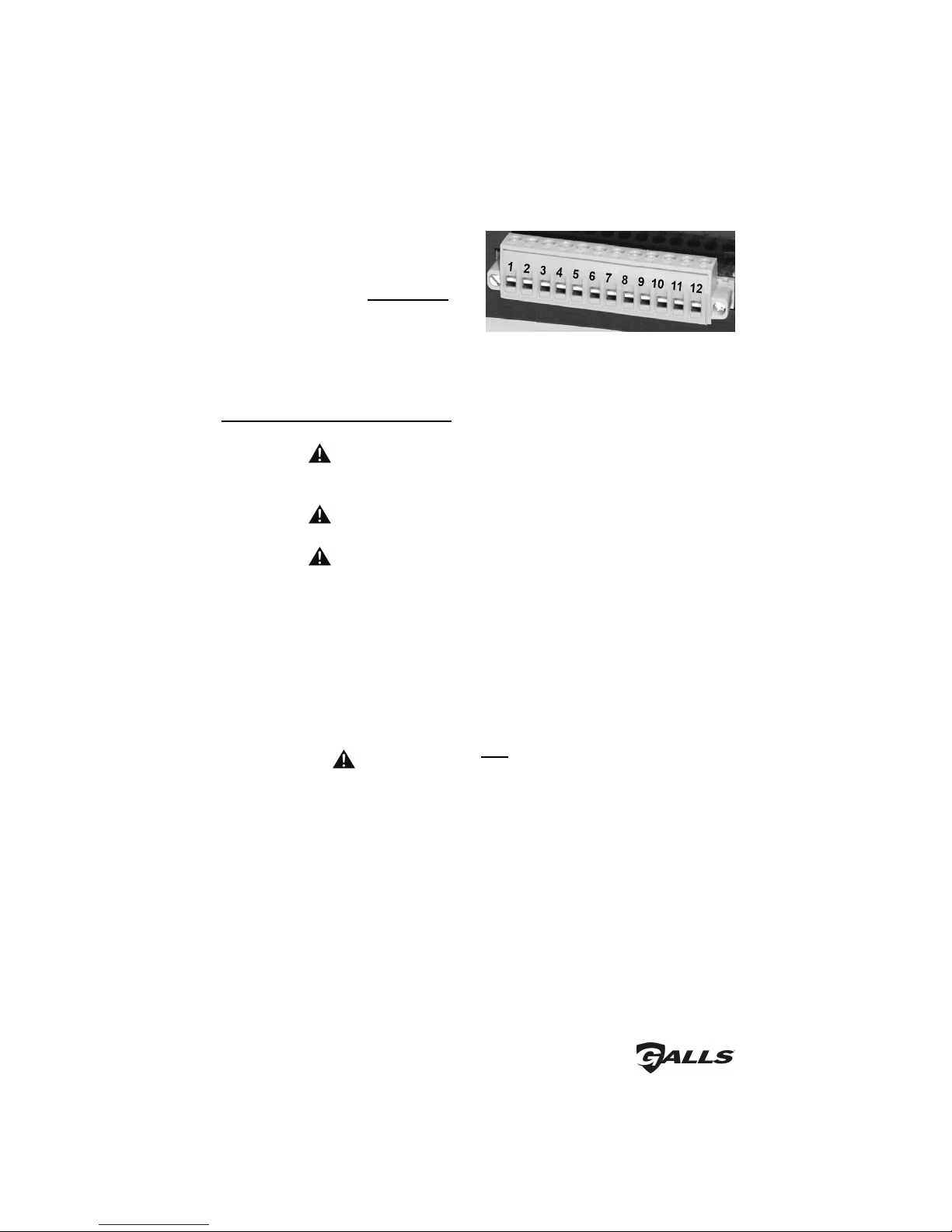
There is a diagnostic LED shaped like a speaker located in the upper right hand
corner of the front panel. This LED will only turn on while a tone is trying to be
generated. It can be used to help identify the siren/speaker status.
Steady - Speaker is connected and operating properly.
Single Flash - Standby ode
Double Flash - Short/Over Current
Triple Flash - Park-Kill Activated
Quad Flash - Improper Voltage (too high or low)
Off - No speaker is connected, or
- The siren is Off, or
- The speaker or wire connection has come loose or is electrically
open
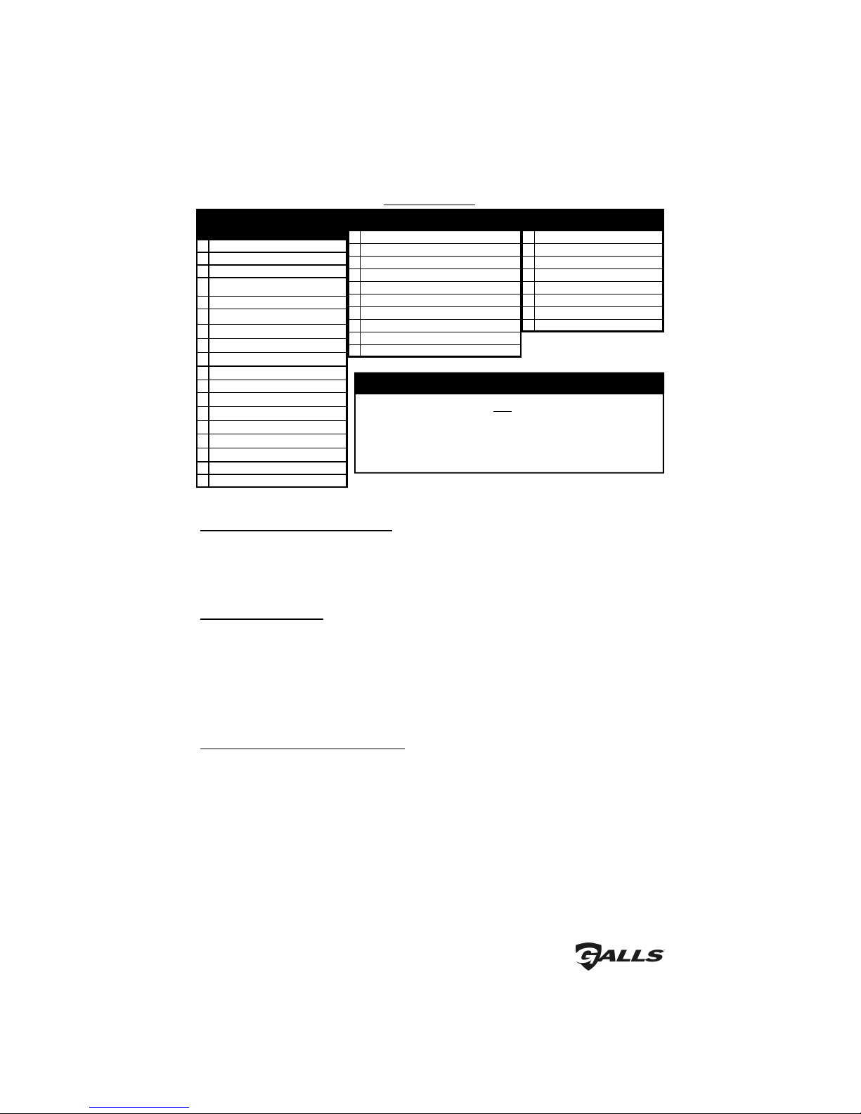
This unit is designed to provide years of reliable service under even the worst
conditions. any times there may appear to be a problem with the unit when the
true problem is in the speaker(s) or improper installation. The following chart shows
typical symptoms and possible causes.
Troubles ooting
Symptom
Possible Cause
Check
No power Connector loose
Siren 20A fuse blown
Loose connection t power source
Check connector
Is power hooked up b ckw rds? Positive ground vehicle?
Is n extern l fuse or circuit bre ker used?
Are the neg tive le ds connected to good ground?
No siren tone - PA
works
No siren tone - No
sound
High volt ge protection
Low volt ge protection
Microphone button stuck
P rk Kill pol rity option set wrong
P rk Kill ctiv ted
B d spe ker or spe ker wiring
The input volt ge must be less th n 16 volts.
The input must be gre ter th n 10V with the siren turned on.
Does microphone button rele se properly?
Is the PK jumper option properly configured?
Does the siren work when P rk Kill input is disconnected?
Check for short.
Check for n open.
No PA PA volume not set properly H ve you tried turning the PA volume control?
Distorted siren sound Spe ker ssembly loose
Intermittent Aux. Input connection
Low or high vehicle volt ge
Is the spe ker bell or tip loose?
Is the Aux. Input connected properly to horn rel y?
Input volt ge must be between 10 & 16 volts while siren is on nd
dr wing full current.
Intermittent siren tone High volt ge protection
Low volt ge protection
Microphone button ctiv tion
Circuit bre ker in supply connection
Shorted spe ker or spe ker wire
Is the vehicle volt ge regul tor working properly?
Is the connector tight on the b ck of the unit? Is there loose
connection on power le d? The input must be gre ter th n
10V with the siren on nd dr wing full current.
Is something lying on the microphone?
Is circuit bre ker used with t le st 50A r ting?
Does the spe ker h ve w ter d m ge, or is wire pinched?
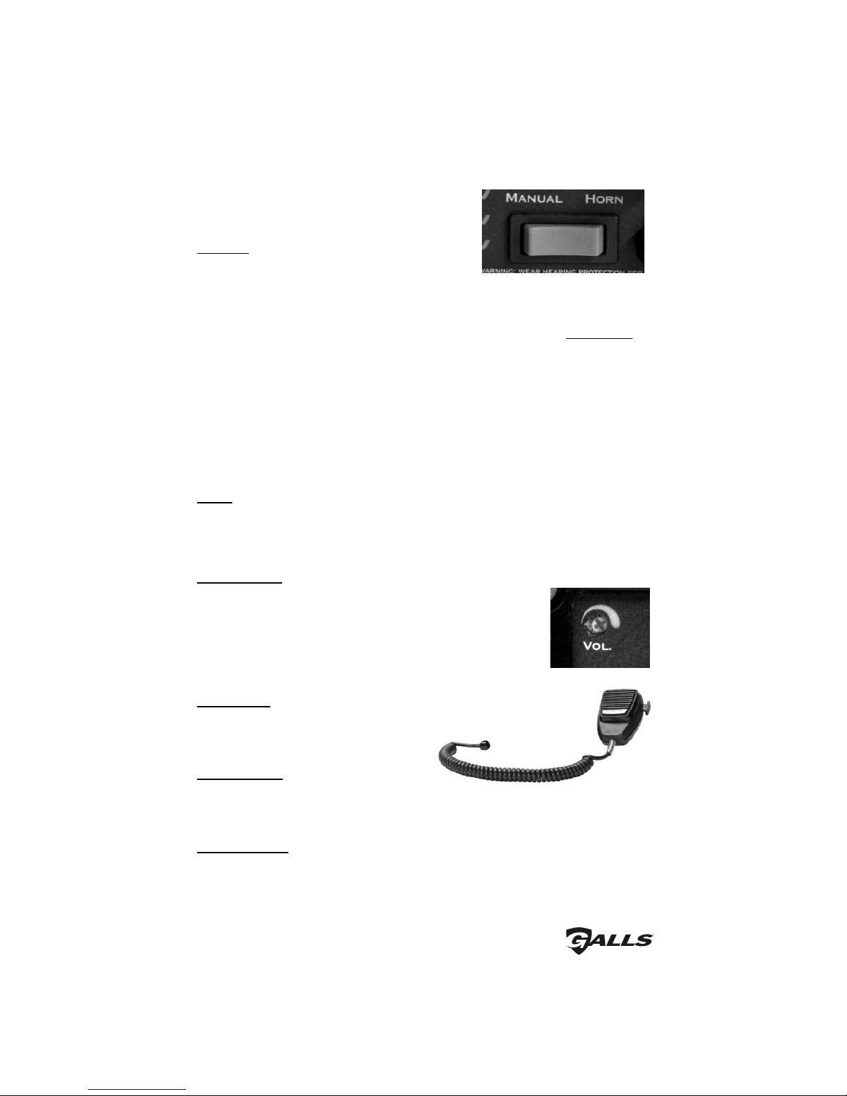
Horn function or
M nu l or Thunder
stuck on
M nu l or Horn push buttons stuck
Aux. Input improperly connected
Aux. Input Pol rity Option set wrong
Does the switch return fully when rele sed?
Is the Aux. Input used nd wired properly?
Is the AUX pol rity jumper option properly configured?
No R dio
Unit not connected to r dio
R dio volume too low
Is the r dio connected properly to the unit?
C n you he r the r dio in the vehicle?
Adjust the R dio volume control
Wrong siren tone Siren tones progr mmed incorrectly? Re-progr m tones/Use System Reset (p ge 5)

-9-
Parts
Service
Part
Description
S30161-18 Siren Top Extrusion
P30234-11-1P Siren Bottom Mounting Pl te
SWH-152
Option l Wiring H rness
P30069-38
Microphone Br cket with Screws
P30056-16
1/4-20 x 3/8" Hex Locking Bolt
P30028-23
20 Amp Automotive Fuse
P30232-1
Noise C ncelling Microphone
P30208-10
Microphone Str in Relief
P30032-8
TIP36CPowerTr nsistor
S30239-11
Rot ry Selector Switch Knob
P30147-44
Mounting Br cket
P30052-40
C se Screws
Specifications
Input Volt ge
10 - 16 VDC (neg tive ground)
Input Current
8.0 Amps @ 13.6 VDC (single 100W spe ker)
16 Amps @ 13.6 VDC (du l 100W spe kers)
St ndby Current
Switch Off/B cklighting Off - Less th n 4 mA
Switch On/B cklighting Off - Less th n 7 mA
Switch Off/B cklighting On - Less th n 40 mA
Switch On/B cklighting On -
≈
44 mA
Audio Frequency
200Hz - 10 kHz + 3db
Output Power
105 WATTS RMS MAX. (15.0 VDC - single 100W spe ker)
200 WATTS RMS MAX. (15.0 VDC - du l 100W spe kers)
Siren Frequency
675Hz - 1633Hz
High Volt ge Protection
16 - 18 VDC will c use siren output to ce se, resumes t norm l volt ge
Short Circuit Current
50 AMPS (supply circuit must be c p ble of supplying this)
Oper ting Temper ture
-22° F to +140°F
Di gnostic Indic tor
LED indic tor provides di gnostic feedb ck
Connections
Det ch ble 12-termin l connector
Size
6" Wide x 4.5" Deep x 2-1/2" High
Shipping Weight
6 lbs.

No Hassle Guarantee
Providing quality products to professionals who
protect and serve the public is our core purpose.
If you aren’t satisfied with a newly purchased item, simply return
it to us so we can repair it, replace it or refund your money.
o Return Merchandise…
Within the first 60 Days:
Ple se cont ct G lls Customer Service Department t (800) 477-7766.
After 60 Days:
Ple se cont ct the m nuf cturer t (585) 226-9025.
If you h ve ny questions concerning this or ny other G lls product, ple se
cont ct our Customer Service Department t (800) 477-7766.
Limited Warranty
Galls warrants this new product to be free from defects in material and workmanship, under
normal use and service, for a period of five (5) years from the date of delivery to the first user-
purchaser.
During this warranty period the obligation of Galls is limited to repairing or replacing, as Galls
may elect, any part or parts of such product which after e amination by Galls is determined to be
defective in material and/or workmanship.
This warranty does not cover labor charges for removal or re-installation of the product. Fuses
and lamps are not covered under this warranty.
This warranty does not e tend to any unit that has been subjected to abuse, misuse, improper
installation, or which has not been adequately maintained, nor to units which have problems
related to service or modification at any facility other than the manufacturer.
THERE ARE NO OTHER WARRANTIES, EXPRESSED OR IMPLIED, INCLUDING BUT NOT
LIMITED TO, ANY IMPLIED WARRANTIES OF MERCHANTABILITY OR FITNESS FOR A
PARTICULAR PURPOSE. IN NO EVENT SHALL GALLS BE LIABLE FOR ANY LOSS OF
PROFITS OR ANY INDIRECT OR CONSEQUENTIAL DAMAGES ARISING OUT OF ANY SUCH
DEFECT IN MATERIALS OR WORKMANSHIP.
This manual suits for next models
1
Table of contents
Other Galls Amplifier manuals