manuals.online logo
Brands
  1. Home
  2. •
  3. Brands
  4. •
  5. GAM
  6. •
  7. Tyre Changer
  8. •
  9. GAM SX4 FOUR Gobo User manual

GAM SX4 FOUR Gobo User manual

Page 1 of 6
Four channel setting switches are on the control box. The MODE switch is the left one and nearest the red LED power
indicator. The right hand switch is the X1 DMX.
Address then X10 and X100
It is powered by 24 volt DC and controlled by DMX512, either from most color scroller power supplies or a standalone power
supply. Once powered, the unit will show a red power LED to indicate the power is on. The unit is also fitted with a green
LED which indicates the status of operation. After it is powered, the unit needs to initialize to find the home position of the
gobos. This takes about 2 seconds during which time the green LED will flash. Once the home sensing is complete the
flashing will stop. If the LED is not lit then DMX is not present. If the LED continues flashing, it means there has been a fault
detecting the sensor and the unit operates but without correct index positioning.
SX4® FOUR & SIX GOBO CHANGER OPERATING INSTRUCTIONS
X1MODE X10
X100
Red Green
 MODE DMXCHANNELS  FUNCTION
 0 0 Standlone:slectonegoboforfocus
 1 1 DMXgoboselectbyfader
 2 2 DMXVgoboselect-speed&position
 3 0 Standalone:speed,direction,timed
 4 0 Standalone:2to6gobos,timed
 5 0 Standalone:continuousrotate,setspeed
 6 1 DMXcontrolledrotationonly
 7 1 DMXcontrolindex/rotateonefader
 8 2 DMXindex/rotateontwofaders
 9 2 16bitindexing/10,000positions
--------------- CAUTION ----------------
When using a DMX device with a discharge lamp such as CDM or an HMI, it's suggested that you separate the power circuit for the discharge
lamp from the DMX control device. When using DMX controlled units such as an Indexing TwinSpin™ or SX4® Gobo Changer or DMX Loop Tray,
the "noise" from the discharge lamp ballast may cause some interference and or damage the electronics. For best results we recommend
providing separate line voltage to the DMX devices and the discharge light fixture.
Page 2 of 6
Set X1 Thumbwheel – This number is for selecting gobo.
Each gobo is individually selected according to the following table.
SELECTIONGOBO DISPLAYED
GOBO DISPLAYED
0 ,1 1 1
2 2 2
3 3 3
4 4 4
5 5 4
6 6 4
7 6 4
8 6 4
9 6 4
MODE 1 OPERATION • MODE SWITCH = 1
MODE 0 OPERATION • MODE SWITCH = 0
DMX gobo selector – one channel operation
Set DMX address on SX4® – This number is the desk control (fader) channel.
Gobo will change at the levels shown in the charts below. Moves at maximum
speed and via the shortest route.
FOUR
100%
76%
255
192 Gobo 4
51%
191
128 Gobo 3
26%
127
64 Gobo 2
0%
63
0Gobo 1
SIX-GOBO CHANGER
SIX-GOBO CHANGER
X1 FOUR-GOBO CHANGER
FOUR-GOBO CHANGER
CHANNEL LEVEL CHANNEL LEVELDMX LEVEL DMX LEVEL SIX
100%
84%
255
215 Gobo 6
67%
214
172 Gobo 5
51%
171
129 Gobo 4
34%
128
86 Gobo 3
18%
85
43 Gobo 2
0%
42
0
Gobo 1
Standalone single gobo select – for focusing
Page 3 of 6
MODE 2 OPERATION • MODE SWITCH = 2
MODE 3 OPERATION • MODE SWITCH = 3
DMX gobo select with direction and speed control – Two channel operation
S e t D M X add r e ss on S X 4
®
– T h i s nu m be r i s t he de s k c on t r o l ( f ade r) c hannel.
C hanne l 1 : G obo w ill c hange a t t he l e v e l s s ho w n i n t he c ha r t s a s pe r M ode 1 .
C hanne l 2 : S e t s s peed and d i r e c t i on o f c hange a s pe r c ha r t be l o w .
CHANNEL LEVEL D M X LEVEL DIRECTION
100 %
76%
25 5
19 2
F a s t counterclockwise
counterclockwise
counterclockwise
counterclockwise
counterclockwise
counterclockwise
counterclockwise
V a r i ab l e s peed l e v e l s
S l o w
51%
19 1
12 8
F a s t cl
cl
o ck w i s e
V a r i ab l e s peed l e v e l s
S l o w o ck w i s e
26%
12 7
6 4
0 %
6 3
0
S ho r t e s t r ou t e s l o w
V a r i ab l e s peed l e v e l s
S ho r t e s t r ou t e f a s t
Standalone operation displays all gobos in sequence
U s e t he X 100 s w i t c h on t he S X 4® t o s e t d i r e c t i on and s peed a s pe r c ha r t.
U s e t he X 10 , X 1 s w i t c h on t he S X 4
®
t o s e t d i s p l a y t i m e o f ea c h gobo .
S e tt i ng t he s e s w i t c he s f r o m 1 t o 99
v a r i e s t he t i m e i n 0 . 1 s e c ond s t ep s
f r o m 0 . 1 s e c ond s t o 9 . 9 s e c ond s.
X 10 0 DIRECTION SPEED
9
8
V ery s l ow
7
6
S l o w
5
4
Med i u m
3
2
c l o ck w i s e
c l o ck w i s e
c l o ck w i s e
c l o ck w i s e
F a s t
1
0
V e ry f a s t
X 1 0 X 1 T IME ( SECS )
0 0 0 . 1
0 1 0 . 1
4 2 4 . 2
5 0 5 . 0
9 8 9 . 8
9 9 9 . 9
FOUR & SIX GOBO CHANGER
FOUR & S I X GOBO CHANGER
Page 4 of 6
Standalone operation for less than maximum patterns – displays each gobo in sequence
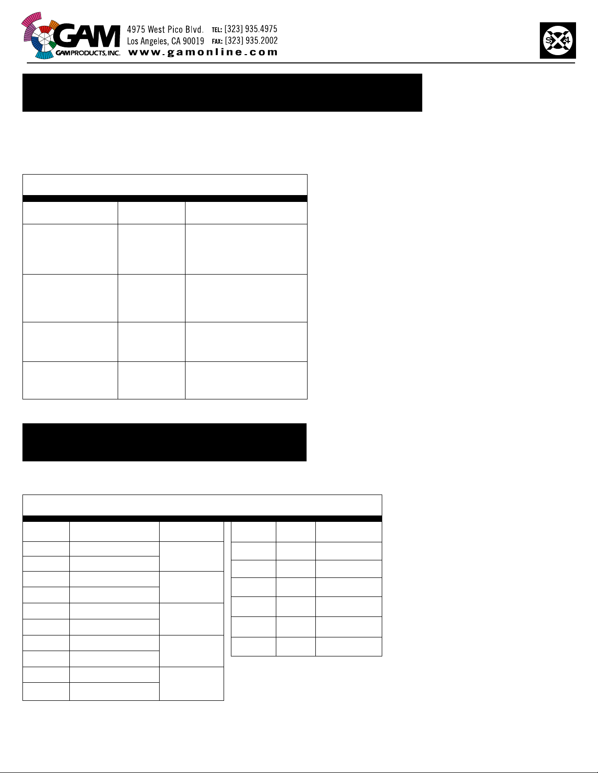
X 1 s w i t c h on S X 4
®
w ill s e t t he d i s p l a y t i m e o f ea c h gobo f r o m 1 t o 10 s e c ond s.
S e t on z e r o f o r 1 s e c ond.
S e t on 9 f o r 10 s e c ond s.
M o v e s be t w een gobo s a t m a x i m u m s peed .
X 100 s w i t c h on S X 4
®
s e l e c t s t he first po s i t i on y ou use in the turret wheel.
X
X
X
X
10 s w i t c h on S X 4
®
s e l e c t s t he last po s i t i on y ou used in the turret wheel.
I f y ou ha v e t h r ee pa tt e r n s, y ou pu t t he m i n po s i t i on s 1 , 2 , 3, t hen pu t t he x 100 s w i t c h.
t o 1 and t he x 10 s w i t c h t o 3 and t he un i t w ill au t o - s e l e c t t ho s e t h r ee po s i t i on s on l y .
I f 100 = 1 and x 10 = 3 t he s e l e c t i on o r de r i s 1 , 2 , 3 , 2 , 1 , e t c.
I f 100 = 2 and x 10 = 5 t he s e l e c t i on o r de r i s 2 , 3 , 4 , 5 , 4 , 3 , 2 , e t c.
I f 100 = 5 and x 10 = 2 t he s e l e c t i on o r de r w ill be 5 , 6 , 1 , 2 , 1 , 6 , 5 , 6 , 1 , 2 e t c .
Standalone operation for continuous rotation
X 100 s e t s d i r e c t i on – s e l e c t 1 f o r counterclockwise or 2 for clockwise rotation.
X 10 , X 1 s e t s s peed o f r o t a t i on – 00 i s s l o w e s t and g r adua ll y i n cr ea s e s i n s peed a s t he.
nu m be r i s i n cr ea s ed up t o a m a x i m u m s peed r ea c hed a t nu m be r 63 .
Rotation only DMX controlled
A pp li e s t o s i ng l e pa tt e r n d i s c e ff e c t s.
S e l e c t D M X c on t r o l c hanne l on S X 4® s w i t c he s X100 , X10 , X1.
S e l e c t ed c hanne l f ade r ope r a t e s s peed and d i r e c t i o n o f r o t a t i on a s pe r c ha r t be l o w .
CHANNEL LEVEL DMX LEVEL DIRECTION
100 %
51%
25 5
12 9
F a s t counterclockwise
V a r i ab l e s peed l e v e l s
S l o w counterclockwise
50% 12 8 S T O PPE D
49%
0 %
12 7
0
S l o w cl
cl
o ck w i s e
V a r i ab l e s peed l e v e l s
F a s t o ck w i s e
MODE 4 OPERATION • MODE SWITCH = 4
MODE 5 OPERATION • MODE SWITCH = 5
MODE 6 OPERATION • MODE SWITCH = 6
Page 5 of 6
DMX single channel linear indexing and rotation control
A pp li e s t o s i ng l e pa tt e r n d i s c e ff e c t s
S e l e c t D M X c on t r o l c hanne l on S X 4® s w i t c he s X 100 , X 10 , X 1
C on t r o l c hanne l f ade r ope r a t e s i nde x / r o t a t e f un c t i on s a s pe r c ha r t be l ow
DMX LEVEL
APPLIES TO SINGLE PATTERN DISC EFFECTS
DIRECTION
DIRECTION
100 %
52%
25 5
13 0
S l o w c l o ck w i s e
V a r i ab l e s peed l e v e l s
C on t i nuou s r o t a t i o n
F a s t c l o ck w i s e
51% 12 9 S T O PPE D
50%
0 %
12 8
0
360 deg r ee s
I nde x i ng t o po s i t i o n
w i t h s ho r t e s t r ou t e
maxi m u m s pee d
0 deg r ee s ( ho m e )
MODE 7 OPERATION • MODE SWITCH = 7
MODE 8 OPERATION • MODE SWITCH
= 8
A pp li e s t o s i ng l e pa tt e r n d i s c e ff e c t s and gobo d i s c s
S e l e c t D M X c on t r o l c hanne l on S X 4® s w i t c he s - X 100 , X 10 , X 1
C on t r o l c hanne l f ade r ha s t w o f un c t i on s
1 . O pe r a t e s a s an i nde x i ng f ade r f r o m z e r o t o 99%
2 . I f s e t a t 100% t hen i t ho l d s t he d i s c i n t o c on t i nuou s r o t a t i on m od e
CHANNEL LEVEL
CHANNEL LEVEL
SETTING CHOICES FOR CHANNEL 1
DMX LEVEL
100 % 25 5 C O N T I NU O U S R O T A TION M O D E
99 %
0 %
25 4
0
359 deg r ee s
V a r i ab l e i nde x po s i t i on s
0 deg r ee s ( ho m e )
DMX TWO channel linear indexing with variable speed rotation
SECOND CHANNEL CONTROLS SPEED
& DIRECTION OF DISC PER CHART WHEN
1ST CHANNEL IS AT 100% CONTINUOUS
ROTATION MODE
SECOND CHANNEL CONTROLS SPEED
& DIRECTION OF DISC PER CHART
WHEN 1ST CHANNEL IS SET FROM 0-9
INDEXING MODE
MODE 9 OPERATION • MODES SWITCH = 9
CHANNEL
LEVEL
CHANNEL
LEVEL
D M X
LEVEL
100 %
51%
25 5
12 9
F a s t counterclockwise
V a r i ab l e s peed l e v e l s
C on t i nuou s r o t a t i o n
S l o w counterclockwise
50% 127 , 12 8 S T O PPE D
DIRECTION
49%
0 %
12 6
0
S l o w c l o ck w i s e
V a r i ab l e s peed l e v e l s
C on t i nuou s r o t a t i o n
F a s t c lock w i s e 0 % 0 Sho r t e s t r ou t e f u ll
s pee d
D M X
LEVEL
100 %
51%
25 5
12 8
F a s t counterclockwise
V a r i ab l e s peed l e v e l s
Indexing
S l o w counterclockwise
DIRECTION
50%
1 %
12 7
1
S l o w c l o ck w i s e
V a r i ab l e s peed l e v e l s
C on t i nuou s r o t a t i o n
F a s t c lock w i s e
S e l e c t D M X c on t r o l c hanne l on S X 4
®
s w i t c he s - X100 , X10 , X1 :
U s e c hanne l 1 f o r w ho l e deg r ee po s i t i on s and c hanne l 2 f o r f i ne a li gn m e nt po s i t i on s be t w een t he s i ng l e deg r ee s e tt i ng s
o f c hanne l 1.
C hanne l 1
C O A R SE P O S I T IO N
C hanne l 2
F I N E P O S I T IO N
0 %
100%
100% = 359 deg r ee s
0 deg r ee
I nde x i n g
0 %
100%
100% = 1 deg r ee
0 deg r ee
F i ne I nde x i n g
Page 6 of 6
DMX TWO channel highly accurate 16 bit linear indexing for all disc types

This manual suits for next models

1

Popular Tyre Changer manuals by other brands

Hofmann monty 3650 Operation manual

Hofmann

Hofmann monty 3650 Operation manual

Sealey TC10A instructions

Sealey

Sealey TC10A instructions

Nussbaum TC 410 instruction manual

Nussbaum

Nussbaum TC 410 instruction manual

pela tools U-2011 manual

pela tools

pela tools U-2011 manual

Hunter TC39 Series Operation instructions

Hunter

Hunter TC39 Series Operation instructions

ATH-Heinl M126 operating instructions

ATH-Heinl

ATH-Heinl M126 operating instructions

Ranger Products R710 Installation and operation manual

Ranger Products

Ranger Products R710 Installation and operation manual

MW TOOLS BT100 manual

MW TOOLS

MW TOOLS BT100 manual

CEMB SM1100 user manual

CEMB

CEMB SM1100 user manual

Fasep RGU 264 E Use and maintenance instructions

Fasep

Fasep RGU 264 E Use and maintenance instructions

Ranger Products R715 Installation and operation manual

Ranger Products

Ranger Products R715 Installation and operation manual

Fasep RASE.2131.T instruction manual

Fasep

Fasep RASE.2131.T instruction manual

ATEK MAKINA KONIG JUNIOR S Instruction booklet

ATEK MAKINA

ATEK MAKINA KONIG JUNIOR S Instruction booklet

Pro-tec TC-512A Installation, operation & maintenance manual

Pro-tec

Pro-tec TC-512A Installation, operation & maintenance manual

John Bean EHP System I Operation instructions

John Bean

John Bean EHP System I Operation instructions

Corghi ARTIGLIO 50 Operator's manual

Corghi

Corghi ARTIGLIO 50 Operator's manual

SICE S 60 Operator's manual

SICE

SICE S 60 Operator's manual

HENNESSY INDUSTRIES Coats 4050A Safety Instructions, Operating Instructions, Installation Instructions, Maintenance Instructions

HENNESSY INDUSTRIES

HENNESSY INDUSTRIES Coats 4050A Safety Instructions, Operating Instructions, Installation Instructions, Maintenance Instructions

manuals.online logo
manuals.online logoBrands
  • About & Mission
  • Contact us
  • Privacy Policy
  • Terms and Conditions

Copyright 2025 Manuals.Online. All Rights Reserved.