Ganz GH Series User manual

Alimentatori interni
Internal power supplies
Alimentation interne
Internes Netzteil
Wewnętrzny transformator
GH SERIE
Manuale di istruzione
Instruction manual
Manuel de instructions
Bedienungsanleitung
Instrukcja obsługi
Leggere attentamente tutte le avvertenze ed istruzioni riportate prima di
procedere al montaggio ed uso dell’accessorio.
Read carefully all instruction and safeguards reported on this manual before
procced on assembling and use of the accessories.
Avant de procéder à l’installation et la mise en service du matériel, merci
de lire attentivement les instruction et indication reportées dans ce manual.
Lesen Sie die Anleitung und die darin enthaltenden Warnungen sorgfältig,
bevor Sie das Gehäuse montieren oder in Betrieb nehmen.
Przed rozpoczęciem montażu i obsługi produktu prosimy o uważne
przeczytanie i stosowanie siędo instrukcji i uwag, zawartych
w poniższym podręczniku.
GH-PS230/24
Trasformatore – Power transformer – Carte d’alimentation – Trafo – Transformator 230Vac /24Vac (230Vca/24Vca)
GH-PS230/12
Alimentatore – Power supply – Carte d’alimentation – Netzteil - Transformator 230Vac/12Vdc (230Vca/12Vcc)
GH-PS24/12
Alimentatore – Power supply – Carte d’alimentation – Netzteil - Transformator 24Vac/12Vdc (24Vca/12Vcc)
Rev: 201204
2
FIG 1
FIG 2
FIG 3
FIG 4
FIG 5
3
Gli alimentatori GH-PS230/24, GH-PS230/12 e GH-PS24/12 sono componenti
destinati all’uso interno delle custodie serie GH GANZ per alimentare le
telecamere ospitate nelle custodie stesse.
LA SERIE DI CUSTODIE GANZ GH, ABBINATE AGLI ALIMENTATORI,
RISPONDE ALLE SEGUENTI NORMATIVE:
EN 60065(1998) (Certificazione CE )
EN 55022(1998)
EN 61000-3-2(1995)
EN 61000-3-2/A1(1998)
EN 61000-3-2/A2(1998)
EN 61000-3-3(1995)
EN 50130-4(1995)
EN 50130-4/A1(1998)
IMPORTANTI AVVISI DI PERICOLO E SICUREZZA
Questo simbolo indica che tensioni pericolose per
l’incolumità delle persone sono presenti all’interno del
prodotto.
Questo simbolo indica che le istruzioni riportate devono
essere seguite scrupolosamente per evitare il rischio di
danneggiamento del prodotto ed/o evitare rischi di diversa
natura ed entità per il personale che maneggia il prodotto.
Prima di procedere all’uso ed installazione del prodotto, si prega di leggere
attentamente e capire completamente tutte le indicazioni e le istruzioni
riportate in questo manuale.
Si prega di prendere nota delle seguenti precauzioni ed avvisi di pericolo per la
salvaguardia di beni e persone:
1. L’uso e l’installazione del prodotto deve essere eseguita da personale
tecnico qualificato e nel rispetto delle leggi previste nel luogo dove viene
utilizzato il prodotto.
2. Usare solo componenti o sottoassiemi indicati in questo manuale ed
originali CBC.
3. Dopo operazioni di manutenzione o riparazione o integrazione del prodotto
con componenti opzionali, procedere ad un test di misurazione che
consenta di verificare la non esposizione di alcuna parte a tensioni di
alimentazione.
4. La destinazione d’uso del prodotto, i metodi di installazione ed i materiali
utilizzati per l’applicazione del prodotto devono rispettare tutte le norme di
sicurezza dei beni e delle persone che lo ospitano e pertanto, la
installazione deve garantire il supporto di almeno 4 volte il peso
complessivo dell’intero complesso di ripresa comprendendo in esso anche
il corpo telecamera/obiettivo.
5. Dopo l’utilizzo di questo manuale, se ne consiglia la custodia per future
necessità e consultazioni durante le operazioni di manutenzione o
modifiche.
DESCRIZIONE DEL PRODOTTO
Gli alimentatori GH-PS230/24, GH-PS230/12 e GH-PS24/12 sono componenti
opzionali che servono ad alimentare le telecamere TVCC montate all’interno delle
custodie GANZ serie GH quando L’alimentazione richiesta dalla telecamera
differisce da quella da fornire in ingresso alla custodia, utilizzata per alimentare il
circuito di riscaldamento della custodia stessa.
Gli alimentatori richiedono e forniscono le seguenti tensioni di ingresso uscita:
GH-PS230/24 ingresso: 230Vca uscita:24Vca/12VA
GH-PS230/12 ingresso: 230Vca uscita:12Vcc/360mA
GH-PS24/12 ingresso: 24Vca uscita: 12Vcc/360mA
APERTURA ED USO DELLA CUSTODIA
Utensili necessari
In aggiunta al set di strumenti ed accessori forniti con la custodia, si consiglia di
tenere a portata di mano i seguenti utensili per operare sulla custodia in modo
rapido ed agevole:
Cacciavite medio a croce
Cacciavite medio a taglio
Cacciavite piccolo a taglio
Chiave a brugola da 5mm
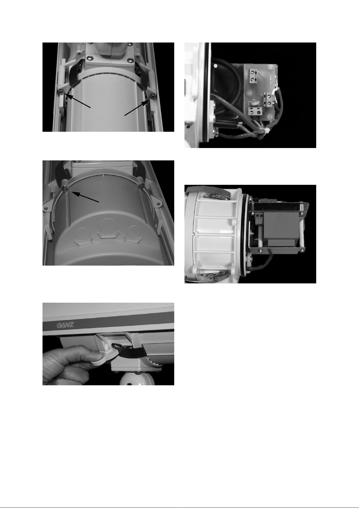
Sgancio o rimozione del tettuccio parasole
ATTENZIONE! I modelli di custodia GH-230KIT e GH-
230, che prevedono una alimentazione a 230Vca,
devono essere sempre provvisti ed installati con
tettuccio parasole anche in interni. Il tutto è richiesto al
fine di evitare l’apertura accidentale del corpo
telecamera anteriore, senza l’ausilio di utensili che
comprovino la volontà di aprire il corpo della custodia
anche sul lato frontale in possibile presenza di
alimentazione.
Per accedere al corpo centrale della custodia è necessario sganciare e ruotare su
uno dei due lati o rimuovere completamente il tettuccio parasole.
Per effettuare questa operazione, rimuovere una o entrambe le viti a brugola
mostrate in figura 1, utilizzando l’attrezzo speciale fornito in confezione.
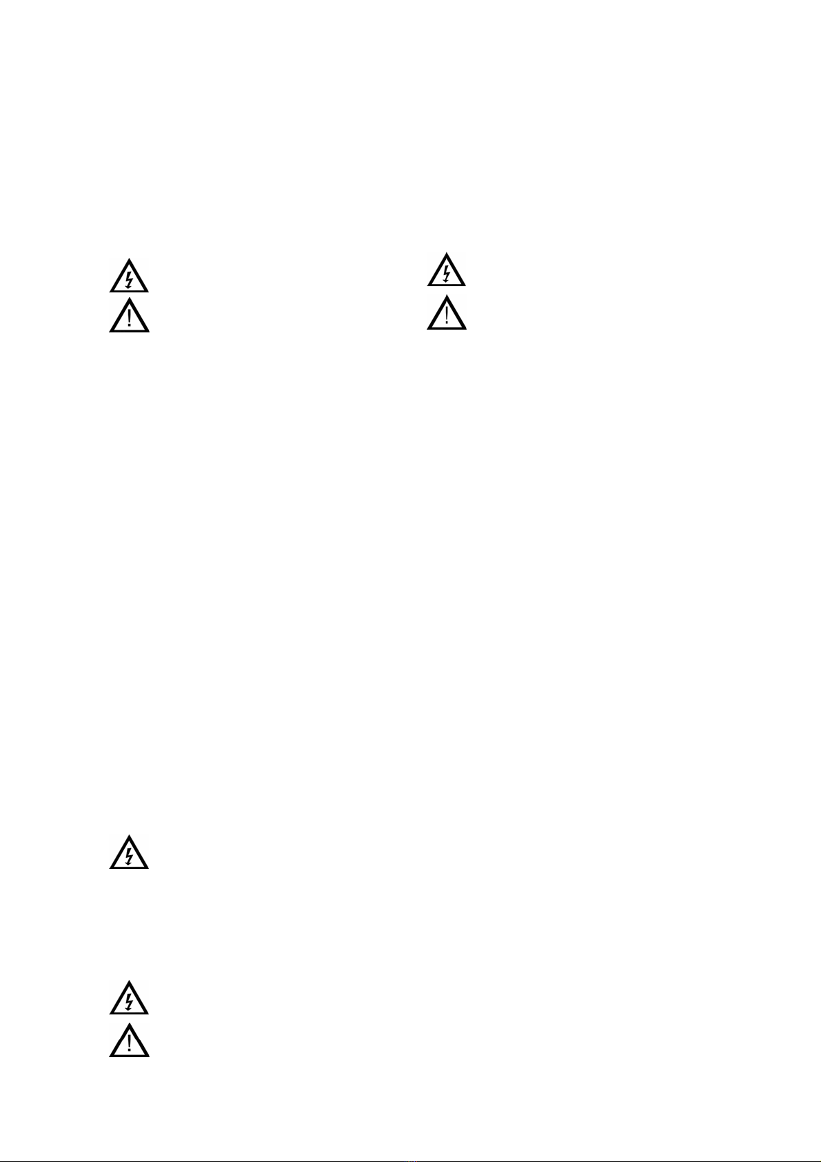
Apertura della parte posteriore della custodia
Attenzione: la parte posteriore della
custodia ospita la scheda di smistamento
alimentazione e morsettiere o
l’alimentatore con presenza anche di alta
tensione: prima di rimuovere questa
parte, assicurarsi di avere tolto tensione
alla linea di alimentazione del complesso
di ripresa.
Per le normative in essere riguardante la sicurezza fisica delle persone, l’accesso
ad aree di prodotti sottoposte ad alta tensione e quindi a rischio degli operatori,
devono essere protette in modo tale che l’accesso sia possibile solo con l’ausilio
di utensili o attrezzi.
Per rimuovere la parte posteriore del corpo, svitare le quattro viti a croce presenti
(vedi figura 2) ed, eventualmente, utilizzare il tettuccio quale appoggio
momentaneo.
CONNESSIONI ELETTRICHE
Fornitura di alimentazione alla telecamera
Collegare i conduttori di alimentazione della telecamera agli appropriati terminali
della scheda del circuito di alimentazione posta nella parte posteriore della
custodia (vedere fig.4 come esempio).
Attenzione: per evitare pericoli all’incolumità delle
persone che svolgono questa operazione ed
all’eventuale danneggiamento del prodotto e di quelli
ospitati, verificare preventivamente che l’alimentazione
fornita dal circuito montato all’interno della custodia sia
coincidente a quello richiesto dalla telecamera: in caso
di incompatibilità, rifornitevi del corretto
trasformatore/alimentatore originale GANZ che
necessitate.
Installazione della scheda interna di alimentazione
Procedere nel seguente modo:
1. Aprire la custodia come indicato in precedenza.
2. Prendere nota del cablaggio esistente. In seguito, scollegare i fili dalle
morsettiere dalla scheda di distribuzione alimentazioni. Rimuovere i
distanziatori in nylon che supportano la scheda.
3. Fissare i distanziali esagonali con le viti, forniti nella confezione,
orientandoli verso l’interno della custodia. (vedere fig.5).
4. Fissare la scheda nuova di alimentazione sui distanziali esagonali,
orientando la morsettiera denominata “VO” verso l’alto (vedere fig.5).
5. Collegare i conduttori di alimentazione della telecamera agli appropriati
morsetti della morsettiera “VO”.
6. Collegare i conduttori della linea principale di alimentazione della custodia
agli appropriati morsetti della morsettiera “230Vac” e quelli relativi al
riscaldatore ai terminali della morsettiera identificata con la scritta “230HT”.
Nel caso non stiate modificando un modello della linea GH-KIT che fornisce il
cablaggio interno già disponibile, potrete utilizzare il passacavo centrale PG11
reso disponibile sul retro della custodia, per farvi transitare un cavo adeguato alle
normative tripolare ed attestare i conduttori sugli appropriati morsetti e morsettiere
come di seguito riportato:
Significato Colore Conduttore Morsettiera
Ingresso alimentazione Blu/Marrone “230Vca”
Alimentazione riscaldatore Bianco “230HT”
Alimentazione telecamera “VO”
In aggiunta, crimpare il conduttore di massa su un terminale rotondo e fissarlo
sull’apposita sede identificata con il segno di terra, tramite una vite M4 fornita.
Fissare il tettuccio parasole
Posizionare il tettuccio nelle sedi appropriate.
Inserire le due viti nelle proprie sedi (o una se del caso) e stringere
appropriatamente.

4
The power supply units GH-PS230/24, GH-PS230/12 and GH-PS24/12 are
components designed and addressed for internal use of GH GANZ housing only,
with the purpose to provide correct power voltage to the camera hosted inside of
the housing.
The GANZ housing series, combined with the internal power supplies,
subjects of this manual, are compliant with the following Standards:
EN 60065 (CE certification for EMC and safety)
EN 55022(1998)
EN 61000-3-2(1995)
EN 61000-3-2/A1(1998)
EN 61000-3-2/A2(1998)
EN 61000-3-3(1995)
EN 50130-4(1995)
EN 50130-4/A1(1998)
IMPORTANT SAFEGUARDS AND WARNINGS
This symbol indicates that dangerous
voltage constituting a risk of electric shock
is present inside of this unit.
This symbol indicates that there are
important instruction that have to be
followed reported in the manual to avoid
risk to damage the products or avoid
hazardous risk to maintenance and
service personnel.
Prior to proceed on installation and operation of the product, please read and
understand carefully all the indication and instruction reported on this manual.
Please take note and observe the following warnings:
1. Installation and servicing have to be done only by qualified personnel and
in compliant with local law.
2. Use only parts or subassembly indicated in this manual and original by
CBC.
3. After maintenance or repair/replacement of parts, please proceed in a
check where should be assured that none of the exposed parts have not
been connected to main power or line circuitry.
4. The installation method and materials have to be safe and should be able
to support minimum 4 times the weight of camera/lens+housing and
bracket weight combined
5. After reading the manual, please preserve it for future needs and use for
servicing and maintenance operation
PRODUCT DESCRIPTION
The GH-PS230/24, GH-PS230/12 and GH-PS24/12 are optional components for
GH housing serie that must be used to provide the correct power supply to the
CCTV camera that you would like to mount inside of the GANZ housing when the
power supply requested by the camera is different from the ones requested by
housing itself, used to provide power to the circuit heating also.
The power supply units require and provide the following voltages:
GH-PS230/24 Input: 230Vca Output: 24Vca/12VA
GH-PS230/12 Input: 230Vca Output: 12Vcc/360mA
GH-PS24/12 Input: 24Vca Output: 12Vcc/360mA
INSTALLATION AND OPERATION
Tools needed
In addition to the ones provided inside of the housing packaging, the following
tools are needed for a proper and fast operation:
Medium Phillips screwdriver
Medium blade screwdriver
Small blade screwdriver
5mm Allen ex
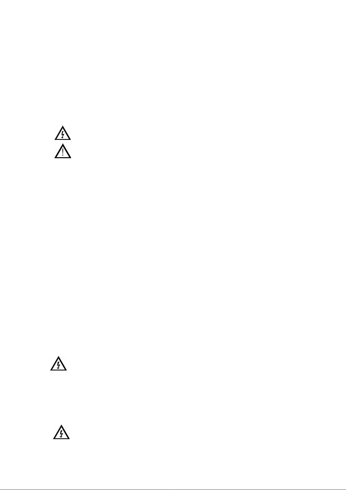
Sunshield removing/pivoting
WARNING! The GH-230KIT and GH-230 need a
power supply at 230Vac. For safety reason, this model
must be provided and installed with sunshield even for
indoor application. This is requested to avoid any
accidental removal operation of the front body part
without the use of any tool that proof the understanding
of operation in progress and the safety
countermeasures needed.
To achieve and open the housing body, the first operation are related to sunshield
removing or pivoting.
The sunshield can be pivoted on both sides alternatively or completely removed
operating by the special Allen ex tool provided into the housing packaging (see
fig.1).
Back side body part removing
WARNING: the back side of the housing
body is destined to host power supply
circuits and terminal strip connection with
presence of high voltage. Before opening
this side, please, switch off the line
source.
For safety regulation, the part of the body hosting power circuits must be
accessed by tool.
To remove this body part, operate on the (4) Phillips screws (see fig.2).
Place the body part removed on the pivoted sunshield.
Electrical Connection
Power supply board installation
Follow these steps:
1. Open the housing like above indicated.
2. Take note of the existing cabling provided. After that, disconnect the cabling
from the power distribution board unscrewing the terminal strips. Remove the
nylon spacer that support the board.
3. By screws provided into the packaging, fix the hexagonal spacer in-yard
oriented (see fig.5).
4. Fix the power supply board on hexagonal spacers, orienting the output “VO”
on upper side.
5. Connect the camera power conductors to the appropriate terminals “VO”.
6. Connect the main power supply input conductors to appropriate “230Vac”
terminals and the ones for heater/thermostat to terminals “230HT”.
In case you have not bought a KIT version of GH housing, the power supply line
have to be provided by a three conductors cable running through the central
PG11 gland inside of the housing: the main power supply conductors have to be
connected to the appropriate terminal strips in the following way:
Meaning Conductors color Terminal strip
MainPower IN Blue/Brown “230Vac”
Out Heater White “230 HT”
Out Camera “VO”
In addition, crimp the ground conductor to a ring terminal and fix it to the point
identified by Ground symbol by the M4 screw provided.
ENCLOSURE ASSEMBLY
Back side body part re-assembly
If this will be the latest operation to complete the housing body closure, insert the
desiccant bag (without plastic protection) inside of the body before to proceed.
Place the back side body part lining up the fixing holes to the screws. Push the
two parts each other until they are properly combined. For better insertion and
good tight against dust or avoid any water leaking, we suggest to spread a thin
layer of syliconic lubricant over the O ring. Then tie the screws, following a cross
fixing order.
Fixing of sunshield
Re-positioning of the sunshield on the holding point(s).
Insert the fixing screw(s) and tie.
5
Les cartes d’alimentation GH-PS230/24, GH-PS230/12 et GH-PS24/12 sont des
composants spécifiquement désignés et conçus pour être utilisés uniquement
avec les caissons GANZ, dans le but de fournir une alimentation correcte à la
caméra qui y est abritée.
La gamme de caissons GANZ, combinée avec les alimentations internes,
sujet de ce manuel, sont compatibles avec les standards suivants :
EN 60065 (Certification CE pour CEM et sécurité)
EN 55022(1998)
EN 61000-3-2(1995)
EN 61000-3-2/A1(1998)
EN 61000-3-2/A2(1998)
EN 61000-3-3(1995)
EN 50130-4(1995)
EN 50130-4/A1(1998)
INFORMATIONS IMPORTANTES DE SECURITE
Ce symbole indique qu’un voltage
dangereux est présent dans l’appareil et
peut constituer un risque de choc
électrique .
Ce symbole indique la présence
d’instructions importantes qui
doivent être suivies pour
éviter d’endommager le matériel
ou éviter des risques hasardeux
sur le personnel de maintenance
et de service.
Avant de procéder à l’installation et la mise en service du matériel, merci de lire
attentivement et de comprendre toutes les instructions et indications reportées
dans ce manuel.
Merci de respecter les informations suivantes :
1. L’installation et la mise en service doivent être effectuées par un personnel
qualifié et doivent être en accord avec les lois locales.
2. N’utiliser que les éléments référencés dans ce manuel et d’origine CBC.
3. Pendant les opérations de maintenant ce ou réparation/remplacement de
pièces, merci de vérifier que les pièces concernées ne sont pas
connectées à l’alimentation générale
4. L’installation ainsi que le matériel doivent être capables de supporter au
minimum 4 fois le poids combiné de camera/objectif + caisson + support
5. Après lecture du manuel, merci de le conserver pour vos besoins futurs et
la maintenance.
DESCRIPTION DU PRODUIT
Les GH-PS230/24, GH-PS230/12 et GH-PS24/12 sont des composants
optionnels pour la gamme de caissons GH qui doivent être utilisés pour fournir
une alimentation correcte aux caméras CCTV que vous voudrez monter dans les
caissons GANZ. Utilisez les lorsque l’alimentation requise par la caméra est
différente de celle fournie par le caisson lui même. Ces alimentations fournissent
également l’alimentation du circuit de chauffage.
Les alimentations demandent et fournissent les voltages suivants:
GH-PS230/24 Entrée : 230Vca Sortie : 24Vca/12VA
GH-PS230/12 Entrée : 230Vca Sortie : 12Vcc/360mA
GH-PS24/12 Entrée : 24Vca Sortie : 12Vcc/360mA
INSTALLATION
Outils requis
En plus de ceux livrés avec le matériel les outils suivants sont nécessaires pour
une installation propre et rapide :
Tournevis cruciforme moyen
Tournevis plat moyen
Tournevis plat de petite taille
Clé Allen 5mm
Dépose et pivot du pare soleil
ATTENTION !Le GH-230KIT et le GH-230 sont
alimentés en 230Vac. Pour des raisons de sécurité,
ces modèles doivent être fournis et installés avec le
pare-soleil même pour les utilsation en intérieur. Cela
pour éviter tout accident lors d’une opération de
démontage de la partie avant. L’utilisation d’outils
(nécessaires pour la dépose du pare-soleil) garantit la
bonne compréhension de la procédure et des mesures
de sécurité à observer.
Afin d’ouvrir le corps du caisson, la première opération a effectuer est la dépose
du pare-soleil.
Ce dernier peut également être pivoté des deux côtés du caissons ou être
complètement enlevé en utilisant la clé Allen fournit dans l’emballage (voir fig.1)
Dépose de la partie arrière
ATTENTION : la partie arrière du caisson
est destinée à accueillir les circuits
d’alimentation ainsi que les borniers à
connections rapides, présence d’un
voltage important. Avant ouverture merci
de couper l’alimentation.
Par mesure de sécurité, la partie accueillant les circuits d’alimentation ne peut
être démontée qu’en utilisant l’outil adequat.
Pour déposer la partie arrière, dévisser les 4 vis à l’aide du tournevis cruciforme
(voir fig.2)
Placer la pièce sur le pare-soleil préalablement pivoté.
Connexion électrique
Installation de la carte d’alimentation
Suivre les étapes suivantes :
1. Ouvrir le caisson comme indiqué ci-dessus.
2. Merci de prendre en note le shema du câblage installé. Déconnecter ensuite
les câbles de la carte d’alimentation. Enlever l’écarteur en nylon qui soutient
la carte.
3. A l’aide des vis fournies fixer l’écarteur hexagonal (voir fig.5)
4. Fixer la carte d’alimentation sur l’écarteur hexagonal en orientant la sortie
“VO” vers le haut (voir fig.6).
5. Connecter les câbles d’alimentation de la caméra aux terminaux appropriés
“VO”.
6 Connecter l’entrée de l’alimentation principale aux terminaux appropriés
“230Vac” et connecter les câbles chauffage/thermostat au terminal “230HT”
Dans le cas où vous n’auriez pas acheté la version Kit des caissons GH, Le câble
d’alimentation doit être composé de 3 brins conducteurs et courir au travers du
PG11 central dans le caisson. L’alimentation principale doit être connectée aux
bornes appropriées en tenant compte des informations suivantes :
Fonction couleur Connecteurs
Alimentation IN Bleu/marron “230Vac”
Sortie chauffage Blanc “230 HT”
Sortie caméra “VO”
De plus, fixer la terre sur le point identifié par le symbole de terre à l’aide de la vis
M4
FERMETURE DE L’ENSEMBLE
Replacer la partie arrière.
Avant fermeture définitive n’oubliez pas de placer le sachet déshumidifiant (sans
sa protection plastique) à l’intérieur du caisson.
Placer la partie arrière du caisson en alignant parfaitement les trous et les vis.
Pour une meilleure étanchéité, nous suggérons de vaporiser une fine couche de
lubrifiant siliconé sur le pourtour. Fixer ensuite les vis.
Fixer le pare-soleil
Repositionner le pare-soleil sur son support.
Fixer l’ensemble à l’aide des vis prévues à cet effet.

6
Die Netzteile der Gehäuse GH-PS230/24, GH-PS230/12 und GH-PS24/12 sind
speziell für die GH-Ganz Gehäuseserie entwickelt worden, um eine korrekte
Spannungsversorgung der eingebauten Kamera zu gewährleisten.
Die Ganz Gehäuseserie kombiniert mit den Netzteilen erfüllen die folgenden
Standards:
EN 60065 (CE Zertifikation für EMC und Sicherheit)
EN 55022 (1998)
EN 61000-3-2 (1995)
EN 61000-3-2/A1 (1998)
EN 61000-3-2/A2 (1998)
EN 61000-3-3 (1995)
EN 50130-4 (1995)
EN 50130-4/A1 (1998)
Wichtige Sicherheitshinweise
Das Symbol zeigt an, dass die Gefahr eines
elektrischen Schlages im Gehäuseinneren besteht.
Das Symbol zeigt an, dass die Anweisungen in der
Anleitung zu befolgen sind, um eine Beschädigung der
Produkte oder Verletzung von Servicepersonal durch
elektrischen Schlag zu verhindern.
Bevor Sie das Produkt in Betrieb nehmen oder
installieren lesen Sie sich zuerst die Anleitung
sorgfältig durch.
Bitte befolgen Sie folgende Hinweise:
1. Installation und Service sind nur von geeignetem Fachpersonal
durchzuführen
2. Benutzen Sie nur Geräte und Zubehör, die in dieser Anleitung aufgeführt
sind oder Zubehör von CBC sind.
3. Die Befestigungskonstruktion sollte bis zu ein Vierfaches des gesamten
Eigengewichtes der Einheit aushalten.
4. Heben Sie die Anleitung für spätere Verwendungen gut auf.
Produktbeschreibung
Die Auswahl der Netzteile GH-PS230/24, GH-PS230/12 und GH-PS24/12 richtet
sich nach der Kamera, die in das Ganz Gehäuse eingebaut wird. Dadurch wird
eine korrekte Spannungsversorgung der eingesetzten Komponenten
gewährleistet, zugleich wird auch die Heizung des Gehäuses an das Netzteil
angeschlossen.
Die Netzteile sind in folgenden Ausführungen erhältlich:
GH-PS230/24 Eingang: 230 VAC Ausgang: 24 VAC/12VA
GH-PS230/12 Eingang: 230 VAC Ausgang: 12 VDC/360 mA
GH-PS24/12 Eingang: 24 VAC Ausgang: 12 VDC/360 mA
Installation und Bedienung
Benötigtes Werkzeug
Zusätzlich zum beigepackten Zubehör wird folgendes Werkzeug benötigt:
Medium Phillips Schraubenzieher
Medium Schlitzschraubenzieher
Kleiner Schlitzschraubenzieher
5mm Inbusschlüssel
Sonnenschutz abziehen/abhängen
ACHTUNG! Das GH-230 Kit und das GH-230
benötigen ein 230 VAC Netzteil. Zur Sicherheit mußdas
Gehäuse mit Sonnenschutz auch für Innenanwendung
installiert werden. Dadurch wird verhindert, dass das
Gehäuse unbefugt ohne Verwendung von Werkzeug
geöffnet werden kann.
Um das Gehäuse zu öffnen, muß erst der
Sonnenschutz abgenommen oder aufgeklappt werden.
Der Sonnenschutz kann zu beiden Seiten weggeklappt
werden oder mit dem beigepackten Inbusschlüssel
gelöst und abgenommen werden (s. Abb.1).
Rückseite abnehmen
ACHTUNG! Die Gehäuserückseite dient zum Schutz
des Netzteils und des Anschlussterminals für 230 V
Spannung. Vor Öffnen des Gehäuses ist der Strom
abzuschalten.
Zur Sicherheit muß zum Lösen des Anschlussblocks
geeignetes Werkzeug verwendet werden.
Zum Lösen des Anschlussblocks müssen die vier
Phillipsschrauben gelöst werden (s. Abb.2).
Legen Sie den gelösten Anschlussblock auf das aufgeklappte Sonnendach.
Elektrischer Anschluß
Netzanschlußboard installieren
Folgen Sie der Anweisung:
1. öffnen Sie das Gehäuse wie oben beschrieben
2. Beachten Sie bereits vorhandene Verbindungen. Lösen Sie die Verbindung
zum Anschlußboard, indem Sie das Anschlussterminal losschrauben.
Entfernen Sie den Nylonfaden.
3. Befestigen Sie die beigepackte Sechskantschraube wie in Abb. 5
beschrieben.
4. Befestigen Sie das Netztei auf den Abstandhaltern mit der Bezeichnug
VO nach oben (s. Abb. 6).
5. Verbinden Sie die Kamera mit den Anschlussblöcken VO
6. Verbinden Sie den Eingang des Netzteils mit dem Anschlussblock mit
der Bezeichnung 230 VAC und die Heizung/Thermostat mit dem
Anschlussblock mit der Bezeichnung 230 HT.
Wenn Sie keine KIT Ausführung erworben haben führen Sie ein dreiadriges Kabel
durch die PG-Verschraubung PG11 ins Innere des Gehäuses. Die
Stromversorgung wird wie folgt am Anschlussterminal angeschlossen:
Bedeutung Farbe Terminal
Main Power Eingang blau/braun 230 VAC
Heizung Ausgang weiß 230 HAT
Kamera Ausgang VO
Schließen Sie zusätzlich die Erdung am Gehäuse mit der Schraube M4 an.
Gehäuse Zusammenbau
Befestigung der Rückseite
Sollte dieses der letzte Schritt zum Zusammenbau des Gehäuses sein, legen Sie
den Siliconbeutel ein, bevor Sie das Gehäuse zuschrauben.
Legen Sie die Rückseite auf die Verschraubungen. Sorgen Sie für eine gute
Verbindung zum Gehäuse, um das Eindringen von Staub und Feuchtigkeit zu
vermeiden. Wir empfehlen die Verwendung von etwas Silikon, um eine bessere
Dichtigkeit zu erzielen. Ziehen Sie die Schrauben fest an.
Sonnendach befestigen
Richten Sie das Sonnendach auf die Halterung aus und befestigen Sie es
mit den Schrauben.

7

8
CBC (EUROPE) Ltd.
Sede Secondaria di Milano
via E. Majorana,2
20054 - Nova Milanese (MI)
Italia
Tel. +39-0362-365079
Fax +039-0362-40012
CBC (EUROPE) Ltd.
7/8 Garrick Industrial Centre
Irwing Way
GB London NW9, 6AQ
Tel. +44-(0)208-732-3312
Fax +44-(0)208-202-3387
www.cbceurope.com
CBC (EUROPE) Ltd.
Paris Branch Office
1, Avenue des Marguerites
ZAC des Petits Carreaux
94389 Bonneuil sur Marnes
France
Tel.+33-(0)1-43-99-04-24
Fax +33-(0)1-43-99-59-06
CBC (Deutschland)GmbH.
Hansaallee, 191
40549 - Dusseldorf
Germany
Tel. +49-(0)211-530670
Fax +49-(0)211- 53067180
www.cbc.de
CBC (Poland) Sp.zo.o
Ul G. Morcinka,5 Paw6
01-496 Warszawa
Poland
Tel. +48-(0)22-638-4440
Fax +48-(0)22-638-4541
This manual suits for next models
3
Table of contents
Languages:
Popular Power Supply manuals by other brands


NETGEAR
NETGEAR RPS4000v2 Hardware installation guide

TDK-Lambda
TDK-Lambda RWS 1500B Series instruction manual

Heath
Heath Heathkit IP-32 Schematic diagram

Cisco
Cisco PWR/7-DC Series Installation and replacement instructions

SonicWALL
SonicWALL NSA 2650 installation and replacement

COUGAR
COUGAR 80 PLUS VTC400 manual


