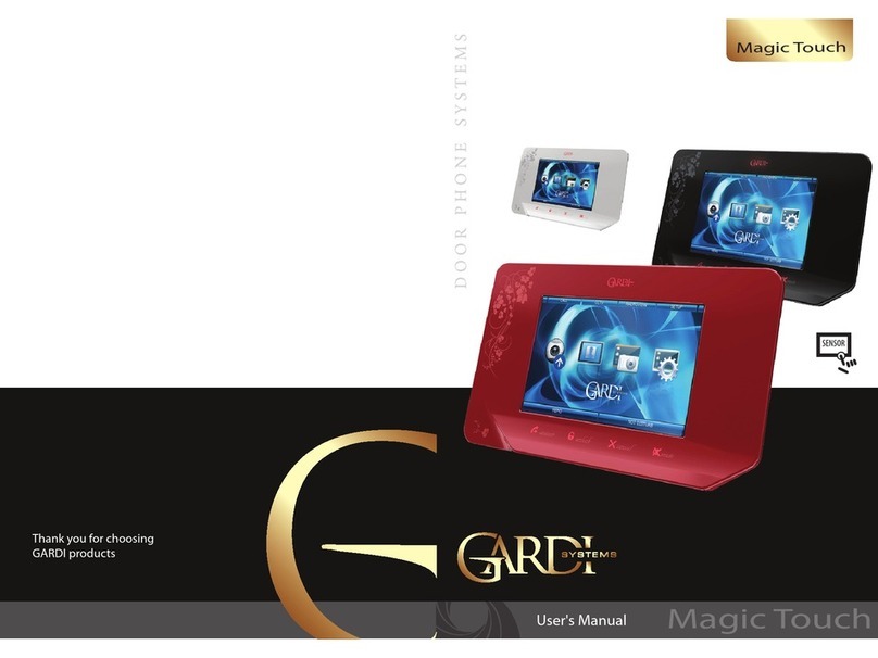
Gardi Systems STYLE User manual

STYLE
STYLE
User's Manual
Thank you for choosing
GRD products

STYLE
User's manual 21
Package
Monitor – 1pc.
Wall mounting bracket with screws– 1pc.
Power supply – 1pc.
Door panel cords – 2pcs.
Sub monitor cord – 1pc.
User's manual – 1pc.
1
4
3
2
1. Display
2. Speaker
3. „Answer/ Intercom/ Call redirection/ Loudspeak” button
4. „View/ Microphone mute/Another monitor listen” button
5. „Open lock” button
6. „Ok/ End call/ Exit menu”button
7. Microphone
8. „Menu” button
9. „Left” button
10. „Right” button
11. Power indicator
Keys
6
5
7
8910
11
Characteristics:
• up to 4 monitors in one system
• 2 door panels connection
• multilingual OSD menu, volume, contrast, brightness and color
tuning
• Incoming calls redirection between monitors in the system
• 7 inch screen
• 12 polyphonic melodies
• Door lock control through the panel or directly from the monitor
• Sensor keyboard
• „Do not disturb” function
Specication:
Display 7" LCD display
Resolution 800х480 (480 TV-lines)
Power 100-240V AC (50-60 Hz)
Power adaptor 14.5V, 1.0 A
Power Consumption 15 W, 1.5 W in standby mode
Door Panels system 4-wires
Video signal system Analog, PAL system
Dimensions 210mm(W)> х 160mm(H) х (T)22mm

STYLE
User’s manual 43
STYLE (ROOM 1)
Door panel 1
Lock 1
Wiring diagram:
Two door panels and two locks connection to the Style monitors system
OK
PWR1
GND
AD1
VD1
KEY1
PWR2
GND
AD2
VD2
KEY2
DATA
AD-1
VD-1
GND
GND
+V
B
G
A
V
D/O
D/O
Door panel 2
Lock 2
B
G
A
V
D/O
D/O
Input 1
Input 2
Input 3
Power adaptor
~ 230V / +14.5V
12V
12V
Keys:
GND - Ground (black wire)
AD - Audio (blue wire)
VD - Video (yellow wire)
PWR - Power (red wire)
DATA - Data (green wire)
KEY - Open lock active signal +12V
(brown wire)
Input 2 and Input 3 are multifunctional, you can conect door panel or camera on this inputs. Camera can be
connected to VD - video and GND - ground wire. Choose the right device you use in settings menu.
DATA
AD-1
VD-1
GND
Input 3
STYLE (ROOM 2)
DATA
AD-1
VD-1
GND
Input 3
STYLE (ROOM 3)
DATA
AD-1
VD-1
GND
Input 3
STYLE (ROOM 4)
Installation instructions
A) Cable connection
1. Connect the monitor to the camera according to the wiring diagram.
2. Carefully insert the wires to the terminal, taking care that the 2 bare wires do not touch.
B) Installation height
Recommended installation height is approximately 140cm for monitor unit and 150cm
for outdoor camera.
C) Installation of the monitor
1. Fix the wall mounting bracket in the best place by using screws and plugs.
2. Carefully place the indoor monitor against the bracket and gently push down the
monitor so that the pins on the bracket engage in the slots on the rear of the monitor.
Cable recommendations:
If cable length between monitor and door panel not more than 30m then you can use
4-wire or 6-wire cable with 0,75 sq.mm. area of one wire. If this length exceeds 30m then
you should use coaxial cable for video (for example RG69), all other connections 4-wire or
6-wire cable can be used.
ATTENTION!
Depending on monitor position in the system (If more then one monitor is used), right
intercom address should be set for every monitor. Main monitor (all cameras and door
panels are conected to the main monitor) intrcom address should be set ROOM1.
Additional monitors ROOM2, ROOM3 and ROOM4 intercom adresses should be used.
If there is only one monitor in the system, then intrcom address should be set ROOM1.
Attention!
Don't connect powerful devices (such as locks and CCD cameras with infrared backlight)
directly to the power supply of door camera. It can cause damage to the monitor with
no warranty providing. You should use external power supply for such powerful devices.
Maximum current for door panel power is 300mA.

STYLE
User's manual 65
OK
OK
Incoming calls answer
When a visitor prsses door panel buttton, all the indoor monitors will chime simultane-
ously. The screen will show “PLEASE TAKE UP”, left upper angle of the screen will show the
image which door panel have been pressed (DOOR1 or DOOR2).
Press button to talk with the visitor (talk time is 60 seconds). If you want to unlock
the door for the visitor during conversation, press button.
DOOR1 UNLOCKED or DOOR 2 UNLOCKED will be shown on the screen. The unlock delay
time is 3 seconds. To end current call before 60 seconds, press button.
Talking volume adjust
When you talk with the visitor or when you make broadcast, you can adjust talking
volume by pressing or buton, to make volume lower or higher.
If you want to mute the microphone, then press and hold button for two seconds,
until “MUTE” sign will appear on the screen. To turn the microphone on, press and hold
button in the same way.
Brightness / color / contrast adjust
This settings can be made only during viewing or talking with the visitor.
The operations are as below:
In any above mode press and hold or button for 2 seconds to adjust
BRIGHTNESS rst. Short press or button to adjust, then press button
to adjust COLOR and then CONTRAST.
Image format convertation 16 : 9 or 4 : 3
Default image format is 16:9.
Sometimes, when you view images, CCTV cameras or when you talk with the visitor, you
can see the images are at. You can convert image format from 16:9 to 4:3 by pressing and
hold button for 2 seconds, then the image will be converted to 4:3 format.
Press and hold this button again then the image will be converted back to 16:9 from 4:3.
Door panels and CCTV cameras viewing
Press button to view DOOR1 image. Press button again to view DOOR2 image
The switching time is 1.8 seconds. Press button to end viewing at any time.
Note: when you are viewing images, if a call is coming from the door panel, the visitor call
will be prior to viwing function. Press button to answer the call. When you nished
talking, press button.
OK
Unlocking door while viewing
Some time, when you are talking with DOOR1, you will see the sign on the screen “SOMEONE IS VISITING DOOR 2”.
That means another person is pressing DOOR2, but you have no chance to talk with the person at DOOR2. So you
have to press button to hang up the phone of DOOR1. Press button to view who is visiting, then press
and hold button for 2 seconds to talk with the visitor, the screen will show “PLEASE TALK”. If you want to
unlock the door for this visitor, press button. DOOR2 UNLOCKED will be shown on the screen, the unlock
delay time is 3 seconds.
Call transfer between monitors
You can transfer your call to any monitor in the system while you are talking to the visitor. If you want to transfer
the call for all monitors, then press button. Press button to answer the call on another montor.
Internal calls among monitors
If you want to make intercom request for all monitors, shortly press button in standby mode. All the indoor
monitors will chime simulteniously, the screen in your room will show “INTERCOM REQUEST”. The screen in
other rooms will show “PLEASE TAKE UP”. Anyone can press button to talk to each other.
If you want to talk with someone privately, you may select any one of other rooms and choose its number on
your screen. Only this monitor will chime and you can start conversation by pressing button on the target
monitor.
If a call is coming from the door panel, “PLEASE TAKE UP” will be shown on the screen. Press button to
answer the call. When you will nish conversation, press button.
Broadcast function
This function allows you to broadcast information for all monitors in your house. To make broadcast announce-
ment, press and hold button for 2 seconds. The monitor in your room will show “BROADCAST
REQUEST”. The monitors in other rooms will show “BROADCASTING”. Now you can make broadcast announce-
ment. Press button to end broadcast request.
Other monitors listening
This function is active only if you have not less than 2 monitors. To activate listening of another monitor, press and
hold button for two secons, then choose the number of the room you want to listen and press to
activate listening. Screen of your monitor will show “LISTENING TO OTHER”. Listeining time is 8 hours, but the
screen will be o in 5 seconds.
The being monitored monitor screen will show ”LISTENED BY OTHER”.
Note: CAN BE MONITORED function should be enabled in SYSTEM SETTINGS of the target monitor. If you want to
deny listening of your monitor from another monitors, disable CAN BE MONITORED function in the SYSTEM
SETTINGS menu of your monitor.
OK
OK
OK

LANGUAGE English or Russian language can be used.
CHIME TIME Length of the call melody in seconds, can be set as: 10 S/20 S/30S/40 S/50 S/ 60 S.
CHIME VOLUME Volume of the incoming call melody, can be set as: 01/02/03/04/05/06/07/08/ 09/10
DO NOT DISTURB Turns o incoming call melody, can be ENABLE or DISABLE.
CAN BE MONIORED Alows other monitors to listen if ENABLE or refuses monitor listen if DISABLE.
ADDRESS Set up the address of the current monitor in the system.
DOOR1 RING TYPE Chooses the melody for the rst dooк panel.
DOOR2 RING TYPE Chooses the melody for the second dooк panel.
INTERCOM RING TYPE Chooses the melody for the intercom call.
PORT2 STATE Denes the status of the Input 2 plug: can be set as DOOR2 (Door panel)/
CCTV1(Camera1)/CCTV2(Camera2), depends on the device connected to the Input 2.
PORT3 STATE Denes the status of the Input 3 plug: can be set as MONITOR (Additional monitor in the
system)/ CCTV1(Camera1)/CCTV2(Camera2), depends on the device connected to the Input 3.
RESTORE DEFAULT Restores all the factory settings.
STYLE
User's manual 87
System settings
Press and hold button for two seconds to enter SYSTEM SETTINGS:
Press or button to move up and down through the settings. Press
button to activate current setting and or button to change
current setting. Then press button one more time to conrm your choise.
Press button to exit system settings any time you want.
System settings consists of two pages. To go to the second page of the system settings,
move the frame to the NEXT MENU by or button and enter it by
button.
To come back to the rst page of the system settings, move the frame to the PRE MENU
by or button and enter it by button.
Monitor listening time 8 hours
8 hours
1 minute
2 minutes
10 seconds
Door panel view time
Cameras view time
Maximum call length time
Minimum call length time
SYSTEM SETTINGS
NEXT MENU
LANGUAGE ENGLISH
CHIME TIME 10 S
CHIME VOLUME 07
DO NOT DISTURB DISABLE
CAN BE MONITORED ENABLE
ADDRESS ROOM1
SYSTEM SETTINGS
GRD V1.22
PRE MENU
DOOR 1 RING TYPE 02
DOOR 1 RING TYPE 03
INTERCOM RING TYPE 04
PORT 2 STATE CCTV1
PORT 3 STATE MONITOR
RESTORE DEFAULT ENTER
OK
Timings

Index
Package..................................................................................................................................................................................................1
Keys..........................................................................................................................................................................................................1
Characteristics................................................................................................................................................................................2
Specication...................................................................................................................................................................................2
Installation instructions..............................................................................................................................................................3
Wiring diagram..............................................................................................................................................................................4
Incoming calls answer.................................................................................................................................................................5
Talking volume adjust.................................................................................................................................................................5
Brightnes/Contrast/Cololr adjust............................................................................................................................................5
Image format convertation 16:9 or 4:3................................................................................................................................ 5
Door panels and CCTV cameras viewing.............................................................................................................................5
Unlocking door while viewing..............................................................................................................................................6
Call transfer between monitors............................................................................................................................................6
Internal calls among monitors.....................................................................................................................................................6
Broadcast function.......................................................................................................................................................................6
Other monitors listening..................................................................................................................................................................6
System settings..............................................................................................................................................................................7
Timings.............................................................................................................................................................................................8
Address setting..............................................................................................................................................................................9
Safety instructions........................................................................................................................................................................9
Warranty...........................................................................................................................................................................................9
STYLE
User's manual 109
Address setting
Before starting to work with the monitor, you should correctly set device ADDRESS. To set
device ADDRESS, enter system settings by press and hold buton for two seconds in
standby mode.
Then go to the ADDRESS setting, using or button. After that, shortly push
button to activate address setting and use or button to choose
correct address. Then press button to conrm address setting.
Set ROOM 1 if you have only one monitor in the system or if it is a monitor which all the door
panels and cameras connected.
Set ROOM 2, ROOM 3 or ROOM 4 if there is no door panels or cameras connected to this
monitor. Two monitors in one system can't have the same address at the same time!
Safety Instructions
1. Do not install near other electronic equipment such as computers, TV, video recorder as
this may cause radiated interference to the unit.
2. Do not disassemble the unit.
3. Do not spray water on the indoor unit. Do not keep the outdoor unit where it will be
exposed to extreme moisture.
4. Do not overload mains wall outlets or extension cords.
5. Do not drop or shock the unit, dropping can result in failure to operate. Circuit boards can
crack and may not survive the impact.
6. Remove the power cord from the wall socket when unit is not used for long periods
7. Do not place any naked ames (e.g. lighted candles) on the apparatus.
8. Do not place objects lled with water (e.g. vases) on the apparatus.
9. Do not cover the ventilation holes with clothing, paper, curtains etc.
10. Keep minimum distance 5cm around the apparatus for sucient ventilation.
11. This apparatus is designed for middle climates. Do not use in high humidity, dusty or
dirty areas. The electronics may be contaminated.
12. To disconnect or isolate the unit, switch o at the socket or remove plug from wall socket.
Please ensure the plug and socket is easily accessible.
13. Do not store in hot or cold areas. Extreme hot or cold temperatures can shorten the life of
electronic devices and can distort/melt certain plastics or may cause malfunction.
14. Do not use harsh chemicals, cleaning solvents or strong detergents. To clean, wipe with a
damp cloth from time to time.
Warranty
Warranty period is 12 months from purchaseing.
Warranty void if unit was damaged by the fault of the custumer.
Warranty void if the sticker on the backside of the unit was broken.
Life time of the unit depends on it's maintainance and carefull using.
Table of contents
Other Gardi Systems Intercom System manuals