manuals.online logo
Brands
  1. Home
  2. •
  3. Brands
  4. •
  5. Gardner Denver
  6. •
  7. Air Compressor
  8. •
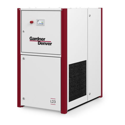
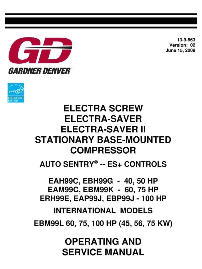
  9. Gardner Denver ELECTRA-SCREW ESG User manual

Gardner Denver ELECTRA-SCREW ESG User manual

13-9-601
1st EDITION
ELECTRA-SCREW@
STATIONARY
COMPRESSORS
@30 HP-
IMoDEL
040 HP-
MODEL
●50 HP-
MODEL
ESG
ESH
ESJ
13-9-601
WARRANTY
Subject to the terms and conditions hereinafter set forth, Gardner-Denver Company (the
Company) warrants products and parts sold by it, insofar as they are of its own manufacture,
against defects of material andworkmanship, under useandservice accordance with Company's
written instructions, recommendations and ratings for installation, operating, maintenance and
service of products, for aperiod of three months from the date of initial use, provided that such
three month period shall in no case extend beyond one year from the date of shipment by
Company. THIS WARRANTY IS LIMITED TO THE REPAIR OR REPLACEMENT, AS
COMPANY MAY ELECT, OF ANY DEFECTIVE PARTS, REGARDING WHICH, UPON
DISCOVERY OF THE DEFECTS, THE PURCHASER HAS GIVEN IMMEDIATE WRITTEN
NOTICE. Installation and transportation costs are not included. Company shall have the option
of requiring the return to it of the defective material, transportation prepaid, for inspection.
Because of varying conditions of installation and operation, all guarantees of performance are
subject to variation of 3% COMPANY DOES NOT WARRANT THE MERCHANTABILITY
OF ITS PRODUCTS AND DOES NOT MAKE ANY WARRANTY, EXPRESS OR IMPLIED,
OTHER THAN THE WARRANTY CONTAINED HEREIN. Company has not authorized
anybody to make any representation or warranty other than the warranty contained herein.
FOREWORD
Gardner-Denver ELECTRA-SCREW@ compressors are the result of advanced engineering and skilled
manufacturing. To be assured of receiving maximum service from this machine, the owner must exercise
care in its operation and maintenance. This book is written to give the operator and the maintenance
department essential information for day-to-day operation, maintenance and adjustment. Careful adherence
to these instructions will result in economical operation and minimum downtime.
TABLE OF CONTENTS
GENERAL INFORMATION .......................................................
CONTROLS AND INSTRUMENTS. .................................................
LUBRICATION –OILCOOLER, OIL FILTER AND SEPARATOR ..........................
AIR FILTERS .................................................................
COUPLING ...................................................................
INSTALLATION ...............................................................
STARTING AND OPERATING PROCEDURES ..........................................
MAINTENANCE SCHEDULE ......................................................
TROUBLE SHOOTING ...........................................................
COMPRESSOR OVERHAUL .......................................................
SECTION 1
SECTION 2
SECTION 3
SECTION 4
SECI’ION 5
SECTION 6
SECTION 7
SECTION 8
SECTION 9
SECTION 10
13-9-601 Page i
INDEX
NOTE: Numbers preceding dash are Section Numbers –numbers following dash are Page Numbers.
Addition of Oil Between Changes ................
Aftercooler ..............................
Aftercooler (Heat Exchanger Water Piping) . . , . . . . . . .
Air Filter .......................4–1.7–1.
Air Filter, Heavy-Duty .......................
AIR FILTERS (SECTION 4).... ..............
Air flow ...............................
Air& Oil Discharge Temperature ................
Air-Oil Systems Flow Diagram.. ................
Air Pressure Adjustment (Automatic Start-Stop) .......
Air Pressure Adjustment (Dual) ...,...,.........
Air Pressure Adjustment (Duomatic) . . . . , . , . . . . . . .
Air Pressure Gauge .........................
Air Receiver, Auxiliary, .....................
Air Receiver-Oil Reservoir .....................
Air Receiver Pressure Adjustment (Constant Speed) . . . . .
Alignment of Compressor &Motor.., ............
Alignment, Coupling . . . . . . . . . . . . . . . . . . ..5–1.
Assembly ...............................
Automatic Blowdown System. .................
Automatic Blowdown Valve.. .................
Automatic Start-Stop Control System. ......,......
Automatic Start-Stop (Duomatic) ................
Auxiliary Air Receiver .......................
Blowdown System, Automatic .......,..,.......
Blowdown Valve, Automatic. ..................
Blowdown Valve Piping ......................
3–2
6–1
6–2
8–1
4–1
4–1
1–1
3–6
3–1
2–6
2–6
2–9
2–2
6–1
3–4
2–3
O–8
7–1
o–2
3–5
2–2
2–6
2–8
6–1
3–5
2–2
6–2
Canopy Enclosure ..........................
Capacities, Oil, ...........................
Check, Compressor Oil System. ...,.,...........
Check, Daily .............................
Check List, Service .........................
Check Valve (Oil Reservoir) ...................
Circuit Breaker ...........................
6–1
3–2
3–6
7–1
8–1
2–2
2–1
Cleaning &Draining Oil System. ................3–2
Clearance Chart -Unit Cold.... ...............10–4
Cold Ambient Operation .....................3–2
Compression Principle .......................1–1
Compressor .............................1–1
Compressor Lubricants ......................3–2
Compressor Oil, ..........................7–1
Compressor Oil Cooler –Radiator Type. ........... 3–3
Compressor Oil Cooler –Water-Cooled Heat Exchanger . . 3–3
Compressor Oil Filter .......................3–3
Compressor Oil Inlet Temperature. ............... 3–6
Compressor Oil Separator..,.. ................ 3–4
Compressor Oil System ......................3–1
Compressor Oil System Check.... . . . . . . . . . . . . ..3–6
Compressor Outline ........................1–4
COMPRESSOR OVERHAUL (SECTION 10). . . . . . . . . 10–1
Condensate Ejector Drain .,... . . . . . . . . . . . . . . ..6–1
Constant Speed Control System ................. 2–2
Constant Speed (Duomatic Control). . . . . . . , . . . . . . . 2–8
Control Piping ...........................6–1
CONTROLS &INSTRUMENTS (SECTION 2). . . . . . . . 2–1
Control System (Automatic Start-Stop). . . . . . . . . . . . . 2–6
Control System (Constant Speed) ....,....,...... 2–2
Control System (Dual) .......................2–6
Control System (Duomatic) .................... 2–8
Control Valve, Oil Flow (Duomatic Unit Only). .,,.... 3–5
Control Valve, Water Flow (Heat Exchanger) ......... 3–4
Control Voltage ...........................2–1
coupling ...............................5–1
COUPLING (SECTION 5) ..,,... . . . . . . . . . . ..5–1
Coupling Alignment ....................5–1. 7–1
13-9-601
Daily Check .............................7–1
Differential Group, Pressure, ,.................. 3–5
Dimensions ..............................10–9
Disassembly Instructions . . . . ... . . . . . . . . . . . . . ..10–1
Discharge Pressure Valve, Minimum .......,....... 2–2
Discharge Service Line .......................6–2
Discharge Temperature, Air&Oil. ............... 3–6
Drain, Condensate Ejector.. ..................6–1
Draining &Cleaning Oil System . . . . . . . . . . . . . . . . . 3–2
Drain, Oil Reservoir ........................6–1
Dual Control System .......... ., ............2–6
Duomatic Control System .....................2–8
Dust Cup (Heavy-Duty Air Filter) ...,............ 4–1
Ejector Drti, Condensate ....................6–1
Electrical ...........................6–3.7–1
Electrical Wiring (Automatic Start-Stop) ........ 2–5, 2–6
Electrical Wiring (Constant Speed). ........,.. 2–3, 2–4
Electrical Wiring (Dual) ..................2–7. 2–8
Electrical Wiring (Duomatic) ...............2–9, 2–10
Element, Filter (Heavy-Duty) ....,.,.,.......... 4–1
Element Life, Filter (Heavy-Duty) ..,............. 4–2
Fan ..................................3–6
Filling Oil Reservoir ........................3–3
Filter, Air, .....................4–1.7–1.8–1
Filter, Compressor Oil .,..... . . . . . . . . . . . . . . ..3–3
Filter Element (Heavy-Duty) ...................4–1
Filter Element Life (Heavy-Duty) ................ 4–2
Filter, Heavy-Duty Air, ......................4–1
FILTERs, AIR (SECTION 4)...... . . . . . . . . . . ..4–1
Fits ..................................10–9
Flow Diagran -Air-Oil Systems ... ., . . . . . . . . . ..3–1
Foundation .............................6–1
Gauge, Air Pressure ........,. ,.............z–2
Gauge, Oil Level ..........................3–2
Gauge, Oil Temperature ......,...............2–2
Gauges &Instruments .......................2–2
Gear Data (Drive &Driven) ..,. . . . . . . . . . . . . . ..10–7
General (Controls &Instruments) ................ 2–1
GENERAL INFORMATION (SECTION 1) .......... 1–1
General (Installation) . . . . . . . . . . . . . . . . . . . . . ..6–1
Heat Exchanger Type Compressor Oil Cooler . . . . . . . . . 3–3
Heavy-Duty Air Filter .......................4–1
High Air Temperature Shutdown Switch .....,...... 2–I
High Oil Reservoir Pressure Shutdown Switch. ......,. 2–1
Honrmeter ..............................2–2
INFORMATION, GENERAL (SECTION 1). ......... 1–1
Inlet Line ..............................6–2
Inlet Pressure, Oil ............ .............3–6
Inlet Screen &Tube (Heavy-Duty Air Filter) . . . . . . . . . 4–2
Inlet Temperature, Compressor Oil ............... 3–6
Inlet Valve (Constant Speed).,.. ............... 2–3
Inlet Valve(Duomatic) ......................2–8
INSTALLATION (SECTION 6) ................ 6–1
INSTRUMENTS &CONTROLS (SECTION 2). ....... 2–1
Instruments &Gauges .......................2–2
Page ii
Light Test, Operating . . . . . . . . . . . . . . . . . . . . . ..7–1
Location (Installation )........ ...............6–1
Lubricants, Compressor ......................3–2
Lubrication, Cooling &Sealing. ................. 1–1
LUBRICATION –OIL COOLER, OIL FILTER
&SEPARATOR (SECTION ).............. 3–1
Maintenance of Air Filters ..........,..... 4-1, 4–2
MAINTENANCE SCHEDULE (SECTION 8) . . . . . . . . 8–1
Minimum Discharge Pressure Valve ............... 2–2
Minimum Operating Pressure (Automatic Start-Stop). .... 2–6
Minimum Operating Pressure (Constant Speed) . . . . . . . . 2–3
Minimum Operating Pressure (Dual) ..,........... 2–8
Minimum Operating Pressure (Duomatic) . . . . . . . . . . . . 2–9
Mixing Valve, Thermostatic (Radiator-Type Oil Cooler) . . . 3–3
Mode, Operating . . . . . . . . . . . . . . . . . . . . . . . . ..7–1
Motor Protection Devices ..................... 2–1
Oil& Air Discharge Temperature ................ 3–6
Oil-Air Systems Flow Diagram. .................3–1
Oil Capacities ............................3–2
Oil Change Interval .........................3–2
Oil, Compressor ...........................7–1
Oil Cooler, Compressor –Radiator Type ........... 3–3
Oil Cooler, Compressor –Water-Cooled Heat Exchanger . . 3–3
Oil Cooler Oil Pressure Drop... ................3–6
Oil Filter -Compressor ......................3–3
Oil Flow Control Valve (Duomatic Only) ........... 3–’5
Oil Inlet Pressure ..........................3–6
Oil Inlet Temperature, Compressor ............... 3–6
Oil Level Gauge ...........................3–2
Oil Pressure Drop, Oil Cooler... ...............3–6
Oil Quality ..............................3–2
Oil Reservoir -Air Receiver ...................3–4
Oil Reservoir Check Valve... .................2–2
Oil Reservoir Drain .........................6–1
Oil Reservoir -Filling ......................3–3
oil Reservoir Pressure Shutdown, High ............. 2–1
Oil Return ..............................3–5
Oil Separator, Compressor ....................3–4
Oil Specifications .........................3–1
Oil System ..............................3–1
Oil System Check, Compressor. ................. 3–6
Oil System-Draining&Cleaning ...............3–2
Oil Temperature Gauge . . . . . . . . . . . . . . . . . . . . ..2–2
On-Off Switches ..........................2–1
Operating Air Pressure Adjustment (Automatic Start-Stop) .2–6
Operating Air Pressure Adjustment (Dual) ........... 2–6
Operating Air Pressure Adjustment (Duomatic) . . . . . . . . 2–9
Operating Light Test ........................7–1
Operating Mode ...........................7–1
Operating Pressure, Minimum (Auto Start-Stop). .,..... 2–6
Operating Pressure, Minimum (Constant Speed) . . . . . . . . 2–3
Operating Pressure, Minimum (Dual) .............. 2–8
Operating Pressure, Minimum (Duomatic) . . . . . . . . . . . 2–9
OPERATING PROCEDURES &STARTING (SECTION 7) 7–1
Outline, Compressor . . . . . . . . . . . . . . . . . . . . . . ..1–4
OVERHAUL –COMPRESSOR (SECTION 10) ., . . . . . 10-1
Pilot, Subtractive ..........................2–2
Piping.................. ...............7–1
Piping, Blowdown Valve ......................6–2
Piping, Control ...........................6–1
Piping, Water (Water-Cooled Units) ............... 6–2
Pressure Adjustment, Air Receiver Section (Constant Speed) 2–3
Pressure Adjustment, Operating Air (Automatic Start-Stop) 2–6
Pressure Adjustment, Operating Air (Dual). . . . . . . . . . . 2–6
Pressure Adjustment, Operating Air (Duomatic). . . . . . . . 2–9
Pressure Differential Group... ................. 3–5
Pressure Drop, Oil Cooler Oil ..................3–6
Pressure Gauge, Air . . . . . . . . . . . . . . . . . . . . . . . ..2–2
Pressure, Minimum Operating (Automatic Start-Stop) . . . . 2–6
Pressure, Minimum Operating (Constant Speed) ........ 2–3
Pressure, Minimum Operating (Dual) ....,......... 2–8
Pressure, Minimum Operating (Duomatic) . . . . . . . . . . . 2–9
Pressure, Oil Inlet .........................3–6
Pressure Shutdown, High Oil Reservoir . . . . . . . . . . . . . 2–1
Pressure, System ..........................7–1
Pressure Valve, Minimum Discharge ............... 2–2
Radiator Type Oil Cooler .....................3–3
Rebuilding Data . . . . . . . . . . . . . . . . . . . . . . . . ..10–9
Receiver, Auxiliary Air.... ..................6–1
Reservoir Drain, Oil ........................6–1
Reservoir (Oil) Check Valve... ................2–2
Rotation ...............................7–1
Running Clearances .........................10–9
Safety Devices ............................2–1
Safety Valve .............................2–2
Screw Torque Tightening Recommendations. .........10–3
Sectional View of Compressor . . . . . . . . . . . . . . . . . . 10–3
Separator, Compressor Oil...... . . . . . . . . . . . . . . . 3–4
Service Check list .........................8–1
Service Liue, Discharge.......................6–2
Shutdown Switch, High Air Temperature ........... 2–1
Shutdown Switch, High Oil Reservoir Pressure ........ 2–1
Shutoff Valve, Water (Water-Cooled Heat Exchanger) .... 3–4
Specifications, Oil ..........................3–1
STARTING &OPERATING PROCEDURES (SECTION 7) 7–1
Starting unit -cold ........................7–1
Starting Unit -Hot ........................7–1
Stopping Unit ............................7–1
Subtractive Pilot ..........................2–2
Switch, High Air Temperature Shutdown ........... 2–1
Switch, High Oil Reservoir Pressure Shutdown . . . . . . . . 2–1
Switches, ’’On-Off’’ ........................2–1
System Pressure ...........................7–1
Temperature, Air& Oil Discharge . . . . . . . . . . . . . . . . 3–6
Temperature, Compressor Oil Inlet ............... 3–6
Temperature Gauge, Oil ......................2–2
Temperature Shutdown Switch, High Air . . . . . . . . . . . 2–1
Thermostatic Mixing Valve (Radiator Type oil Cooler) ... 3–3
Timed Automatic Start-Stop (Duomatic) . . . . . . . . . . . . 2–8
Torque Tightening Recommendations ..............10–3
TROUBLE SHOOTING (SECTION 9). ............ 9–1
Valve, Automatic Blowdown. ..................2–2
VaIve, Check (Oil Reservoir) ...................2–2
Valve, Inlet (Constant Speed) .................. 2–3
Valve, Inlet (Duomatic Control) .......,......... 2–8
Valve, Minimum Discharge Pressure ............... 2–2
Valve, Oil Flow Control (Duomatic Only) . . . . . . . . . . . 3–5
Va.lve Piping, Blowdown ......................6–2
Valve, Safety ............................2–2
Valve, Thermostatic Mixing (Radiator-Type Oil Cooler) . . . 3–3
Valve, Water Flow Control (Heat Exchanger) . . . . . . . . . 3–4
Valve, Water Shutoff (Water-Cooled Heat Exchanger) . . . . 3–4
Voltage, Control ..........................2–1
Water Flow .............................6–4
Water Flow Control Valve (Heat Exchanger) ......... 3–4
Water Piping (Water-Cooled Units). ......,........ 6–2
Water Shutoff Valve (Water-Cooled Heat Exchanger). . . . . 3–4
Wiring Diagram (Automatic Start-Stop) ............. 2–5
Wiring Diagram (Constant Speed) . . . . . . . . . . . . . , . . 2–4
Wiring Diagram (Dual Control) .................. 2–7
Wiring Diagram (Duomatic Control). . . . . . . . . . . . . . . 2–10
Wiring, Electrical ......................6–3.7–1
13-9-601 Page iii
SECTION 1
GENERAL INFORMATION
COMPRESSOR –The Gardner-Denver Model “ES”. Electra-Screw@ compressor is asingle stage, positive displacement
rotary machine using meshing helical rotors to effect compression. The input drive shaft and helical drive gear are supported
in the gear case by high capacity ball bearings; the drive gear meshes with adriven gear mounted on the main rotor shaft
to drive the rotors. Both rotors are supported between large capacity antifriction bearings located outside the compression
chamber. Single-width cylindrical roller bearings are used at the inlet end of the rotors. Two heavy-duty single row angular
contact ball bearings at the discharge end locate each rotor axially and carry all thrust loads.
COMPRESSION PRINCIPLE (Figure l-l) –Compression is accomplished by the main and secondary rotors synchronously
meshing in aone-piece cvlinder. The main rotor has four helical lobes 90° apart. The secondary rotor has six matching
helical grooves 60 apart to allow meshing
%— aoToa
.
with main rotor lobes.
FIGURE 1-1. –COMPRESSION CYCLE
The air inlet port is located on top of the compressor near the drive shaft end. The discharge port is near the bottom at
the opposite end of the compressor cylinder. Figure 1-1 is an inverted view to show inlet and discharge ports. The com-
pression cycle begins as rotors unmesh at the inlet port and air is drawn into the cavity between the main rotor lobes and
secondary rotor grooves (A). When the rotors pass the inlet port cutoff, air is trapped in the interlobe cavity and flows
axially with the meshing rotors (B). As meshing continues, more of the main rotor lobe enters the secondary rotor groove,
normal volume is reduced and pressure increases. Oil is injected into the cylinder to remove the heat of compression and
seal internal clearances. Volume reduction and pressure increase continues until the air/oil mixture trapped in the interlobe
cavity by the rotors passes the discharge port and is released to the oil reservoir (C).
AIR FLOW (Figure 1-3) –Air enters the air filter and passes through the inlet unloader valve to the compressor. After
compression, the air/oil mixture passes into the oil reservoir where more than 9970 of the entrained oil is removed by velocity
change and impingement and drops back into the reservoir. Amultiple element final separator removes the balance of the
oil and returns it to the system through tubing connecting the separator and compressor. The air then passes through the
reservoir check valve, the air receiver section and the minimum pressure valve to the plant air lines.
LUBRICATION, COOLING AND SEALING –Oil is forced by air pressure from the oil reservoir through the oil filter,
oil cooler and thermostatic mixing valve (mixing valve is not used with the water-cooled oil cooler), and discharges into
the compressor main oil gallery. Aportion of the oil is directed through internal passages to the bearings, gears and shaft
oil seals. The balance of the oil is injected directly into the compression chamber to remove heat of compression, seal
internal clearances and lubricate the rotors.
13-9-601 Section 1Page 1
13-9-601 Section 1Page 2
13-9-601 Section 1Page 3
.-
x
IL”
I
--i I
0
m1’
13-9-601 Section 1Page 4
SECTION 2
CONTROLS &INSTRUMENTS
GENERAL –The Gardner-Denver Model “ES”
systems:
Constant Speed
Automatic Start-Stop
Electra-Screw@ compressor units are available with four different control
Dual (Selective –Constant Speed or Automatic Start-Stop)
Duomatic (Selective –Constant Speed With Low Unloaded Horsepower or Automatic Start-Stop)
Unless customer specifications instruct otherwise, the Electra-Screw@ unit is prewired at the factory with all starter to
motor and control connections for the voltage specified on the order. It is necessary only to connect the unit starter to
the correct power supply and the shop air line and water line if the unit is the heat exchanger type. The standard unit is
supplied with the control system specified, an open drip-proof motor, NEMA 1starter enclosure and adust resistant control
enclosure/instrument panel.
CONTROL VOLTAGE –The control voltage for push buttons, lights, hourmeter, pressure switches, high discharge tem-
perature shutdown switch, blowdown valve, and other electrical control devices is II 5volts regardless of power supply
voltage. Atransformer in the control enclosure is connected to change the power supply voltage to 115 volt control
voltage.
CIRCUIT BREAKERS –The instrument panel for any of the four control systems incorporates two separate push-to-reset
type circuit breakers for high discharge temperature and high reservoir pressure shutdown switches (Figures 4-2, 7-2, 8-2
and 11-2). If either atemperature or pressure failure occurs, the circuit breaker button will pop up indicating which safety
device has stopped the unit.
DO NOT CONTINUE TO RESET THE CIRCUIT BREAKER IF THE SAME MALFUNCTION OCCURS WITHIN A
SHORT PERIOD. FIND AND CORRECT THE TROUBLE BEFORE RESUMING OPERA TION.
ON-OFF SWITCHES –The “On-Off” switch for the constant speed, automatic start-stop and dual control units has an
amber lighted “On” section. The timed duomatic control switch has agreen lighted “Load” section in addition to the “On”
section; the black bar on the bottom of this switch is nonfunctional. To replace the bulb (Sylvania 120 PSB or equal)
in the switch:
1. Turn power off at main breaker panel.
2. Open control panel.
3. Turn slotted locking screw on upper side of switch body counterclockwise 1/4 turn and remove switch body from
switch operator.
4. Remove old bulb located in stem of switch body and insert new bulb.
5. Reassemble switch body to operator and lock in” place by turning locking screw 1/4 turn clockwise.
SAFETY DEVICES –All four control systems incorporate these safety devices:
Motor Protection Devices –Overload heaters are furnished for the starter in the voltage range specified. There are three
(3) overloads in the starter of proper size for the starter and its enclosure. When replacing or changing overloads, be sure
to select from a 3 overload heater table since the use of athird overload derates each overload for agiven enclosure due to
the extra heat. An overload from a2overload heater table would be undersize.
The overload heaters are in acommon overload block in the starter and have asingle common percentage adjustment
with a 90 to 110% range. The unit is set at the factory on the 100% mark.
High Air Temperature Shutdown –The compressor is protected from lubrication failure by ahigh discharge temperature
switch located in the discharge pipe between the compressor discharge and the oil reservoir. This switch is wired into the
motor control circuit and will shut the unit down if discharge temperature exceeds 225° F. The manual reset is located
as described in “Circuit Breakers” paragraph, and must be reset any time unit is shut down due to high air discharge
temperature.
High Oil Reservoir Pressure Shutdown –The unit is protected from high oil reservoir pressure by apressure switch located
under the control panel and wired into the motor control circuit with piping to the oil reservoir section. This switch will shut
the unit down if pressure in the oil reservoir exceeds 165 PSIG, acting as asafety valve without loss of oil. THE MAXIMUM
ALLOWABLE SETTING IS 165 PSIG. The manual reset is located as described in “Circuit Breakers” paragraph, and must
be reset any time unit is shut down due to high oil reservoir pressure.
13-9-601 Section 2Page 1
Automatic Blowdown Valve (Figure 1-3) –Asolenoid valve piped into the oil reservoir section between the oil separator
and reservoir check valve and wired into the motor control circuit will release pressure from the oil reservoir each time
the motor stops on constant speed, automatic start-stop or dual control systems. On the duomatic system, pressure will
be released from the oil reservoir each time the compressor unloads or is shut down. A3/16” diameter orifice is used to
maintain blowdown time to about 45 seconds and prevent oil carry-over due to too rapid arelease of press tire. Asilencer
terminates the blowdown line to muffle air discharge noise.
Safety Valve (Figures 2-1 &4-1) installed in the air receiver section is set at the factory to 110% of the specified operating
pressure for protection against overpressure of the air receiver section. Periodic checks should be made to insure its proper
operation. Never operate the unit without aproper safety valve setting.
NEVER DISCONNECT SAFETY DEVICES THAT PROTECT THE UNIT.
INSTRUMENTS AND GAUGES (Figures 4-2, 7-2, 8-2 &11-2) –The constant speed and the automatic start-stop units
have alighted “ON-OFF” push button.
The dual control unit has alighted selector switch with “CON-OFF” and “AUTO-OFF” push buttons for thetwo modes
of operation.
The duomatic control unit has alighted “ON-OFF” push button with lighted sections which indicate “On” (compressor
running) and “Load” (compressor loaded).
All four control system instrument panels incorporate the following:
Hourmeter –Acontinuous reading (nonreset) type hourmeter displays the accumulated operating time of the unit and
provides aconvenient means for scheduling changes and servicing of oil supply, Falters, separator and other devices.
Air’ Pressure Gauge –Adirect reading air pressure gauge indicates air pressure in the air receiver section of the reservoir.
Oil Temperature Gauge –Adirect reading temperature gauge indicates compressor oil inlet temperature.
MINIMUM DISCHARGE PRESSURE VALVE (Figure I-2) –An internal
pilot operated minimum pressure valve is used in the discharge line from
the air receiver section of the reservoir to provide apositive pressure on
the oil system of the compressor and prevent excessive oil carry-over into
shop air lines even when the air service valve is fully open. The amount
of oil carry-over into the air service line depends on the operating pressure.
Anormal carry-over amount is one pint per 100 hours of operation at
100 PSIG.
The valve incorporates an orifice which, when air is flowing through it,
maintains approximately 65 PSIG in the air receiver section. Aspring-
loaded piston valve senses air pressure in the air receiver section. When
the system pressure rises above 65 PSIG, the piston spring is overridden
and the valve opens to full porting.
FIGURE 1-2. –MINIMUM DISCHARGE The valve does not require maintenance or adjustment. If the valve fails
PRESSURE VALVE to function, check piston O-rings for sealing, piston orifice for restriction,
or piston and valve seat for burrs and dirt.
CHECK VALVE (Oil Reservoir) (Figures 2-2 &1-3) –AVALVE
renewable resilient disc-type check valve between the oil reser-
voir (separator) and air receiver sections prevents backflow of Al R
air when the unit stops, unloads or is shut down. 1
FLOW
CONSTANT SPEED CONTROL SYSTEM (Figures 3-2, 4-2 &
5-2) –The Constant Speed Control system is used where BUMPER
requirements for air are high for long periods, causing the unit
to remain loaded most of the time. The “On-Off’ switch and FIGURE 2-2. –RESERVOIR CHECK VALVE
instrument panel is shown in Figure 4-2. The control is a
stepless pneumatic system which regulates the compressor inlet
to match the air demand made on the compressor. Effective from Oto 100% of compressor capacity, the system opens
the inlet valve as air is drawn from service valve, maintains aconstant valve opening as air demand levels off, or closes the
valve when the demand ceases. This system includes the subtractive pilot and inlet valve.
Subtractive Pilot –The subtractive pilot is aspring-loaded diaphragm-actuated valve that regulates air pressure from the air
receiver section to the unloader piston. The pilot admits air to the inlet valve piston when an air receiver section pressure
equal to the pilot low setting is reached. The air begins to pass through pilot to the piston, and the inlet valve begins to
close. As the air receiver section pressure increases the pilot pressure also increases on the inlet valve piston, closing the
inlet valve. At full receiver pressure (pilot unload setting) the pilot is exerting full differential pressure on the inlet valve
13-9-601 Section 2Page 2
piston and the inlet valve is fully closed. AS the air receiver section pressure falls, the pilot exerts proportionally less pressure
on the inlet piston allowing the inlet piston spring to return the piston and the inlet valve to open. Normal pilot setting
(unload) is 105 PSIG, but the pilot can be adjusted from 50 to 150 PSIG. The differential range of approximately 15 PSI
cannot be changed.
Example with normal setting of 90-105 PSIG:
Air Receiver Pressure In Inlet
Pressure Control System Valve Compressor
85 0
90 0
95 5
100 10
105 15
Irdet Valve (Figure 3-2) –The inlet valve is a
piston-actuated device which controls the com-
pressor inlet and operates on air pressure from
the subtractive pilot, The valve is closed when
full pressure is on the system and changes degree
of opening in direct response to system pressure
changes.
The inlet valve contains piston spring “F” which
returns the unloaded piston and allows the inlet
valve to open as pressure decreases, and valve
spring “G” which retums the inlet ValVe to closed
position on shutdown of the compressor and pre-
vents oil backflow from the compressor to the
air filter.
Air Receiver Section Pressure Adjustment –Start
the unit. Close the air service line valve, allow
the air receiver section to build to full pressure
and the unit to unload, and proceed as follows:
AIR RECEIVER PRESSURE TOO HIGH:
1. Loosen the subtractive pilot locknut. Back
the adjusting screw out about one turn.
2. Open the air service line valve and bleed
air from the receiver section so that the
compressor loads again. Close the valve and
aUow the compressor to unload.
AIR PRESSURE GAuGE *M~ER ,,OM,,~,GHT
\\
“OFF,, 8UT?QN
OIL TEMP GAuGE- HOURMETER7ON,, BUTTON77
HIGH DISCHARGE PRESSURE SWITCHJ 9
CONSTANT SPEED CONTROL
FIGURE 4-2. –
CONSTANT
iu
INSTRUMENT PANEL
SPEED CONTROL
Open At full capacity
closing Reduced capacity
Closing Reduced capacity
Closed Not compressing
\——.—/LOCKNUT
ADJUSTING SCREW C74830
FIGURE 3-2. –INLET VALVE
FOR CONSTANT SPEED CONTROL
3. Repeat steps 1and 2until proper pressure
Tighten the locknut. is obtained.
AIR RECEIVER PRESSURE TOO LOW:
1. Loosen the subtractive pilot locknut.
2. Turn the adjusting screw in until proper pressure is obtained.
3. Tighten the locknut.
DO NOT ADJUST THE OPERATING AIR PRESSURE HIGHER
THAN THE MAXIMUM STAMPED ON THE UNIT NAMEPLATE.
MINIMUM OPERATING PRESSURE IS 6S PSIG.
Electrical Wiring –Figure 5-2 is the wiring diagram for the unit
with Constant Speed Control.
13-9-601 Section 2 Page 3
SEE NOTE “A” SEE NOTE “B”
M
\1+
‘L sTI
POWER L2 TZ COMP
SUPPLY L3 MTR
Ts
‘EE‘OTE“’”-4
“o”
NOTE ‘*A” FUSED SWITCH OR CIRCUIT BREAKER (NOT FURNISHED As STANDARD ITEM –IF ORDERED IT MUST BE REMOTE MOUNTED BY
CUSTOMER).
NOTE B–SINCE MOST A.C. MDTDRS ARE WOUND FOR DUAL vOLTAGE BE CERTAIN LEADS ARE CDNNECTED FOR THE CORRECT VOLTAGE,
NOTE C–STANDARD TRANSFORMER VOLTAGES ARE 230/460/575 VDLTS pRIMARy, IIs/95 VOLTS SECONDARY, 50/60 Hz (PART NO, 24CA43).
ALTERNATE TRANSFORMER AVAILABLE FOR 208/277/380 VOLTS PRIMARY, 1I5/9S VOLTS SECONDARY, 50/60 Hz (PART NO, 24CA44).
NDTE D“ x3 TERMINAL ON TRANSFORMER 1s GROUNDED UNDER MOuNTING FOOT OF TRANSFORMER THIS GROUNDING JUMPER GREEN
WIRE) 1S EASILY REMDVED IF GROUNDING OF CDNTROL CIRCUIT 1S NOT DESIRED.
FUSE – 2 AMP – 250 VBUSS FUSETRON FRN2.
H.D.P.S. -HIGH DISCHARGE PRESSURE SWITCH 88A305 SET 140-160 LBS
H.D.T.S. –HIGH DISCHARGE TEMPERATURE SWITCH 21B90 SET 230° F,
H.M. –HDURMETER 2009369 – I15 V– 60 Hz 12009370- 115V- 50 Hz ALTERNATER
M. –MDTOR STARTER COIL AND CONTACTS. ‘---
M.W.V. –MAGNETIC WATER VALVE –90AC 118 – 115 VAC TWD-WAY NORMALLY CLDSED -3/4” (2W,N, C.)
0. L. -OVERLOAD,
RESET –TEMPERATURE AND pREssuRE –24cA41. REsET BUTTON SEAL –24cA42. THE 1/2 INCH EXTENSION OF THE RESET BUT-CDN RED
PLUNGER (1/4 INCH NORMAL) GIVES VISUAL 1NDICATION DF THE SHUTDDWN TRDUBLE POINT. THE RESET BUTTON WILL NDT
RESET IF TROUBLE STILL PERSISTS WHEN THE RESET BUTTDN 1S PRESSED.
SOL. –AUTOMATIC BLDWDOWN SOLENDID VALVE –90AC162 11S VAC –TWO-WAY NORMALLY OPEN –1/2” (2W.N,O, ).
o-TERMINAL DN RESET BUTTONS :0:- INDICATING LIGHTS -24cA40 (SYLVANIA 120 P.SB. ,
,W
‘“y:’-’’’z’*---- ALL EQUIPMENT MUST BE CONNECTED AND PHASEDEXACTLY AS SHOWN. ALL PIPING. WIRING, AND OTHER EQUIPMENT NOT SPECIFIED ON
ORDER 1S TD BE SUPPLIED BY DTHER THAN GARDNER.DENVER COMPANY.
C74834 ICONTROL BOX ~SEE NOTE “D”
+1’11~ 111!1 !Illllll I
4L,JI f’ f (I 7.,. A\\A A /
I149B
. .
\c.
BACK-VIEW OF DOOR
?
HOURMETER
~~
F
OVER PRESS, OVER TEMP.
PREsS TO RESET
(WHEN USED)
FIGURE 5-2. –WIRING DIAGRAM FOR UNIT WITH CONSTANT SPEED CONTROL
ul
ESEE NOTE “A” SEE NOTE “E”
MOLS 7
NOTE ..~ –FUSED SWITCH OR CIRCUIT BREAKER (NOT FURNISHED AS STANDARD ITEM –IF ORDERED IT MUST BE REMOTE MOUNTED BY
CUSTOMER).
~LI
POWER
\~- . .
NOTE 4CS’–
L2 NOTE U–
SUPPLY L3
‘EENOTE“’”*4
sINcE MOST A.C. MOTORS ARE WOUND FOR DUAL VOLTAGE BE CERTAIN LEADS ARE CONNECTED FOR THE CORRECT VOLTAGE.
STANDARD TRANSFORMER VOLTAGES ARE 230/460/57S VOLTS PRIMARY, II 5/95 VOLTS SECONDARY, 50/60 Hz (PART NO. 24CA43).
ALTERNATE TRANSFORMER AVAILABLE FOR 208/277/380 VOLTS PRIMARY, 115/95 VOLTS SECONDARY, 50/60 Hz (PART NO. 24CA44).
X3 TERMINAL ON TRANSFORMER 1S GROUNDED UNDER MOUNTING FOOT OF TRANSFORMER. THIS GROUNDING JUMPER (GREEN
WIRE) 1S EASILY REMOVED IF GROUNDING OF CONTROL CIRCUIT 1S NOT DESIRED.
MAXIMUM 20 STARTS PER HOUR.
,,, .,
6
x*
-%
SEE NOTE “O”
r9--- —------ ;~7--- ____,.__,
86!5 OL’S f.
FU
12 3 1;1 31! x, x3
1. ---- ---- .1------ —----J ~
H,D.T.S. H. D, P
I‘> AON I
t,,t..””’
~.”
SEE NOTE “E “
C74835
BLOW OOWN SOi
II
AP, S.
FUSE –
H.D.P.S. –
H.D.T.S. –
H,M, -
M,
M.WV. –
0. L.
RESET -
SOL
o-
AIR PRESSURE SWITCH 2009353 NDRMALLY SET 90-I00 LBS, IF RESET (150 LBS. MAXIMUM CUTOUT SETTING)
2AMP –25D V–BUSS FUSETRDN FRN2.
HIGH DISCHARGE PRESSURE SWITCH 88A305 –SET 140-160 LBS.
HIGH DISCHARGE TEMPERATURE SWITCH 21B90 –SET 230° F.
HO URMETER 2DD9369 – 115 V– 60 Hz (2 DD9370 – 115 V– 50 HZ ALTERNATE).
MDTDR STARTER CUIL AND CONTACTS,
MAGNETIC WATER VALVE –9DACI IS – 115 VAC –TWO-WAY NORMALLY CLOSEO –3/4” (2w.N.C.).
DVERLDAD,
TEMPERATURE AND PRESSURE –24CA41, RESET BUTTON SEAL – 24CA42. THE 1/2 INCH EXTENS1ON OF THE RESET BUTTON RED
PLUNGER (1/4 INCH NORMAL) GIVES VISUAL INDICATION OF THE SHUTDOWN TROUBLE POINT. THE RESET BUTTON WILL NOT
RESET IF TROUBLE STILL PERSISTS WHEN THE RESET BUTTON 1S PRESSED.
AUTOMATIC BLOWDOWN SOLENOID VALVE –9DAC162 – 115 VAC –TWO-WAY NORMALLY DPEN -1/2” (2W.N.O.).
TERMINALS ON RESET BUTTONS ;a -INDICATING LIGHTS –24CA40 (SYLVANIA 120 P.S.B.)
ALL EoUIPMENT MUST BE CDNNECTED ANO PHASED EXACTLY AS SHOWN. ALL PIPING, WIRING, AND OTHER EQUIPMENT NOT SPEC3F1ED ON
OROER- 1S TD BE SUPPLIED BY OTHER THAN GARDNER-DENVER COMPANY
1
cONTROLBOxr-’%l~:z
L,J I~
11498
1
(/
R.,
10
24 CA47
l———
BACK-VIEW OF OOOR
9
HOURMETER
jj
C
OVER PRESS OVER TEMP
PRESS TD RESET
I(wHEN uSEO)
FIGURE 6-2. –WIRING DIAGRAM FOR UNIT WITH AUTOMATIC START-STOP CONTROL SYSTEM
AUTOMATIC START-STOP CONTROL SYSTEM (Figures 6-2 &7-2
where requirements for air are for short and/or intermittent periods.
air receiver section pressure falls to apredetermined point and
stops the motor when the air receiver section pressure rises to a
predetermined point. An auxiliary air receiver ,with adequate
volume must be used with this system to prevent rapid cycling
of the unit. Occasionally, shop lines are of such length as to
provide adequate volume, but this should be checked carefully
before using the unit without an auxiliary air receiver.
The operating pressure of the system is controlled by the air
pressure switch located under the control panel, Figure 7-2.
The switch is piped to the air receiver section of the reservoir
and connected to the electrical circuit in the control box.
Operating Air Pressure Adjustment –Start the unit. Close the
air service line valve sufficiently to hold an air receiver section
pressure near the system pressure desired. Remove pressure
switch cover.
)–The Automatic Start-Stop Control system is used
The system automatically starts the motor when the
AIR PREssURE GAUGE
\
AMBER ,,oN,, LIGHT OFF,, BUTTON
OIL TEMP GAuGE ~17
HOURMETER7 “ON,,RuTTON,
HIGH DISCHARGE PRESSURE SWITCH
AUTO START- STOP CONTROL 79
SET
1.
2.
3.
SET
1.
2.
3.
4.
FIGURE 7-2. –INSTRUMENT PANEL –
FULL RECEIVER PRESSURE (MOTOR STOP) POINT –AUTO START-STOP CONTROL
Turn the upper adjusting screw on the pressure switch
until the pointer on left edge indicates the desired pressure; turn clockwise to raise pressure, counterclockwise to lower.
Close the air service valve, allow air receiver pressure to build until the unit stops and observe pressure.
Open the air service line valve, bleed air from the air receiver section until the unit starts, then repeat steps 1and 2
until the proper pressure is obtained.
LOW RECEIVER PRESSURE (MOTOR START) POINT –
With power on, air receiver section at full pressure and air service line valve closed, set lower (differential) adjusting
screw near desired pressure; turn counterclockwise to increase differential, clockwise to decrease. Full receiver pressure
minus differential is the low receiver pressure (motor start) point. Differential range is approximately 2-18 PSIG on
the circular scale above the adjusting screw.
Open the air service line valve, bleed air from the air receiver section so that the motor starts and observe pressure
at that point.
Repeat steps 1and 2until the desired low receiver pressure point is obtained.
Replace the pressure switch cover.
DO NOT ADJUST THE OPERATING AIR PRESSURE HIGHER THAN THE MAXIMUM STAMPED ON THE UNIT
NAME PLATE. MINIMUM OPERA TING PRESSURE IS 65 PSIG.
Electrical Wiring –Figure 6-2 is the wiring diagram for the unit with Automatic Start-Stop Control system.
DUAL CONTROL SYSTEM (Figures 8-2 &9-2 –The Dual Control system incor orates both the Constant Speed Control
f
and the Automatic Start-Stop Control systems for use where air requirements vary rom high usage for long periods to short
and intermittent periods of use. When the air use is high, operate
HOUmtTER
Ai,RPRESSURE GAuGE Y
1.
the unit at constant speed to eliminate excessive starting and
;::;:::;:;::”2E:;7 stopping of the unit. When the air demand is low, operate the
hunit on automatic start-stop to eliminate long unloaded periods
and wasted power. The unit control panel (Figure 8-2) incor-
[orates both CON and AUTO sections in the On-Off push
utton. These buttons are interlocked so that the unit cannot
be changed from one mode of operation to the other unless
:://= &l= the unit is first stopped.
hauxiliary air receiver of adequate volume must be used with
this system to prevent rapid cycling on automatic start-stop.
IOccasionally, shop lines are of such length as to provide adequate
volume, but this should be carefully checked before using the
AIR PRESSURE SWITCH -unit without an auxiliary air receiver.
DUAL CONTROL HIGH O!SCWARGE PRESSURE SWITCH
Operating Air Pressure Adjustment –With unit operating on CON
FIGURE 8-2. –INSTRUMENT PANEL –section of the On-off push button, follow procedure for Constant
DUAL CONTROL Speed system pressure adjustment on page 3of this section.
13-9-601 Section 2Page 6
N
‘E’‘0’’”’”-4
~
~3---------
S-1~7-----; ----?5 “L’S
-%
“[SEE ‘:” ‘D”
31!1 3II xl x3
L---- -.--. J----- ---. -J ~
H.D.TSH,O.RS.
L%! l-o 2’ L‘
‘ON”‘n’
\SEE NOTE “E”
C74836
STARTER
LI L2 L3
5-#14R:l, Z,3,4,5
11498
NOTE A–FusED swITcH OR CIRCUIT BREAKER (NOT FuRNIsHED AS STANDARD ITEM –IF ORDERED IT MUST BE REMOTE MOUNTED By
CUSTOMER),
NOTE B, –SINCE MOST A.C. MDTORS ARE WDUND FDR DUAL VOLTAGE BE CERTAIN LEADS ARE CONNECTED FOR THE CORRECT VOLTAGE
NOTE C’ –STANOARO TRANSFDILWER VOLTAGES ARE 230/460/57S VOLTS PRIMARY. 115/95 VDLTS SECONOARY, S0/60 Hz (PART No. 24CA43).
ALTERNATE TRANSFORMER AVAILABLE FOR 208/277/380 VOLTS PRIMARY, 115/9S VOLTS SECONDARY, 50/60 Hz (PART NO, 24CA44).
NOTE <D” –X3 TERMINAL ON TRANSFORMER IS GROUNDED UNDER MOUNTING FOOT OF TRANSFORMER. THIS GRDUNDING JUMPER (GREEN
WIRE) IS EASILY REMOVED IF GROUNDING OF CONTRDL CIRCUIT 1S NOT DESIREO.
NOTE 4E –MAXIMUM 20 STARTS PER HOUR
A,P,S,
FUSE
H,D.P.S.
H.O.T.S.
H,M.
M,
MW,V,
0, L.
RESET
30L.
–AIR PRESSURE SWITCH 2DD9353 NDRMALLY SET 90-100 LBS. IF RESET (150 LBS. MAXIMUM CUTOUT SETTING)
-2AMP – 250 V–BUSS FUSETRON FRN2.
-HIGH DISCHARGE PRESSURE SW3TCH 88A305 –SET 140-160 LBS,
–HIGH DISCHARGE TEMPERATURE SWITCH 21B90 –SET 230° F,
–HOURMETER 2DD9369 – 115 V– 60 Hz (2009370 – 115 V– 50 Hz ALTERNATE).
-MOTOR STARTER COIL AND CONTACTS,
–MAGNETIC WATER VALVE –90ACI 18 -115 VAC -TWD-WAY NOW ALLY CLOSEO –3/4 (2W.N. C,).
–OVERLOAD.
-TEMPERATURE ANO PRESSURE –24CA41. RESET BUTTON SEAL –24CA42, THE 1/2 INCH EXTENS1ON OF THE RESET BUTTON RED
PLUNGER (1/4 INCH NORMAL) GIVES VISUAL INDICATION OF THE SHUTDDWN TROUBLE POINT, THE RESET BUTTON WILL NOT
RESET IF TROUBLE STILL PERSISTS WHEN THE RESET BUTTON IS PRESSED,
–AUTOMATIC BLOWDOWN SOLENDID VALVE –90AC162 -IIS VAC –TWO-WAY NORMALLY DPEN –1/2” (2W,N, D,).
O-TERMINAL8 ON RESET BUTTONS ;0: -INDICATING LIGHTS -24CA4CI (SYLVANIA ,20 P.S,B,,
ALL EQUIPMENT MUST BE CONNECTEO AND PHASEOEXACTLY AS SHOWN.ALL PIPING, WIRING, ANO OTHER EQUIPMENT NOT SPECIFIED DN
ORDER 1S TO BE SUPPL3E0 BY OTHER THAN GARDNER. DENVER COMPANY,
,ONTROL: , , ;-
g:
3106+
A,PS H.D,PS
AA(
q
10 ,A 4
9 3
9 10
24CA48
9 10
BACK VIEW OF DOOR
?
HOURMETER
~~
~mfl
7I9
68
57
OVER PRESS OVER TEMP
PREss TO RESET
I(WHEN USEO)
FIGURE 9-2. –WIRING DIAGRAM FOR UNIT WITH DUAL CONTROL SYSTEM
With unit operating on the AUTO section of the On-Off push button, follow the procedure for Automatic Start-Stop
system pressure adjustment on page 6of this section.
The pressure switch unload point must be set approximately 3PSI lower than the subtractive pilot unload point to prevent
ovem”ding and closing of the inlet valve by the pilot on Au tomatic Start-Stop operation
DO NOT ADJUST THE OPERATING AIR PRESSURES HIGHER THAN THE MAXIMUM STAMPED ON THE UNIT
NAME PLATE. MINIMUM OPERA TING PRESSURE IS 65 PSIG.
Electrical Wiring –Figure 9-2 is the wiring diagram for the unit with Dual Control system,
DUOMATIC CONTROL SYSTEM (Figures 10-2, 11-2 &12-2) –The Duomatic Control system is used where air require-
ments vary widely, change in frequency of demand and where it is desirable to have some degree of control over the length
of time the motor will run after the compressor unloads. During the time the compressor is unloaded with the motor running,
the unit draws only about 20% of loaded power at 100 PSIG.
The Duomatic Control system offers three modes of operation controlled by the adjustable timer on the instrument panel
(Figure 11-2).
Constant Speed –When the timer is set in the space between 30 and O, the unit will run continuously. The inlet valve will
oen and allow the compressor to load when the pressure switch low setting is reached. When the pressure switch high setting
(full receiver pressure) is reached, the inlet valve closes, unloading the compressor. Each time full pressure is reached, the
oil reservoir section blows down through the automatic blowdown valve to reduce the unloaded horsepower. The LOAD
indicator light will signal whether unit is loaded (On) or unloaded (Off). The ON indicator light will remain on as long as
the On-Off switch ON push button is depressed.
Automatic Start-Stop –When the timer is set at O, the unit will start and inlet valve will open each time the pressure in the re-
ceiver section falls to the pressure switch low setting. When the pressure rises to the pressure switch high setting, the unit will
stop, the inlet valve will close, and the oil reservoir section will blow down. The LOAD indicator light will remain on only when
the compressor is running. The ON indicator light will remain on as long as the On-Off switch ON push button is depressed.
Timed Automatic Start-Stop –When the timer is set between Oand 30, the unit will start and the inlet valve open when
the pressure in the receiver section falls to the pressure switch low setting. When the pressure rises to the pressure switch
high setting, the unit wiU unload (LOAD light off), the inlet valve will close, the motor will continue to run and the oil
reservoir section blow down. If system pressure does not fall to the pressure switch low setting within the time set on the
timer, the unit will stop. The ON indicator light will remain on as long as the On-Off switch ON push button is depressed.
When air is again required, the unit will start, the timer will reset and the loaded-unloaded-stop cycle will repeat.
The timer should be set beyond the one (1) minute mark since the repeat accuracy of the timer between the zero (0) and
one (1) minute marks is not reliable. Second, the blowdown valve requires about 45 seconds to completely blow down the
oil reservoir. If the compressor restarts before the reservoir is blown down, oil mist is carried over into the air lines. Finally,
repeated compressor starting under loaded conditions can cause motor failure.
AIR
FLOW
C74435
FIGURE 10-2. –INLET VALVE
FOR DUOMATIC CONTROL
13-9-601 Section 2
An auxiliary air receiver with adequate volume must
be used with the Duomatic Control system to prevent
ra id cycling of the unit. Occasionally, shop lines are
f
osuch alength as to provide adequate volume, but
this should be carefully checked before using the unit
without an auxiliary air receiver.
The air pressure switch located under the unit control
panel (Figure 11-2) controls operating pressure of the
system by opening and closing inlet valve (Figure 7-2)
asin Constant Speed and Timed Duomatic operation,
or by starting and stopping unit as in Automatic Start-
Stop operation. The switch is piped from the air receiver
section to the magnetic unloader valve and connected
to the electrical circuit in the control box.
Inlet Valve (Figure 10-2) –The piston-actuated inlet
valve controls the compressor inlet and operates on air
pressure from the control circuit. The valve is closed
when preset full pressure is on the system, and open
when the pressure in system falls to apreset minimum.
The inlet valve contains piston spring” F“ which returns
piston and allows the inlet valve to open when the
pressure is removed, and valve spring “G” which returns
the valve to closed position on shutdown of the com-
pressor to prevent blowback from the compressor to the
air filter. The control orifice prevents valve “slam”.
Page 8
Operating Air Pressure Adjustment –Set the timer for constant
valve sufficiently to hold an air receiver section pressure near
cover.
SET FULL RECEIVER PRESSURE (COMPRESSOR UNLOAD)
POINT –
1. Turn upper adjusting screw on the pressure switch until
pointer on the left edge indicates desired pressure.
2. Close the air service line valve and allow the air receiver
section pressure to build until the compressor unloads.
3. Note air receiver pressure shown on the instrument panel
gauge. If not the pressure desired, open air service line
valve and bleed air from the air receiver section until the
compressor 10ads again. Repeat steps 1and 2until the
proper unloaded pressure is obtained.
speed operation. Start the unit and close air service line
the desired system pressure. Remove the pressure switch
A,R PRESSURE GAuGE
\
OIL TEMP GAuGE --~ ,owB~:Y7 r“”’:::~
HIGH DISCHARGE PRESSURE SWITCH
TIMED DUOMATIC CONTROL
yg
SET LOW RECEIVER PRESSURE (COMPRESSOR LOAD)
POINT –FIGURE 11-2. –INSTRUMENT PANEL –
TIMED DUOMATIC CONTROL
1. With power on, air receiver section at full pressure and
air service line valve closed, set lower (differential) adjust-
ing screw near desired pressure. Full receiver pressure minus differential is the low receiver (compressor load) point.
Differential range is approximately 2-18 PSIG on the circular scale above the adjusting screw.
2. Open the air service line valve, bleed air from the air receiver section so that the compressor loads and note pressure
obtained.
3. Repeat steps 1and 2until desired low receiver pressure point is obtained.
4. Replace pressure switch cover.
DO NOT ADJUST THE OPERATING AIR PRESSURE HIGHER THAN THE
NAME PLATE. MINIMUM OPERA TING PRESSURE IS 65 PSIG.
Electrical Wiring –Figure 12-2 is the wiring diagram for the unit with Duomatic
MAXIMUM STAMPED ON THE UNIT
Control system.
13-9-601 Section 2Page 9
SEE NOTE “6”> NOTE A–FUSED SWITCH OR CIRCUIT BREAKER INOT FURNISHED AS STANDARD ITEM IF ORDERED IT MUST BE REMDTE MOUNTED BY
SEE NOTE “D’”=
CUSTOMER)
NOTE B–SINCE MOST AC MOTDRS ARE wOuND FOR DUAL VOLTAGE BE CERTAIN LEADS ARE CONNECTEDFOR THE CORRECT VOLTAGE.
NOTE c,, –STANDARD TRANSFORMER vDLTAGEs ARE 230/460/s75 VOLTS pRIMARY, 115/95 VDLTS SECONDARY, 50/60 Hz IPART NO 24cA43).
ALTERNATE TRANSFORMER AVAILABLE FOR 208/277/380 VOLTS PRIMARY, 1I5/95 VDLTS SECONDARY, S0/60 Hz (PART ND 24CA44).
NOTE D- X3 TERMINAL ON TRANSFORMER IS GROUNDED UNDER MOUNTING FOOT OF TRANSFORMER. THIS GROUNDING JUMPER (GREEN
WIRE) 1S EASILY REMOVED IF GROUNDING OF CONTROL CIRCUIT IS NOT DESIRED.
A.P.S.
FUSE
H,D.P.S.
H.D.T,S.
H,M
LC, LO,
LC,T,O.
M
Mu
M,WV,
O.L.
RESET
A
TI T2 T3
o
OMI?
MTR
5-#14R: 1, 2,3,4,5
#
FIGURE 12-2. –
o
–AIR PRESSURE SWITCH 2LH39353 NDRMALLy SET 90-100 LBS. IF RESET (1S0 LBS. MAXIMUM CUTOUT SETTING).
– 2 AMP – 250 V–BUSS FUSETRON FRNz
–HIGH DISCHARGE PRESSURE SWITCH 88A305 –SET 140160 LBS
–HIGH DISCHARGE TEMPERATURE SWITCH 21B90 –SET 230° F,
HOURMETER 2oiz9369 –I15 v 60 HZ (2009370- 115 v – 50 HZ ALTERNATE)
–INSTANTANEOUS CLOSING ON ENERG1ZATION –INSTANTANEOUS OPENING ON DE-ENERGIZATION,
–INSTANTANEOUS CLOSING ON EN ERGIzATION TIME OPENING ON DE. EN ERGIZATION.
MOTOR STARTER COIL AND CONTACTS,
–MAGNETIC UNLOADER –90AC183 – 115 V–THREE-wAY NDRMALLY OPEN (3 W,N.O, ),
–MAGNETIC WATER VALVE –90AC118 – 115 VAC –TWO-WAY NORMALLY CLOSED –3/4’, {2 W.N. C.)
OVERLOAD,
TEMPERATURE AND PREssURE –24cA41. RESET BUTTON sEAL –24cA42. THE 1/2 INCH EXTENSION OF THE RESET BUTTON RED
PLUNGER 1/4 INCH NORMAL IGIVES VISUAL INDICATION OF THE SHUTDOWN TROUBLE POINT, THE RESET BUTTON WILL NOT
RESET IF TRDUBLE STILL PERSISTS WHEN THE RESET 8UTTON IS PRESSED.
–AUTOMATIC 8LOWDOWN SOLENOID VALVE –90AC162 – 115 VAC –TWO-WAY NDRMALLY OPEN –1/2” (2W.N,O.).
–TIMING RELAY –24A482 115 VAC –IF COMPRESSOR REMAINS UNLOADED FOR TIME SET ON TIMER DIAL HEAD (0 TO 30 MIN
Adjustable –DO NOT sET BETwEEN 0AND I). cOMpREssOR WILL STOP AND THEN START UP WHEN AIR Is NEEDED, (MAXIMUM
20 STARTS pER HOUR), TO MAKE c0MpRESs0R RUN CONSTANT spEED, SET TIMER DIAL HEAD IN THE 60° SPACE MIDWAY BETWEEN
THE 30 AND OMIN. DIAL MARKINGS. WHEN TIMER DIAL 1S SET FOR CONSTANT SPEED OPERATION AND COMPRESSOR1SNOT
RuNNING, COMpRESSOR wILL NOT START UNTIL AIR Is REQUIRED (A,P,S cLosEs) UNLESS CDMPRESSOR WAS PREVIOUSLY
OPERATING CONSTANT sPEED WHEN SHUT DOWN.
–TERMINALS ON TIMING RELAY ;0: -INDICATING LIGHTS 24CA40 (SYLVANIA 120PSB)
–TERMINALS 2&3ARE ALSO STARTER INTERLOCK NUMBERS O-TERMINALS ON RESET BUTTONS
ALL EQUIPMENT MUST BE CONNECTED AND PHASED EXACTLY AS SHOWN. ALL PIPING, WIRING, AND OTHER EQUIPMENT NOT SPECIFIED ON
ORDER [S TD BE SUPPLIED BY OTHER THAN GARDNER-DENVER COMPANY.
LI LZ L3
m%
L,
L
!
2
lii6
3
M4
OL OL OL 5
T, 12 T3
‘-~d f
L
1,
WI Iw
A,PS. H.D.P
AAv
w
10
A
f\
J, EBB
6k:
5’7’
OVER PRESS, OVER TEMP
PRESS TO RESET
(WHEN USED)
BACK VIEW OF DOOR
Q
HOURMETER
:1 4
24CA49
WIRING DIAGRAM FOR UNIT WITH DUOMATIC CONTROL SYSTEM
SECTION 3
LUBRICATION
OIL COOLER, OIL FILTER &SEPARATOR
COMPRESSOR OIL SYSTEM (Figure I-3) cools the compressor, lubricates moving parts and seals internal clearances in
the compression chamber.
The oil suction line is connected near the bottom of the oil reservoir. Air pressure in the oil reservoir forces oil through
the oil filter, oil cooler, thermostatic mixing valve on radiator-type oil cooler units, oil control valve on duomatic units,
and into the compressor main oil gallery. The oil passes through internal passages for lubrication, cooling and sealing during
the compression cycle. The air-oil mixture is then discharged to the oil reservoir where impingement and velocity change
remove more than 99% of the oil from the air. The remaining oil is removed by the oil separator before the air passes to
the air receiver section of the reservoir.
SOL
——. TO CONDENSATE EJECTOR
-
OM BLDWDOWN VALVE
AIR aOIL —--
AIR ———
OIL —
BWATER ~
L) WATER COOLEO OIL COOLER
A-MOTOR M-WATER FLOW CONTROL VALVE
BCOMPRESSOR N-BLOWDOWN VALVE
C-AIR FILTER P-BLOWDOWN SILENCER
ORESERVOIR. SEPARATOR &RECEIVER
O, RESERVOIR aFIRST STAGE SEPARATION
D2- OIL SEPARATOR
O,- AIR RECEIVER SECTION
ERESERVOIR CHECK VALVE
F-OIL COOLER
G-FAN
H-OIL FILTER
J-THERMOSTATIC MIXING VALVE
K-OIL FLOW CONTROL VALVE (DUOMATIC ONLY)
L- SEPARATOR TO COMPRESSOR CYLINOER
OIL RETURN LINE
L, -WET SUMP RETuRN FILTER
Lz-wET SUMP RETuRN ORIFICE
L,- SEPARATOR RETURN ORIFICE
L,- CHECK VALVE
—EXHAUST IT,~
I
I
I
I
Q-BLOWOOWN LINE CHECK VALVE (OUOMATIC ONLY)
R-OPERATING AIR PRESSURE SWITCH -
LOAO. UNLOAO (AUTO START- STOI?
DUAL &DUOMATIC ONLY)
S-MAGNETIC UNLOAOER (OUOMATIC ONLY)
T-AIR INLET VALVE cONTROL ORIFICE (OUOMATIC ONLY)
OR PILOT (CONSTANT SPEED ANO OUAL CONTROL)
u-BLOWOOWN LINE ORIFICE
VMINIMUM PRESSURE FINAL OISCHARGE VALVE
W. HIGH OIL RESERVOIR PRESSURE SWITCH
X-HIGH OISCHARGE TEMPERATURE
SHUTOOWN SWITCH
Y-AIR RECEIVER CONDENSATE EJECTOR (AUTO
START- STOP. DUAL &DUOMATIC ONLY)
z- MAGNETIC WATER 5HuT0FF VALVE
I
Ldk
RAOIATOR TYPE OIL COOLER
D74822
FIGURE 1-3. –FLOW DIAGRAM –AIR-OIL SYSTEMS
OIL SPECIFICATIONS –The recommended compressor lubricant is automatic transmission fluid meeting AQ-ATF, Type A,
Suffix A, Dexron or Ford M2C33 specifications. On fan-cooled radiator models, automatic transmission fluid can be used
for year-round operation except when operating ambient temperature exceeds +90 0F. for 8hours per day, then SAE 30
oil meeting MIL-L-2104B (API Engine Service CC) specifications should be used. On water-cooled heat exchanger models,
automatic transmission fluid can be used for all oeration, provided the compressor oil inlet temperature is held 1300-160° F.
by adjustment of water flow control valve; if oil inlet temperature will exceed 160° F. for more than 8hours of operation,
then SAE 30 oil meeting MIL-L2104B (API Engine Service CC) specifications should be used.
The oil must contain the following additives to be suitable for Electra-Screw@ compressor use: (a) corrosion inhibitor,
(b) oxidation inhibitor, and (c) foam inhibitor. Any other additives the above oil may contain as astandard of the refiner
13-9-601 Section 3Page 1
are acceptable. Mixing of different types. or the use of lubricants without sufficient oxidation inhibitor will result in forma-
,“,.
tion of heavy varnish and sludge deposits throughout the system.
ISYSTEM CAPACITY: Models ESG &ESH – 9 U.S. Gallons; Model ESJ –10.5 U.S. Gallons
Recommended Oils Temperature Range
Automatic Transmission Fluid –
-50° F. Pour Point –Meeting
AQ-ATF, Type A, Suffix A, or Year-round Operation –
GM Specification (Dexron), or Except As Noted Below.
Ford Specification (M2C33)
SAE 30 – Meeting Specification Above +90° F.
MIL-L-2104B (API Engine Service CC), or During 8Or More Hours Of Operation –
MIL-L-45199 (Series 3) (API Engine Service CD) NEVER USE SAE 30 OIL BELOW +40° F.
FIGURE 2-3. –COMPRESSOR LUBRICANTS
OIL QUALITY –There are many brands of lubricating oils which are represented by the suppliers as meeting one or more
of the specifications listed under “Compressor Lubricants” (Figure 2-3). The ability of an oil to meet the minimum performance
level of aspecification is determined by the supplier. Therefore, the responsibility for the QUALITY of the oil and its
PERFORMANCE IN SERVICE rests with the oil supplier.
COLD AMBIENT OPERATION –If an SAE grade oil is used, the oil should be changed to automatic transmission fluid
when the ambient temperature drops to +4o 0F. in the space enclosing the compressor unit. Experience clearly indicates
that an oil with apour point above the ambient temperature may chill in the oil cooler and block oil flow to the com-
pressor. The loss of circulation causes excessive discharge air temperature and may result in compressor damage and/or a
flash fire in the oil reservoir. This rise of discharge air temperature occurs very rapidly, and without oil as awetting agent
surrounding the sensing bulb of the high air temperature shutdown switch, damage generally results before the device can
actuate to stop the unit. Never use SAE 30 oil below +40° F.
ADDITION OF OIL BETWEEN CHANGES must be made when level of oil in the gauge is below ON LOAD range while
the unit is operating. Stop unit and be sure no air pressure is in the oil reservoir. Wipe away all dirt around the oil filler
plug. Remove the oil filler plug and add oil as necessary to return the oil level to the center of the ON LOAD range when
the unit is operating (spread of ON LOAD range is aproximately 2U.S. gallons). Repeated addition of oil between oil
changes may indicate excessive oil carry-over and should be investigated.
OIL LEVEL GAUGE indicates the amount of oil in the oil reservoir section. When the unit is stopped the oil level will
be in the UNLOAD-STOP range. When the unit is operating the oil level should be in the ON LOAD range. In normal
operation the oil level will rise and fall within these ranges as the compressor loads and unloads. Add oil only when the oil
level gauge indicates in the ADD OIL range when the compressor is loaded. Drain oil only when the oil level gauge indicates
EXCESS OIL when the compressor is loaded.
OIL CHANGE INTERVAL is determined by air filter maintenance, operating conditions and quality of oil. Good practice
is to change oil often enough that the drained oil is relatively clean. Under good operating conditions automatic transmission
fluid may be used up to 2000 hours of operation and SAE 30 oil up to 1000 hours. When operating conditions are severe
(very dusty, high humidity or high temperature) it may be necessary to change the oil more frequently. Operating conditions
and appearance of drained oil must be surveyed and oil change intervals planned accordingly by the user. Change the oil
filter every 1000 hours.
DRAINING AND CLEANING OIL SYSTEM –STOP UNIT. Be sure no air pressure is in the reservoir. Always drain the
complete system. Draining when the oil is hot will help to prevent varnish deposits and to carry away irnpurities. To drain
the system, use one of the following methods:
If the unit is not elevated high enough to use oil reservoir drain openings to drain oil, asmall hand-, electric- or air-operated
pump should be used to drain reservoir. Remove compressor sump drain, oil cooler drain (2), and oil filter plug. After oil
reservoir is emptied, remove oil reservoir magnetic and drain plugs.
If the unit is elevated so that the oil reservoir drain openings can be used, remove the following plugs: oil reservoir drain,
oil reservoir magnetic, compressor sump drain, oil cooler drain (2) and oil falter.
Clean the magnetic plug to maintain effectiveness. If the drained oil and/or the oil filter element are contaminated with
dirt, flush the entire oil system: reservoir, oil cooler, mixing valve and lines. Inspect oil separator element for dirt accumu-
lation; replace if necessary. If avarnish deposit exists, contact the oil supplier for recommendations for removal of the
deposit and prevention of recurrence.
13-9-601 Section 3Page 2

This manual suits for next models

2

Other Gardner Denver Air Compressor manuals

Gardner Denver ELECTRA-SAVER ETY99A User manual

Gardner Denver

Gardner Denver ELECTRA-SAVER ETY99A User manual

Gardner Denver Reavell H5000 Series Service manual

Gardner Denver

Gardner Denver Reavell H5000 Series Service manual

Gardner Denver SAVG2-75 Service manual

Gardner Denver

Gardner Denver SAVG2-75 Service manual

Gardner Denver AirSmart VS20A Service manual

Gardner Denver

Gardner Denver AirSmart VS20A Service manual

Gardner Denver RCD800 User manual

Gardner Denver

Gardner Denver RCD800 User manual

Gardner Denver EDF-KB Service manual

Gardner Denver

Gardner Denver EDF-KB Service manual

Gardner Denver L Series Troubleshooting guide

Gardner Denver

Gardner Denver L Series Troubleshooting guide

Gardner Denver L30RS Troubleshooting guide

Gardner Denver

Gardner Denver L30RS Troubleshooting guide

Gardner Denver Electra-Screw EDEQHF Service manual

Gardner Denver

Gardner Denver Electra-Screw EDEQHF Service manual

Gardner Denver AirSmart Controller APEX5-15A Service manual

Gardner Denver

Gardner Denver AirSmart Controller APEX5-15A Service manual

Gardner Denver L90 7.5A V4 Quick guide

Gardner Denver

Gardner Denver L90 7.5A V4 Quick guide

Gardner Denver ELECTRA-SCREW EDEQHH Service manual

Gardner Denver

Gardner Denver ELECTRA-SCREW EDEQHH Service manual

Gardner Denver VST55A Service manual

Gardner Denver

Gardner Denver VST55A Service manual

Gardner Denver ELECTRA-SCREW 60 HP User manual

Gardner Denver

Gardner Denver ELECTRA-SCREW 60 HP User manual

Gardner Denver AirSmart VS135A Service manual

Gardner Denver

Gardner Denver AirSmart VS135A Service manual

Gardner Denver L55 Troubleshooting guide

Gardner Denver

Gardner Denver L55 Troubleshooting guide

Gardner Denver INTEGRA EFA99F Service manual

Gardner Denver

Gardner Denver INTEGRA EFA99F Service manual

Gardner Denver AUTO SENTRY EAU99G Service manual

Gardner Denver

Gardner Denver AUTO SENTRY EAU99G Service manual

Gardner Denver ELECTRA-SAVER II User manual

Gardner Denver

Gardner Denver ELECTRA-SAVER II User manual

Gardner Denver CHAMPION ROTORCHAMP EFB99B Service manual

Gardner Denver

Gardner Denver CHAMPION ROTORCHAMP EFB99B Service manual

Gardner Denver INTEGRA EFC99A Service manual

Gardner Denver

Gardner Denver INTEGRA EFC99A Service manual

Gardner Denver TWISTAIR EWDQ D Service manual

Gardner Denver

Gardner Denver TWISTAIR EWDQ D Service manual

Gardner Denver PUREAIR EWC99C Service manual

Gardner Denver

Gardner Denver PUREAIR EWC99C Service manual

Gardner Denver GD 70 Service manual

Gardner Denver

Gardner Denver GD 70 Service manual

Popular Air Compressor manuals by other brands

Scheppach GK520DCZ instruction manual

Scheppach

Scheppach GK520DCZ instruction manual

XTline XT2002 user manual

XTline

XTline XT2002 user manual

Profi-Partner 50222 manual

Profi-Partner

Profi-Partner 50222 manual

mycom J Series Operation manual

mycom

mycom J Series Operation manual

Sullivan-Palatek D110PKU user manual

Sullivan-Palatek

Sullivan-Palatek D110PKU user manual

KAESER KOMPRESSOREN SX Service manual

KAESER KOMPRESSOREN

KAESER KOMPRESSOREN SX Service manual

TNT 15560 instruction manual

TNT

TNT 15560 instruction manual

Atlas Copco ZR-55 Instruction book

Atlas Copco

Atlas Copco ZR-55 Instruction book

Duncan SFX-09 Double Back user guide

Duncan

Duncan SFX-09 Double Back user guide

Carlyle 06ZCE1H3AA06013 Application guide

Carlyle

Carlyle 06ZCE1H3AA06013 Application guide

Sullair 1800 user manual

Sullair

Sullair 1800 user manual

Ingersoll-Rand GHH RAND SILU CS1050 LITE operating manual

Ingersoll-Rand

Ingersoll-Rand GHH RAND SILU CS1050 LITE operating manual

RFC SL Series Technical manual

RFC

RFC SL Series Technical manual

Vmac PREDATAIR Technical support

Vmac

Vmac PREDATAIR Technical support

Villager VAT VE 50 L Original instruction manual

Villager

Villager VAT VE 50 L Original instruction manual

Sullair 3000P user manual

Sullair

Sullair 3000P user manual

Prs MARY CRIES instruction manual

Prs

Prs MARY CRIES instruction manual

New Holland BNAC930HB user manual

New Holland

New Holland BNAC930HB user manual

manuals.online logo
manuals.online logoBrands
  • About & Mission
  • Contact us
  • Privacy Policy
  • Terms and Conditions

Copyright 2025 Manuals.Online. All Rights Reserved.