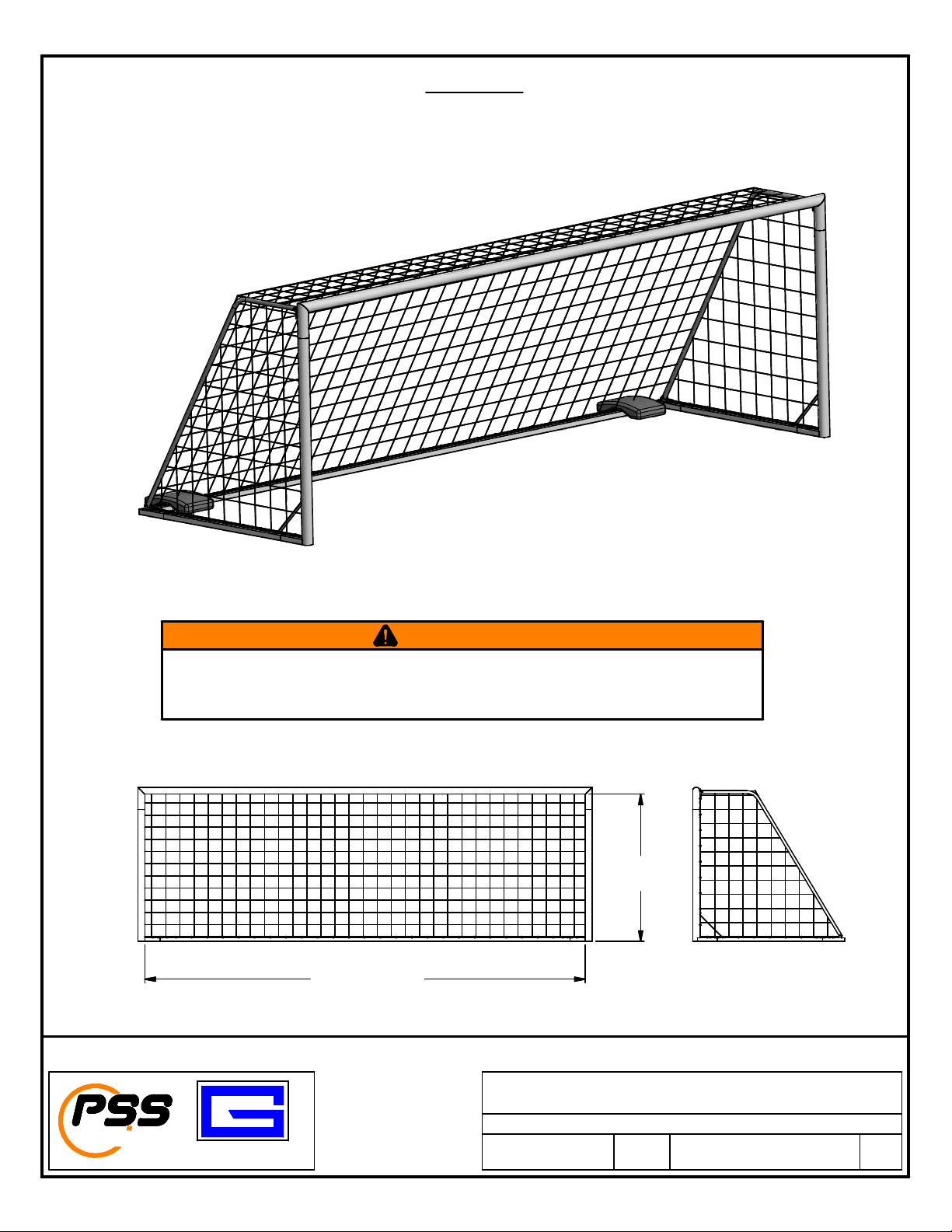
6'-6" X 12' 7' X 21' 8' X 24'
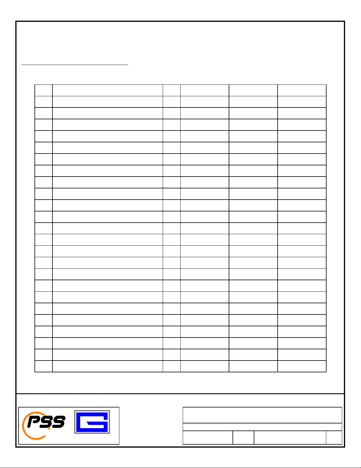
Item Description QTY SGRD612SPT SGRD721SPT SGRD824SPT
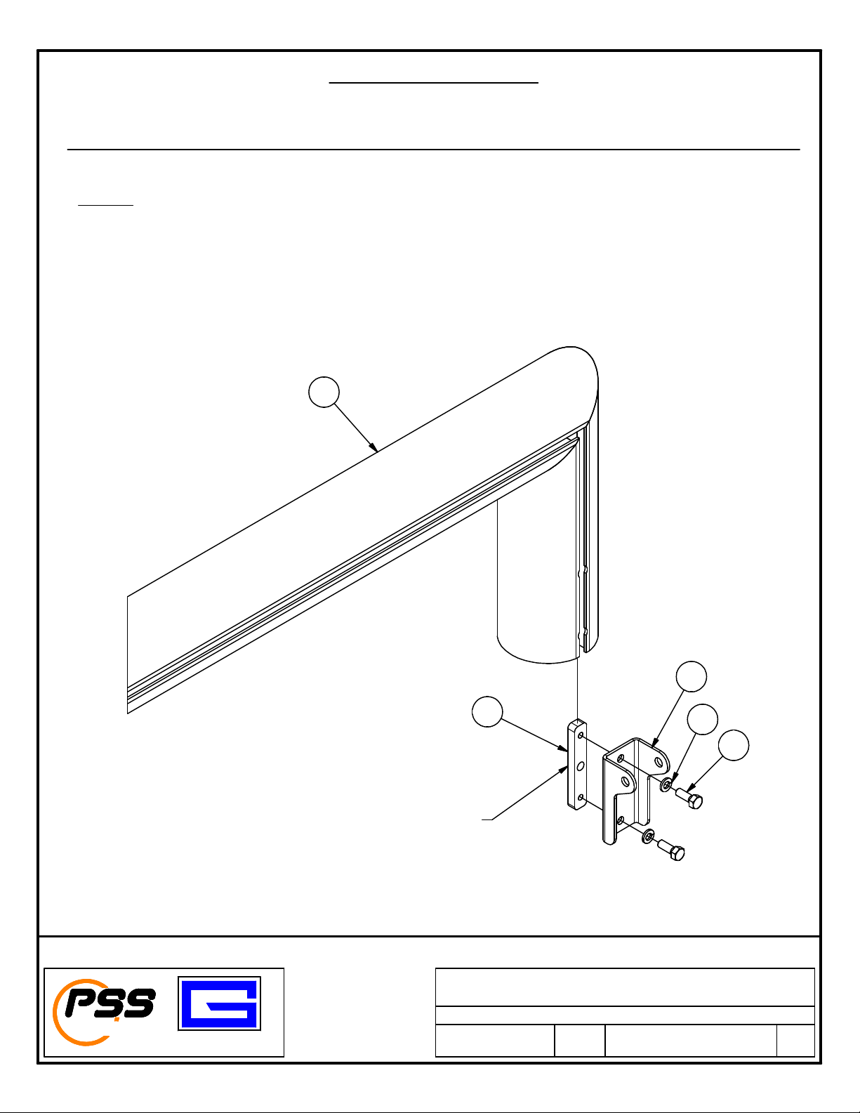
1 NET, SOCCER 1 SN612-3W SN721-4W SN824-4W
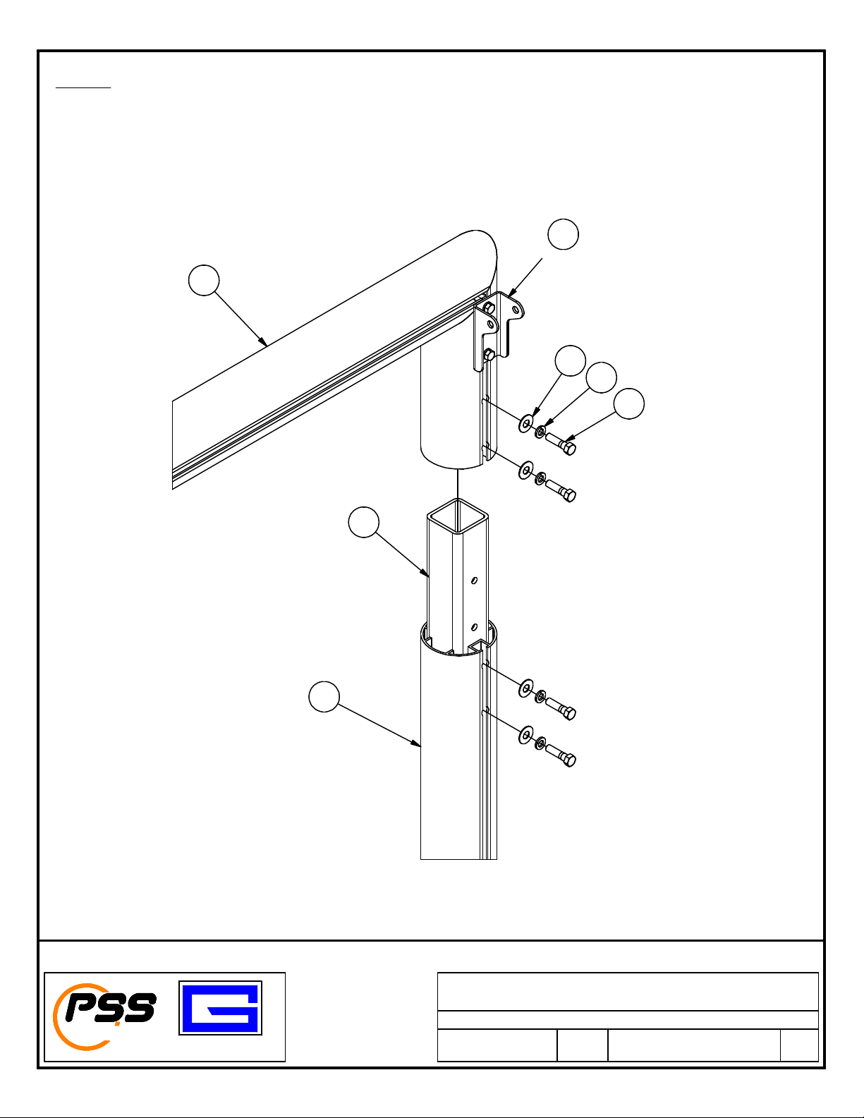
2 CROSSBAR WELDMENT 1 655755863 655755836 655755839
3 SIDE STRIKER GOAL WELDMENT 2 655752343 656242115 655752329
4 CONNECTING TUBE - 4" ROUND SOCCER 2 655755201 655755201 655755201
5 STRIKER BASE OST 2 655752346 655752326 655752331
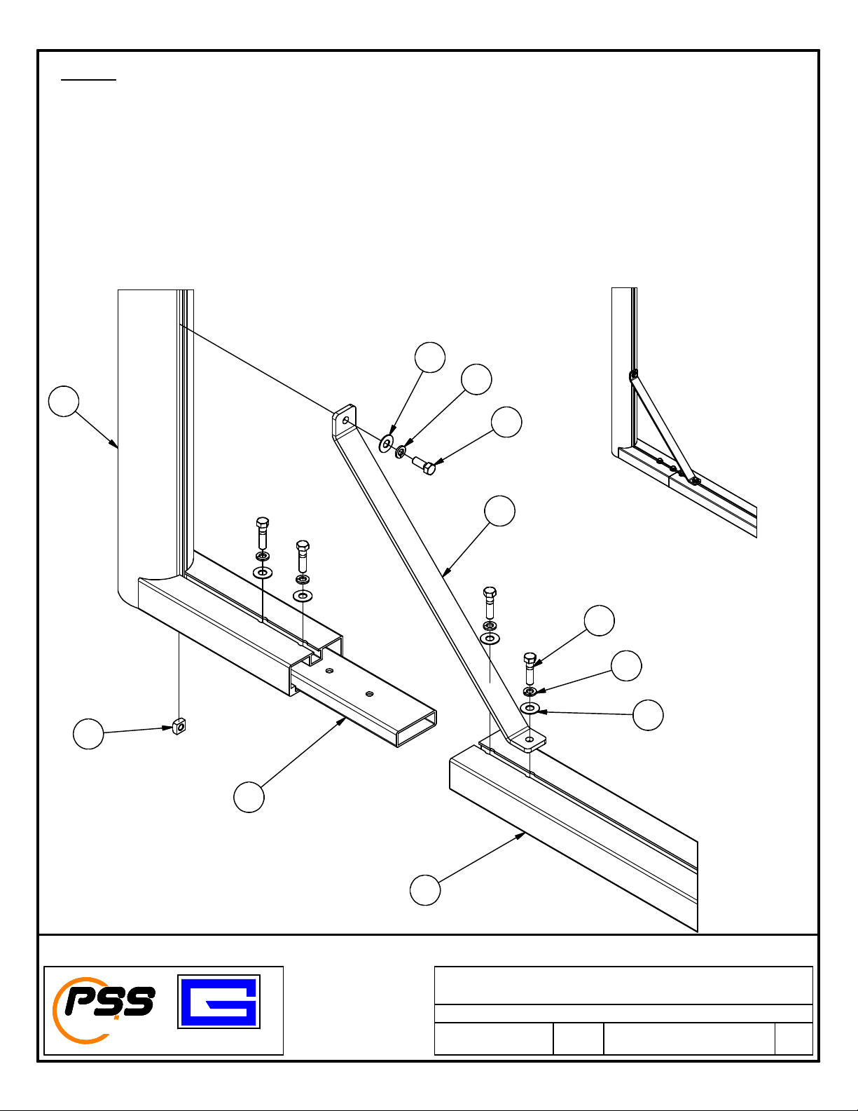
6 BRACE, GOAL FRAME 2 655752307 655752307 655752307
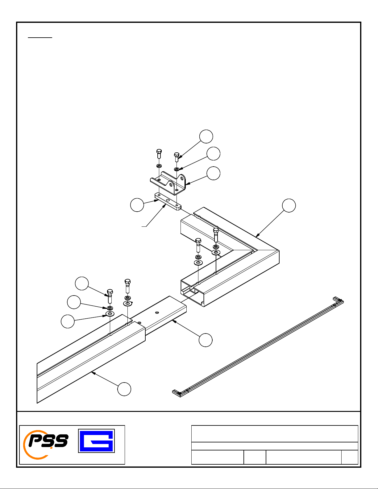
7 CONNECTING TUBE, 2" X 4" RECT GOALS 6 655755203 655755203 655755203
8 CORNER BRACKET 2" X 4" RECT GOALS 2 655752107 655752107 655752107
9 BACKSTAY 2 655752344 655752327 601652332
10 CROSSBAR RECT 1 655752109 655752111 655752112
11 BRACKET, BACKSTAY ATTACHMENT HD 4 656202416 656202416 656202416
12 CLAM LATE, NARROW (11/16" W) 4 656202106 656202106 656202106
13 HEX BOLT, 5/16-18 UNC X 0.875 SS 8 502-5-18-14SS 502-5-18-14SS 502-5-18-14SS
14 HEX BOLT, 3/8-16 UNC X 1 SS 2 502-6-16-16SS 502-6-16-16SS 502-6-16-16SS
15 HEX BOLT, 3/8-16 UNC X 1.5 SS 32 502-6-16-24SS 502-6-16-24SS 502-6-16-24SS
16 HEX BOLT, 3/8-16 UNC X 2.75 SS 4 502-6-16-44SS 502-6-16-44SS 502-6-16-44SS
17 HEX NUT, NYLON LOCK 3/8-16 SS 4 545-6-16SS 545-6-16SS 545-6-16SS
18 SQUARE NUT 3/8-16 SS 2 546-6-16SS 546-6-16SS 546-6-16SS
19 FLAT WASHER 3/8 STAINLESS STEEL 42 561-6SS 561-6SS 561-6SS
20 S LIT LOCK WASHER 5/16 SS 8 562-5SS 562-5SS 562-5SS
21 S LIT LOCK WASHER 3/8 SS 34 562-6SS 562-6SS 562-6SS
22 NET CLI (50 ER BAG) 100 651652567 651652567 651652567
23 SOCCER WT BAG W/ HANDLE 4 SGSB SGSB SGSB
TM
GARED
PERFORMANCE
SPORTS SYSTEMS
Gared Holdings, LLC
9200 E. 146th St.
Noblesville, IN 46060
FILE LOC.
SHT. NO. PART NO. REV
PORTABLE ROUND FRAME STRIKER GOAL
3
OF 14
651752116
Q:\Inventor Files\
DATE
3/14/2018
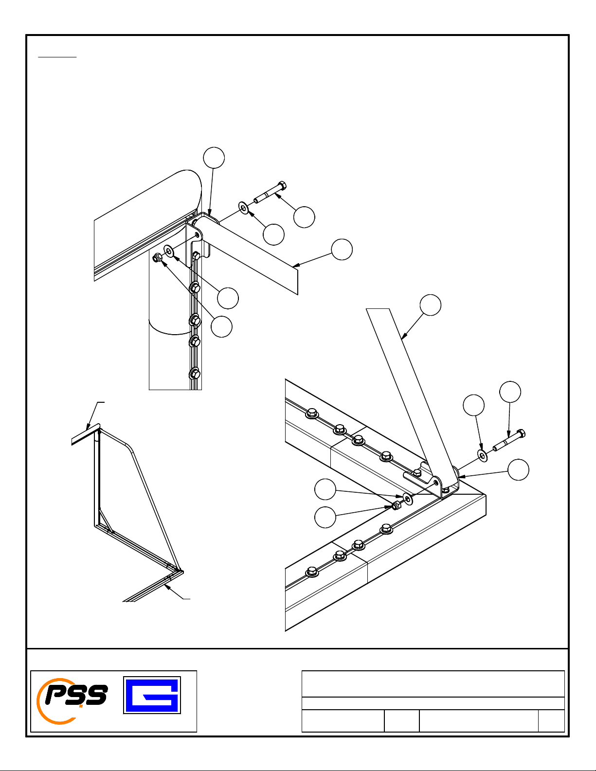
Installation and Assembly Instructions
Parts Checklist
Verify all parts listed on the packing list are present prior to installation.
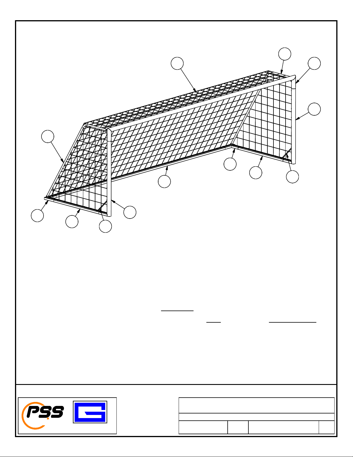
Soccer Goal frame components
Check the chart for the proper parts that match the Goal P/N received.