Gared Sports OmniSteel 5100 Manual

Model: 5100
OmniSteel™ Volleyball System
Installation, Operation and Maintenance Instructions
Please read all instructions before attempting installation or operation of these units
SAVE THESE INSTRUCTIONS FOR FUTURE USE
P
UBLICATION
N
O
.
6 0 1 7 5 5 4 1 7

5100 OmniSteel™ Volleyball System
1
Table of Contents
Section Page No.
Introduction 2
Parts Checklist 3
Floor Sleeve Installation 4-5
Floor Cover Installation 6
Net Installation Instructions 7-9
Maintenance and Check Sheet 10

5100 OmniSteel™ Volleyball System
2
Introduction
Thank you for your purchase of a Gared Sports OmniSteel™ Volleyball System. To
ensure that our equipment will provide years of use to you, we are including this installation,
operation, and maintenance guide. This guide will provide information on the proper assembly
and installation methods, operating procedures, and preventative maintenance of your volleyball
system.
Please note that a Bill of Materials is being included with this guide. Please check that all
of the parts called out on the Bill of Materials are present prior to beginning assembly and setup.
Please do not substitute for factory parts. Please contact the PSS or Gared Sports customer
service department and allow them to determine if substitute parts are acceptable.
It is recommended that an individual who has been properly trained perform the
installation operation of the volleyball system.
To prevent normal wear and tear from shortening the life of the unit, preventative
maintenance inspections and repairs should be performed at least once per year. If the units are
subject to high or unusual usage, inspections should be scheduled to occur more frequently. If
items are found to be nonconforming, replacements can be ordered from PSS or Gared Sports or
one of our authorized dealers. When contacting PSS or Gared Sports, please have information
regarding the dealer/installer who sold the unit, the name of the project, and any applicable
warranty information
PARTS LIST BY SUB ASSEMBLY
PART NO. DESCRIPTION QTY.
6252 CABLE COVER SET 1 EACH
6404 FLOOR SLEEVE 3-1/2” O.D. X 9.0” TALL 2 EACH
1028-22-00 NET ANTENNA 1 PAIR
6430 6” BRASS FLOOR COVER 2 EACH
5106 3” STEEL VOLLEYBALL WINCH POST 1 EACH
5107 3” STEEL VOLLEYBALL END POST 1 EACH
7607-22-00 NET SIDELINE MARKER 2 EACH
601654708 VOLLEYBALL NET 1 EACH
Note: Number 6404 & 6430 are normally shipped early.
Sleeve and floor covers are shipped early to be installed at time of
original construction. Posts are shipped fully assembled.

5100 OmniSteel™ Volleyball System
3
Set-up Guide
Parts Checklist
Verify all parts listed on packing list are present prior to installation.
Floor Sleeves/Covers Plates (These may ship early and separately)
-Floor Sleeves OK
-Cover Plates OK
Upright Posts (Refer to drawings or pictures in the instructions)
-End Post(s) OK
-Winch Post(s) OK
Net/Cable Hardware
-Cable OK
-Winch (es) & Hardware OK
-Antenna(s) OK
-Net(s) OK
Padding
-Upright Pads OK
-Chain & Cable Covers OK
Optional Accessories
-Referee Stand OK
-Equipment Cart OK
-Storage Devices OK

5100 OmniSteel™ Volleyball System
4
Floor Sleeve Installation
1. Mark (2) spots on the floor exactly 36 feet apart (refer to most recent set of architectural
prints for exact locations within the gym). These represent the CENTERS of each sleeve
installation. If sleeves are to be more or less than 36 feet apart, contact a PSS or Gared
representative for information regarding this alteration.
2. Cut (2) round holes 5” in diameter through the playing surface and centered on the spots
marked in step one. (See pages 8 & 9)
3. After cutting out the circle in the surface flooring, cut a similar hole in the concrete slab
below. The diameter of this hole should also be 5”, however the size is not critical. The
hole must be large enough to accommodate the sleeve with room for grout.
4. When drilling the hole in concrete, the slab must be fully penetrated. Under the slab,
hollow out (by hand) an area about 16-20 inches deep from the playing surface. The hole
should be about 6 to 8 inches deeper than the bottom of the sleeve once it is inserted.
(See page 8)
5. It is recommended that a “non-shrink” grout be used to anchor the sleeve. Pour the grout
mixture into the hole until it is just below the BOTTOM of the concrete hole. Cover the
sleeve during installation to prevent debris from falling into it or grout from entering
bottom of sleeve.
6. Insert the 3 1/2” O.D. sleeve and work it down into the grout until the inside bottom of
the sleeve is 11” below the TOP surface of the floor. Incorrect sleeve depth will result in
a net height error. Make sure the sleeve is vertical, perpendicular to the playing surface.
(See page 5)
7. Wait a minimum of (7) days to allow the grout to cure before setting up the posts.
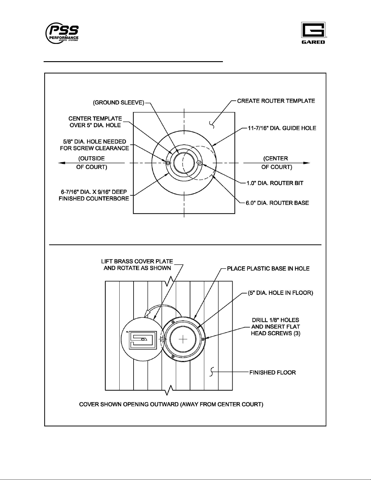
8. Using a router and template, make a counterbore 6-7/16” diameter by 9/16” deep
centered over the original 5.0” hole in the floor, to receive the brass floor cover
with plastic base. A template can be made from a piece of Masonite or thick
plastic. Make a hole in the template material so that when the router is used with
it, the counter bore achieves a good fit. Many router bit and template
combinations are possible. A skilled woodworker will be needed for this
operation! A finished counterbore of 6-7/16” diameter is what is important!
Practice on a piece of scrap wood first. If the hole is too big, corrections may not
be possible. (see page 6)
9. Install the floor covers. Place floor covers; drill holes and install screws as shown.
(see page 6)

5100 OmniSteel™ Volleyball System
5
Installation Instructions for Ground Sleeves

5100 OmniSteel™ Volleyball System
6
Counterbore Details and Floor Cover Installation

5100 OmniSteel™ Volleyball System
7
Net Installation Instructions
1. Lift and rotate brass floor covers out of the way. Insert the winch post and end post.
2. Remove adjustment pin to change height of upper telescopic tubes. Reinsert at the desired
playing height. Heights are marked for men’s and women’s play.
3. Begin attaching the net by placing the top net cable over the support pulley of the End
Post and attaching it to the steel hook as shown on page 8.
4. Next, wrap the other end of the cable over the support pulley of the Winch Post and
down to the winch. Attach the end of the cable to the hook on the winch drum as shown
on page 9. Turn the winch handle clockwise to tighten the net. Turn the handle counter-
clockwise to loosen the net.
5. The height of the net will vary with the tightness of the cable. Minor height adjustments
can be made by screwing the foot pads on the bottom of the posts in or out. (Posts must
be removed from the floor sleeves to make these adjustments).
6. Center the net on the cable. There should be the same amount space between the net and
the posts at each end. Now attach the upper and lower net straps. Undo the Velcro straps
as they come shipped with the net. Wrap the straps around the end posts and through the
rectangular steel rings as shown in the illustration. Pull straps tight and press the Velcro
surfaces together. (see illustration below). These straps are responsible for maintaining
the net tension and should be adjusted as required. Expect stretch in the net.
Details - End Post with Net

5100 OmniSteel™ Volleyball System
8
Details – Winch Post with Net

5100 OmniSteel™ Volleyball System
9

5100 OmniSteel™ Volleyball System
10
Maintenance
1. General inspection of equipment when used should be performed to ensure no
catastrophic failures have occurred during the course of use between yearly
inspections.
2. It is recommended that yearly inspections be conducted to determine if any bolts
or any other hardware has become worn or loosened. A sample check sheet has
been provided for you in this guide.
3. During yearly inspections, all moving parts should be inspected while in
operation. Key points to look for include rotation points where bushings contact
metal, winches, and pulleys.
4. Any loose bolts or nuts should be tightened.
5. Check sliding components and straps for wear.
Maintenance Check Sheet
Date: Unit: .
Anchors/Floor Sleeves
-Anchors/bolts OK Repair Replace
-Floor sleeves/covers OK Repair Replace
Unit Supports / Brackets / Hinges
-Tubes; dents, stress spots, etc. OK Repair Replace
-Bolts; loose, deformed, etc. OK Repair Replace
-Brackets/Hinges; bent, not rotating, etc.
OK Repair Replace
Winch/Strap
-Winch; binding, loose, etc. OK Repair Replace
-Hardware; Quick links OK Repair Replace
Sliding Components
-Locking Mechanisms OK Repair Replace
Safety Padding
-Velcro Function OK Repair Replace
-Vinyl Condition OK Repair Replace
Replacement parts and / or service to the equipment can be obtained from your local PSS or
Gared dealer or installer. To find your local PSS or Gared dealer, visit us online or contact
customer service department at the web address or phone number listed on the last page of this
manual.

Gared Holdings, LLC
Performance Sports Systems Gared Sports
9200 E. 146
th
Street 707 North 2
nd
Street
Noblesville, IN 46060 St. Louis, MO 63102
800-848-8034 800-325-2682
www.perfsports.com www.garedsports.com
Table of contents
Other Gared Sports Accessories manuals
Popular Accessories manuals by other brands

Enerlites
Enerlites MWOS installation instructions

EMX Industries, Inc.
EMX Industries, Inc. IRB-RET operating instructions

Spectris
Spectris Bruel & Kjaer Vibro 8315 Instruction

VOLTCRAFT
VOLTCRAFT PB-19C operating instructions

PCB Piezotronics
PCB Piezotronics M105C12 Installation and operating manual

PCB Piezotronics
PCB Piezotronics IMI SENSORS 640B12 Installation and operating manual