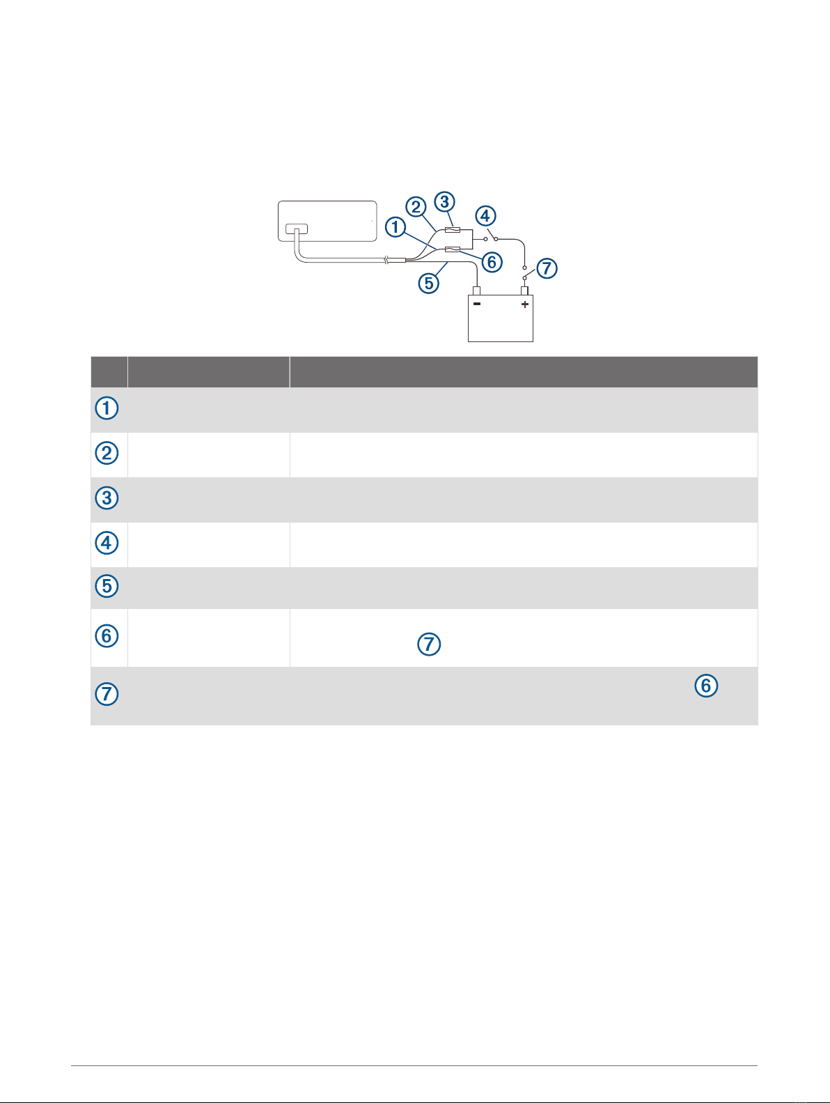
Garmin Fusion Apollo MS-RA670 User manual

Apollo™MS-RA670 Installation Instructions
Important Safety Information
WARNING
Failure to follow these warnings and cautions could result in personal injury, damage to the vessel, or poor
product performance.
See the Important Safety and Product Information guide in the product box for product warnings and other
important information.
This device must be installed according to these instructions.
Disconnect the vessel's power supply before beginning to install this product.
Before applying power to this product, make sure it has been correctly grounded according to these
instructions.
CAUTION
To avoid possible personal injury, always wear safety goggles, ear protection, and a dust mask when drilling,
cutting, or sanding.
NOTICE
When drilling or cutting, always check what is on the opposite side of the surface to avoid damaging the vessel.
Do not use the stereo as a template when drilling the mounting holes because this may damage the glass
display and void the warranty. You must only use the included template to correctly drill the mounting holes.
You must read all installation instructions before beginning the installation. If you experience difficulty during
the installation, contact Fusion® Product Support.
What's In the Box
• Mounting gasket
• Four 8-gauge, self-tapping screws
• Two screw covers
• Power and speaker wiring harness
• Auxiliary-in, line-out, and subwoofer-out wiring harnesses
• 2 m (6 ft.) NMEA 2000® drop cable
• Dust cover
Tools Needed
• Phillips screwdriver
• Electric drill
• Drill bit (size varies based on surface material and screws used)
• Rotary cutting tool or jigsaw
• Silicone-based marine sealant (optional)
GUID-980DCA16-A168-4346-A761-1B2786A5DD83 v5July 2021

Mounting Considerations
• You must mount the stereo on a flat surface that provides open airflow around the rear of the stereo for heat
ventilation.
• If you are installing the stereo in a location that may be exposed to water, you must mount it within 45
degrees of the horizontal plane.
• If you are installing the stereo in a location that may be exposed to water, add a drip loop to the cable to
allow water to drip off of the cable and avoid damage to the stereo.
• If you need to mount the stereo outside a boat, you must mount it in a location far above the waterline, where
it is not submerged, and where it cannot be damaged by docks, pilings, or other pieces of equipment.
• To avoid interference with a magnetic compass, you must install the stereo at least 20 cm (7.87 in.) away
from a compass.
2 Apollo MS-RA670 Installation Instructions

Mounting the Stereo
NOTICE
Do not use the stereo as a template when drilling the mounting holes because this may damage the display and
void the warranty. You must only use the included template to correctly drill the mounting holes.
Be careful when cutting the hole to mount the stereo. There is only a small amount of clearance between the
case and the mounting holes, and cutting the hole too large could compromise the stability of the stereo after it
is mounted.
Do not apply grease or lubricant to the screws when fastening the stereo to the mounting surface. Grease or
other lubricants can cause damage to the stereo housing.
Before you can mount the stereo in a new location on the mounting surface, you must select a location in
accordance with the mounting considerations.
1Adhere the template to the mounting surface.
2Drill a hole inside the corner of the dashed line on the template.
3Cut the mounting surface along the inside of the dashed line on the template.
4Ensure the mounting holes on the stereo line up with the pilot holes on the template.
5Using an appropriately sized drill bit for the mounting surface and screw type, drill the pilot holes.
6Remove the template from the mounting surface.
7Complete an action:
• If you are installing the stereo in a dry location, place the included mounting gasket on the back of the
stereo.
• If you are installing the stereo in a location that is exposed to water, apply silicone-based marine sealant
on the mounting surface around the cutout.
NOTICE
Do not install the included mounting gasket if you applied sealant to the mounting surface. Using sealant
and the mounting gasket may reduce water resistance.
8If you will not have access to the back of the stereo after installation, make the necessary wiring
connections.
9Secure the stereo to the mounting surface using the included screws .
You should hand-tighten the screws when securing the stereo to the mounting surface to avoid over
tightening them.
10 Snap the screw covers in place .
Connection Considerations
For the stereo to function correctly, you must connect it to power, to speakers, and to input sources. You should
carefully plan the layout of the stereo, speakers, input sources, optional NMEA 2000 network, and optional
Fusion PartyBus™ devices or network before making any connections.
Apollo MS-RA670 Installation Instructions 3

Port Identification
Item Description
Connects the stereo to the wiring harness for zone 3.
Connects the stereo to the wiring harness for auxiliary input 1, and for the line and
subwoofer outputs for zones 1 and 2.
Connects the stereo to the power and speaker wiring harness.
FUSE Contains the 15 A fuse for the device.
USB Connects the stereo to a USB source.
SXM TUNER
Connects the stereo to a SiriusXM® Connect Tuner to receive SiriusXM stations where
available (not included).
Connects to a Fusion DAB module to receive DAB stations where available (not included).
DIGITAL AUDIO IN
(OPTICAL) Connects the stereo to an optical digital audio source, such as TV or DVD player.
ETHERNET Connects the stereo to another Fusion PartyBus stereo, zone stereo, or network (Fusion
PartyBus Networking, page 13).
ANTENNA
Connects the stereo to a typical AM/FM antenna.
If you are installing the stereo on a boat with a metal hull, you must use a ground-
dependent antenna. If you are installing the stereo on a boat with a non-metal hull, you
must use a ground-independent antenna. See the installation instructions provided with
your antenna for more information.
NMEA 2000 Connects the stereo to a NMEA 2000 network (NMEA 2000 System Wiring Diagram,
page 12).
4 Apollo MS-RA670 Installation Instructions

Wiring Harness Wire and Connector Identification
Wire or RCA Connector
Function
Bare Wire Color
or RCA Label
Name
Notes
Ground (-) Black Connects to the power source (Power Connection,
page 7).
Power (+) Yellow Connects to the power source (Power Connection,
page 7).
Ignition Red Connects to the power source (Power Connection,
page 7).
Amplifier on Blue
Connects to optional external amplifiers, enabling them to
turn on when the stereo turns on.
A connected amplifier must use the same ground (-) as the
stereo for this signal wire to function correctly.
Telemute Brown
Activates when connected to ground.
For example, when you connect this wire to a compatible,
hands-free mobile kit, the audio mutes or the input
switches to AUX when a call is received and the kit
connects this wire to ground. You can enable this function
ality from the settings menu.
Dim Orange
Speaker zone 1 left (+) White
Speaker zone 1 left (-) White/black
Speaker zone 1 right (+) Gray
Speaker zone 1 right (-) Gray/black
Speaker zone 2 left (+) Green
Speaker zone 2 left (-) Green/black
Speaker zone 2 right (+) Purple
Speaker zone 2 right (-) Purple/black
Zone 1 line out (left)
Zone 1 line out (right) ZONE 1 Provides output to an external amplifier, and is associated
with the volume control for zone 1.
Apollo MS-RA670 Installation Instructions 5

Wire or RCA Connector
Function
Bare Wire Color
or RCA Label
Name
Notes
Zone 1 subwoofer out ZONE 1 SUB
OUT
Each subwoofer cable provides a single mono output to a
powered subwoofer or subwoofer amplifier.
Zone 2 line out (left)
Zone 2 line out (right)
Zone 2 subwoofer out
ZONE 2
ZONE 2 SUB
OUT
Provides output to an external amplifier, and is associated
with the volume control for zone 2.
Each subwoofer cable provides a single mono output to a
powered subwoofer or subwoofer amplifier.
Auxiliary in left
Auxiliary in right AUX IN Provides an RCA stereo line input for audio sources, such
as a CD or MP3 player.
Zone 3 line out (left)
Zone 3 line out (right)
Zone 3 subwoofer out
ZONE 3
Provides output to an external amplifier, and is associated
with the volume control for zone 3.
Each subwoofer cable provides a single mono output to a
powered subwoofer or subwoofer amplifier.
6 Apollo MS-RA670 Installation Instructions

Power Connection
When connecting the stereo to power, you must connect the yellow, red, and black wires to the power source.
The yellow and red wires have different functions, and the method you use to connect them to power depends
on how you plan to use the stereo on your vessel.
Yellow wire
• This wire provides power to the stereo.
• This wire should be connected through a 15 A circuit breaker, if one is available on the vessel.
NOTICE
If a 15 A circuit breaker is not available on the vessel, you must connect this wire to power through a 15 A
fuse (not included).
• This wire provides power to the stereo at all times, and it will drain the battery even when the stereo is not
in use. You should install a manual switch on this wire if a 15 A circuit breaker is not available on the
vessel, or if you cannot toggle the breaker to remove power to the stereo when storing the vessel.
• If it is necessary to extend this wire, use 14 AWG (2.08 mm2) wire. For extensions longer than 1 m (3 ft.),
use 12 AWG (3.31 mm²) wire.
Red wire
• This wire can be connected to the same power source as the yellow wire through the ignition or through a
manual switch. This enables you to turn the stereo on and off automatically when you turn the vessel on
and off, or when you activate the switch.
• Using this wire to turn the stereo on and off behaves in the same way as using the power button on the
stereo to turn it on and off. It is not necessary to connect this wire to a switch if you plan to toggle the
power using the power button on the stereo or using a connected chartplotter or remote control. This wire
must be connected to turn the stereo on.
• When you turn off the stereo using this switch or the power button, it enters a standby mode that allows
the stereo to start up again faster than if you switch the power off using the yellow wire. When it is in
standby mode, the stereo uses up to 200 mA, and you must turn off power to the stereo on the yellow wire
thorough the circuit breaker or manual switch when you are not using the vessel to avoid draining the
battery.
•NOTICE
You must connect this wire to power through a 1 A fuse (not included), whether or not you connect it to
the ignition or manual switch.
• If it is necessary to extend this wire, use 22 AWG (0.33 mm2) wire.
Black wire
• This is the ground wire, and you must connect it to the negative terminal of the power source or to a
common ground.
• If it is necessary to extend this wire, use 14 AWG (2.08 mm2) wire. For extensions longer than 1 m (3 ft.),
use 12 AWG (3.31 mm²) wire.
Apollo MS-RA670 Installation Instructions 7

Connecting to Power Without Using an Ignition Switch
This method of connection is used most often on larger vessels and on vessels with multiple networked
stereos and other marine devices. For these installations, a faster startup time is typically less critical, and it is
more effective to use the breaker or a dedicated switch on the electrical panel to turn off the stereo and ensure
that no unexpected power drain occurs.
1Consult this diagram to plan the wire connections.
Item Description Notes
Yellow wire You should connect this wire to the red wire before you connect both
wires to the manual switch or circuit breaker.
Red wire You should connect this wire to the yellow wire so that it does not act as a
physical standby switch.
1 A fuse (not included) You must install this fuse on the red wire before you connect the red wire
to the yellow wire.
Manual switch
(optional)
This switch is needed only if a circuit breaker is not available or if it
provides a more convenient method of cutting power to the stereo.
Black wire Ground (-)
15 A fuse (not included)
This fuse is required if you are not able to connect to power through a
15 A circuit breaker .
15 A circuit breaker If a circuit breaker is not available, you must connect a 15 A fuse on
the yellow wire
2Route all wires to the stereo wiring harness, the circuit breaker or switch, and the power source as
necessary.
Do not connect the wiring harness to the stereo until after you have made all of the bare wire connections.
3Install all of the necessary fuses on the red and yellow wires.
4Connect the wiring harness to the stereo.
When the circuit breaker or manual switch is closed, the stereo is always on. You can use the power button on
the stereo or a connected chartplotter or remote control to place the stereo in a low-power standby mode if
needed.
NOTE: When you are not using the vessel, you should remove power to the stereo using the circuit breaker or
manual switch to avoid draining the battery.
8 Apollo MS-RA670 Installation Instructions

Connecting to Power Through an Ignition Switch
This method of connection is used most often on ski boats, wake boats, and similar sport or recreational
vessels where power to the engines is toggled often. For these installations, a quick standby and faster startup
time is desired so that music can be stopped and begin playing again as quickly as possible after restarting the
engines. When in standby mode, the stereo uses up to 200 mA, and you should connect the power wires
through a circuit breaker or manual switch to avoid draining the battery when you are not using the boat.
1Consult this diagram to plan the wire connections.
Item Description Notes
Yellow wire You must connect this wire to the same power source as the ignition or
ACC switch.
Red wire You must connect this wire to the ignition or ACC switch before you
connect it to the same power source as the yellow wire.
1 A fuse (not included) You must install this fuse on the red wire before you connect the red wire to
the ignition or ACC switch.
Ignition or ACC switch
Connecting the red wire to this switch allows the stereo to enter a low-
power standby mode when you turn off the engines, so it can start up faster
when you turn on the engines again.
Black wire Ground (-)
15 A fuse (not
included)
This fuse is required if you are not able to connect to power through a 15 A
circuit breaker .
15 A circuit breaker or
manual switch
If a circuit breaker is not available, you must connect a 15 A fuse on the
yellow wire. You should also connect the yellow wire to power using a
manual switch, so you can remove power to the stereo when you are not
using the boat.
2Route all wires to the stereo wiring harness, the ignition or ACC switch, the circuit breaker, and the power
source as necessary.
Do not connect the wiring harness to the stereo until after you have made all of the bare wire connections.
3Install all of the necessary fuses on the red and yellow wires.
4Connect the wiring harness to the stereo.
When you turn on the ignition switch, the stereo turns on along with other accessory electronics. When you turn
off the ignition switch, the stereo enters a low-power standby mode.
NOTE: When you are not using the vessel for an extended period of time, you should remove power to the
stereo using the circuit breaker or other manual switch on the yellow wire to avoid draining the battery.
Apollo MS-RA670 Installation Instructions 9

Speaker Zones
You can group speakers in one area into a speaker zone. This enables you to control the audio level of the
zones individually. For example, you could make the audio quieter in the cabin and louder on deck.
Up to two pairs of speakers can be connected per channel of each zone, in parallel. One zone can support no
more than four speakers using the on-board amplifier.
Zones 1 and 2 are powered by the on-board amplifier. Zone 3 is available as a line-level output only. To use the
RCA line output and the RCA subwoofer output for zone 3, you must connect an external amplifier.
You can set the balance, volume limit, tone, subwoofer level, subwoofer frequency, and name for each zone,
and configure other zone-specific settings.
Single-Zone System Wiring Example
Speakers
Water-tight connection
10 Apollo MS-RA670 Installation Instructions

Speaker System Wiring Using a Line Out
This diagram illustrates a system installation with an external amplifier and subwoofer connected to zone 2 on
the stereo using a line out. You can connect an amplifier and subwoofer to any or all of the available zones on
the stereo.
NOTE: You can connect speakers to the speaker wires for the internal stereo amplifier while using the line out
on zones 1 and 2, although adjusting the volume affects both the speakers connected to the internal amplifier
and the line out. This may result in uneven volume levels.
Zone 1 speakers
Water-tight connection
Zone 2 speakers
Amplifier-on signal wire
You must connect this wire to each amplifier connected to a zone line out.
A connected amplifier must use the same ground (-) as the stereo for this signal wire to function
correctly.
Powered amplifier connected to the zone 2 line out
Zone 2 line out and subwoofer out
Each subwoofer cable provides a single mono output to a powered subwoofer or subwoofer amplifier.
You may need to use an RCA splitter to connect this to an amplifier.
Subwoofer
Connecting a SiriusXM Tuner Module
This device is compatible with a SiriusXM SXV300 or newer vehicle tuner module.
1If you have already connected a USB source, disconnect it from the stereo.
2Connect the cable from the SiriusXM tuner module to the SXM TUNER port on the back of the stereo.
3Follow the instructions provided with the SiriusXM tuner module and antenna to complete the SiriusXM
installation.
4If necessary, reconnect the USB source.
5Complete the stereo installation.
Apollo MS-RA670 Installation Instructions 11

NMEA 2000 System Wiring Diagram
Stereo
Supported chartplotter, MFD, or compatible Fusion NMEA 2000 remote control
NMEA 2000 GPS antenna, speed sensor, or wind instrument.
When the stereo is connected to the same NMEA 2000 network as a compatible engine, a GPS antenna,
a chartplotter with a built-in GPS antenna, a wind instrument, or a water speed sensor, it can be config
ured to automatically adjust the volume according to the engine RPM, the speed over ground, the wind
speed, or the speed through water. See the stereo Owner's Manual for more information.
In-line switch
NMEA 2000 power cable
NMEA 2000 drop cable, up to 6 m (20 ft.)
9 to 16 Vdc power supply
NMEA 2000 terminator or backbone cable
NMEA 2000 T-connector
NMEA 2000 terminator or backbone cable
12 Apollo MS-RA670 Installation Instructions

Configuring an Optional Wired NRX Remote Control
NOTICE
The stereo is configured by default to work with a NMEA 2000 network, and the NRX POWER option should be
enabled only when an optional wired NRX remote control is connected directly to the stereo. Enabling this
option when the stereo is connected to a NMEA 2000 network may damage other devices on the NMEA 2000
network.
If you connect an optional wired NRX remote control directly to the stereo, and not through a NMEA 2000
network, additional configuration is needed.
1Select > SETTINGS > POWER OPTIONS.
2Select an option:
• If you connected both your stereo and your optional wired remote to a NMEA 2000 network, make sure
the NRX POWER option is not selected. This enables the optional remote to receive power from the
NMEA 2000 network.
• If you connected the optional wired remote directly to the stereo through the NMEA 2000 connector,
select the NRX POWER option. This enables the stereo to supply power to the optional remote.
Fusion PartyBus Networking
The Fusion PartyBus networking feature allows you to connect multiple compatible stereos together on a
network, using a combination of wired or wireless connections.
You can group a compatible stereo, such as the Apollo RA670 stereo, with other compatible stereos connected
to the network. Grouped stereos can share available sources and control media playback on all of the stereos
in the group, which allows for a synchronized audio experience across the vessel. You can quickly create, edit,
and break up groups as needed from any compatible stereo or remote control on the network.
NOTE: A zone stereo, such as the Apollo SRX400, can create or join a group to control and play sources from
other stereos, but it cannot share its sources with the group.
For additional considerations when sharing sources, see the owner's manual.
You can use compatible stereos and remote controls, whether they are grouped or not, to adjust the volume of
the available speaker zones for any stereo on the network.
Wired Networking Considerations
When you are planning your network installation, observe the following considerations for all wired
connections.
• You must connect devices using standard Cat5e or Cat6 network cables with RJ45 connectors.
• You can use one network cable to directly connect two compatible devices.
• You must use wired network switches and wired or wireless network routers when you connect more than
two compatible devices to a network.
• If you install a router on the network, it should be configured to be a DHCP server by default. See your router
instructions for more information.
• If you do not install a router, and there are no other DHCP servers on the network, you should configure one
Fusion PartyBus stereo to be a DHCP server.
Apollo MS-RA670 Installation Instructions 13

Wired Network Example for Direct Connections
No network setting changes are needed when connecting two devices together directly, but for the best results,
you should configure one device to be a DHCP server.
Fusion PartyBus stereo
Fusion PartyBus zone stereo or remote control
Wired Network Example with a Switch or Router
You must use wired network switches, a wired network router, or both to connect more than two devices.
If you did not install a router, and there are no other DHCP servers on the network, you should configure one
Fusion PartyBus stereo to be a DHCP server. If you installed a router, you may need to configure it to be a DHCP
server. See your router instructions for more information.
Fusion PartyBus stereo
Wired network switch or wired network router
Fusion PartyBus zone stereo or remote control
14 Apollo MS-RA670 Installation Instructions

Constructing a Network
You should have a basic understanding of networking when building a network for Fusion PartyBus devices.
These instructions guide you through the basics of building and configuring a network, and should apply to
most situations. If you need to perform advanced networking tasks, such as assigning static IP addresses to
devices on the network or configuring advanced settings on a connected router, you may need to consult a
networking professional.
1Determine the installation location of the Fusion PartyBus devices you want to connect to the network.
NOTE: Wired connections are more reliable than wireless connections. When planning your network, you
should run network cables instead of using wireless connections when possible.
2Determine the installation location of any needed network routers or switches.
3Route Cat5e or Cat6 network cable to the installation locations of the stereos, switches, and router.
4Connect the network cables to the stereos, switches, and router.
NOTICE
Do not completely install the stereos yet. You should test the network before you install the stereos.
5Turn on all devices connected to the network, including wireless devices.
6If you are using a network router (wired or wireless), consult the documentation provided with your router to
configure the router as the DHCP server, if necessary.
All stereos should use their default configuration (DHCP CLIENT).
7Test the network by selecting > GROUPS to view a list of devices connected to the on the network, and
select an option:
• If any devices are not available to the network, troubleshoot the network.
• If all devices are available to the network, complete the installation for each stereo, if necessary.
Network Troubleshooting
If you cannot see or connect to Fusion PartyBus devices on the network, check the following:
• Verify that only one device, either a stereo or a router, is configured as a DHCP server.
• Verify that all Fusion PartyBus devices, network switches, routers, and wireless access points are connected
to the network and turned on.
• Verify that wireless Fusion PartyBus devices are connected to a wireless router or wireless access point on
the network.
NOTE: Wired connections are more reliable than wireless connections. If possible, you should connect
devices to the network using an Ethernet cable.
• You may experience wireless interference if there are many nearby wireless access points. Change the
channel on your router or wireless access point to test for and correct interference.
• Connecting a Bluetooth® device to a stereo configured as a wireless access point or client may reduce
wireless performance. Disconnect Bluetooth devices to test for and correct interference.
• If you configured static IP addresses, verify that every device has a unique IP address, that the first three
sets of numbers in the IP addresses match, and that the subnet masks on every device are identical.
• If you have made configuration changes that might be causing networking issues, reset all network settings
to the factory default values.
Apollo MS-RA670 Installation Instructions 15

Stereo Information
Specifications
Weight 750 g (26.5 oz.)
Water rating IEC 60529 IPX6 and IPX7 (front of stereo only, when properly installed)1
Operating temperature range From 0 to 50°C (from 32 to 122°F)
Storage temperature range From -20 to 70°C (from -4 to 158°F)
Input voltage From 10.8 to 16 Vdc
Current (max.) 15 A
Current (muted) Less than 700 mA
Current (off) Less than 200 mA
Fuse 15 A mini blade-type
NMEA 2000 LEN @ 9 Vdc 1 (50 mA)
Bluetooth wireless range Up to 10 m (30 ft.)
ANT® wireless range Up to 3 m (10 ft.)
Wireless frequencies/protocols Bluetooth 2.4 GHz @ from 13.29 dBm nominal
ANT 2.4 GHz @ from 6.92 dBm nominal
Compass-safe distance 20 cm (7.87 in.)
On-board, Class D amplifier
Output music power per channel 4 x 70 W max. 2 ohm
Total output peak power 280 W max.
Output power per channel 4 x 43 W RMS at 14.4 Vdc input, 2 ohm, 10% THD2
4 x 26 W RMS at 14.4 Vdc input, 4 ohm, 10% THD2
Line output level (max.) 5.5 V (peak to peak)
Aux input level (typical) 1 V RMS
Tuner frequencies
Tuner Europe and Australasia USA Japan
FM radio frequency range 87.5 to 108 MHz 87.5 to 107.9 MHz 76 to 95 MHz
FM frequency step 50 kHz 200 kHz 50 kHz
AM radio frequency range 522 to 1620 kHz 530 to 1710 kHz 522 to 1620 kHz
AM frequency step 9 kHz 10 kHz 9 kHz
1 The device withstands incidental exposure to water of up to 1 m for up to 30 min, and is protected against powerful jets of water. For more information, go to
www.garmin.com/waterrating.
2 The stereo may limit the output power to prevent the amplifier from overheating, and to maintain the audio dynamics.
16 Apollo MS-RA670 Installation Instructions

Stereo Dimension Drawings
Side Dimensions
21 mm (0.83 in.)
102 mm (4.0 in.)
68 mm (2.68 in.)
49 mm (1.93 in.)
Top Dimensions
157 mm (6.18 in.)
130 mm (5.10 in.)
21 mm (0.83 in.)
10 mm (0.39 in.)
Software Updates
Go to support.garmin.com to find software updates and information for your device.
Apollo MS-RA670 Installation Instructions 17

物質宣言
部件名称
有毒有害物质或元素
铅汞镉六价铬多溴联苯 多溴二苯醚
印刷电路板组件
屏幕/背光
金属零件
电缆 电缆组件 连接器
本表格依据 SJ/T11364 的规定编制。
: 代表此种部件的所有均质材料中所含的该种有害物质均低于
(GB/T26572) 规定的限量
: 代表此种部件所用的均质材料中, 至少有一类材料其所含的有害物质高于
(GB/T26572) 规定的限量
*該產品說明書應提供在環保使用期限和特殊標記的部分詳細講解產品的擔保使用條件。
產品
© 2019–2021 Garmin Ltd. or its subsidiaries support.garmin.com
Table of contents
Other Garmin Marine Audio manuals

Garmin
Garmin FUSION XS Series User manual

Garmin
Garmin Fusion Apollo Series User manual

Garmin
Garmin FUSION MS-RA70 User manual

Garmin
Garmin Fusion MS-RA60 User manual

Garmin
Garmin Fusion Apollo RA770 User manual

Garmin
Garmin Fusion Apollo RA770 Instruction manual

Garmin
Garmin Fusion BB100 User manual

Garmin
Garmin Fusion APOLLO RV-RA770 User manual