Gas Data GFM 436 User manual

1
GFM 436

2
1.1 Document revision history ...............................................................................................................5
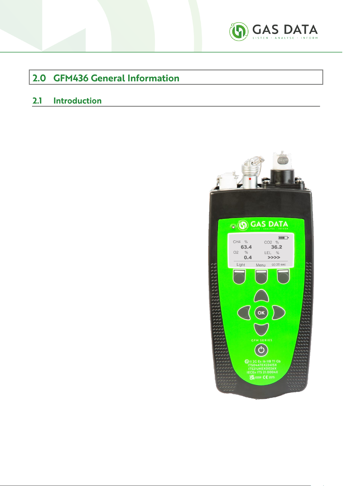
2.1 Introduction......................................................................................................................................6
Features..................................................................................................................................................6
2.2 Spares list..........................................................................................................................................7
3.1 Important safety related points .......................................................................................................9
4.1 Introduction to the GFM436 Functions and Features....................................................................10
4.2 GFM436 Instrument Specification .................................................................................................12
4.3 Specialist Functionality...................................................................................................................13
4.3.1 Lower Explosive Limit..................................................................................................................13
4.3.2 Managing hydrocarbons using the hexane channel ...................................................................13
4.3.3 PID Compensation Factor Prediction ..........................................................................................14
4.4 Third Party Approvals.....................................................................................................................15
4.4.1 ATEX.............................................................................................................................................15
5.1 Optional Extra Accessories.............................................................................................................17
6.1 Starting Up......................................................................................................................................18
6.2 Navigating the Screens of the GFM436..........................................................................................20
6.3 Starting Up......................................................................................................................................21
6.4 Taking a Gas Measurement............................................................................................................22
6.4.1 Connecting the gas sample pipe .................................................................................................22
7.1 Gas Display Two..............................................................................................................................25
8.1 Connecting the gas flow pipe.........................................................................................................27

3
8.2 Taking a Static Pressure (SP) Measurement..................................................................................30
9.1 Gas velocity Measurement with optional vane anemometer .......................................................32
10.1 Gas Temperature Measurement with optional temperature probe...........................................34
10.2 DIP Meter Reading .......................................................................................................................35
11.1 Gas Temperature Measurement with optional temperature probe...........................................36
12.1 Sample Point Setup ......................................................................................................................37
12.2 Logging Setup ...............................................................................................................................40
12.3 View reading display.....................................................................................................................40
12.4 Clock Display.................................................................................................................................43
12.5 Store Menu...................................................................................................................................44
12.6 User Calibration............................................................................................................................45
12.7 Auto Turn Off................................................................................................................................45
Low battery warning ............................................................................................................................46
Batteries ...............................................................................................................................................46
Changing the gas filter..........................................................................................................................48
User calibration display........................................................................................................................49
Logging setup........................................................................................................................................54
Logging display .....................................................................................................................................57
Hazardous areas classified by zones ....................................................................................................62
Different types of gas ...........................................................................................................................62
Design and construction of intrinsically safe instruments for use in flammable atmospheres ..........63
Testing and certification.......................................................................................................................64

4
Different types of gas ...........................................................................................................................65
Important notes ...................................................................................................................................65
Response Time .....................................................................................................................................66
Technical data –MiniAir 6 Micro .........................................................................................................66
Cleaning and maintenance...................................................................................................................66
General handling tips ...........................................................................................................................67
Cleaning instructions............................................................................................................................67
Conditions and exclusions....................................................................................................................70
Disposal ................................................................................................................................................70

5
Issue: A
Revision: 2
Date: 24/11/2022
ISSUE
REV
DATE
REVISION DESCRIPTION
A
1
19/12/2013
Initial Release
A
2
28/11/2022
Brand Update
6
The Gas Data GFM436 handheld series of analysers is designed specifically for monitoring and analysing gas
content of landfill, biogas and contaminated land sites. It measures the methane, oxygen and carbon dioxide
content of site gases, gas pressure or vacuum, and gas velocity.
Operation is extremely simple, yet the readings obtained are
highly accurate. The instrument uses Gas Data's proprietary
infra-red methane and carbon dioxide sensors and a
combination of industry standard electrochemical gas sensor
cells. A variety of external sensors can be plugged in, e.g. vane
anemometer to measure gas velocity or a temperature probe
for ambient and other temperatures.
The GFM436 series has rechargeable Nickel Metal Hydride
batteries giving around eight hours use between charges. A
battery charger and mains unit is supplied with the instrument
and a field replaceable battery pack is also available as an
optional extra.
Features
•Up to 7 gas analysis channels.
•4 Wavelength optical infra-red analyser.
•Atmospheric pressure.
•Powerful sample pump.
•User replaceable sample filter.
•Field replaceable/rechargeable battery pack.
•Optional flow, pressure and temperature.

7
Category
Description
GD order code
Filter
GFM External Filters 25mm
18810
GFM Internal Filters 15mm
18811
GFM External Filters 50mm
18818
Connector
GFM/Click! Sample Pipe Connector (Male Metal)
18812
GFM Sample Pipe Connectors (Female)
18813
GFM/Click! Sample Pipe Connector (Male plastic)
18934
Calibration Check Gas - On Demand Flow Regulator C10 - Stainless Steel
18496
Tube
GFM Sample Pipe
17227
GFM43x Sample Tube
17226
GFM43x/610 Flow Tube
16480
Cable
GFM Temperature Probe Extension Cable - 1m
19425
Vane Anemometer
16502
Brass Temperature Probe
16503
Temp Expansion inc. Brass Probe
18730
T-Piece Temperature Probe
17220
USB Download cable
16501
Battery pack
16457
Universal DC In-Car Multi Voltage Power Adaptor
21266
AC Mains Battery charger
16455
Casing
Inlet housing
17204
Battery cover
17203
Leather cover
16781
Black carry case
16933
.

8
The Gas Data GFM has been designed to operate in typical field environments where flammable gases may be
present.
All ‘Special Conditions for Safe Use’ as detailed on the ATEX certificate (see Appendix F) must be adhered to.
The following points must be observed:-
•The instrument must be recharged in the non-hazardous area.
•The instrument must be checked for normal operation prior to carrying it into the hazardous
area:
oBEFORE entering a known hazardous zone, switch on the instrument and make sure
the display is visible and that the keys respond correctly.
oBEFORE entering a known hazardous zone, check that the sample pump can be
operated.
•The instrument must be inspected for damage prior to use and the instrument must not be
used if the case is damaged:
oBEFORE entering a known hazardous zone, check the instrument for damage. Pay
particular attention to the keyboard and aspirator.
•The instrument must be carried in the leather case to avoid the risk of electrostatic discharge:
oBEFORE entering a hazardous zone make sure that the instrument is securely enclosed
in its leather case.
_________________________________________________________________
Failure to comply the ‘Special Conditions for Safe Use’ can be potentially hazardous to the user and
others.
__________________________________________________________________
Warning

9
•The safest medium to sample a gas line with the instrument is to connect it to an isolated sample line,
accessible by a ball valve (or another suitable alternative).
•Sampled gas will be discharged from the ‘sample out’ port of the instrument at a rate of
approximately 500ml/min.
Make sure this gas will not create a hazardous zone worse than ZONE I See Appendix
B for full description of hazardous zones.
•Flush the instrument with clean air before sampling to prevent mixing potentially reactive mixtures of
gas within the instrument.
•Verify instrument calibration before and after use to minimise the risk of falsely determining an
atmosphere as hazardous or safe.
•Do not connect a GFM436 Series instrument to gas sources at greater than +50 mbar above
atmospheric pressure.
•Do not operate the GFM436 in ambient temperatures outside the range of -10 to +40 °C
•Do not attempt to dismantle the instrument. It contains no user replaceable parts.
•Do not operate the unit if it is damaged in any way (i.e. loose front panel, missing screws etc.).
•Do not connect or remove electrical connectors on the top of the instrument in the hazardous area.
•Do not use (i.e. power on) the instrument while charging.
•Only charge the batteries in a safe well-ventilated area using the charger supplied.
•Ensure correct filter is used on the Gas In port –If any doubt please contact Gas Data
•Use only Gas Data spares and accessories –See spares list.
For further information please refer to:
Error! Reference source not found.
Error! Reference source not found.
Gas Data cannot accept any liability for loss or damage due to its usage. Satisfy yourself
that the unit is suitable for the application that you intend to use it for. If in doubt about the suitability of a
GFM426 Series instrument for a particular application call Gas Data Ltd for further advice.

10
The Gas Data GFM436 is an ATEX accredited hand-held gas analyser designed specifically for monitoring
and analysing soil gas parameters in greenfield and brownfield (contaminated land) sites and landfill
sites.
It is lightweight, small and robustly manufactured in a weather resistant case making it suitable for use
even in challenging field applications. It measures the methane, carbon dioxide, oxygen, hydrogen
sulphide, hexane and carbon monoxide content of the gas sample. It also has internal sensors for the
measurement of gas pressures (or vacuum) and flow. External sensors can be attached for the
measurement of temperature and gas velocity.

11
Operation is extremely simple, yet the readings obtained are highly accurate. The instrument uses Gas
Data's proprietary infra-red methane and carbon dioxide sensors and a combination of industry
standard sensors for the other parameters.
The GFM436 has a rechargeable Nickel Metal Hydride battery pack giving around eight hours use
between charges. A universal input mains battery charger unit is supplied with the instrument.
Additional field replaceable battery packs and an in car 12V DC powered charger are also available as
optional extras.
To help conserve battery life, the GFM436 features an auto power off facility. It will switch itself off after
15 minutes if no keys are pressed or there is no USB communication activity. During unattended data
logging, it can be set to shut itself down after taking a sample and turn itself back on to take the next
sample. The instrument will also switch off if the battery voltage is too low for it to operate.
The GFM436 features data storage with three-layer alphanumeric labelling of sample points and
unattended data logging capability. Data is stored in non-volatile FLASH memory with a capacity of
approximately 3000 data sets including the time and date it was stored and a 32-character
alphanumeric label. Using Gas Data's SiteMan5 program data and labels can be transferred to and from
a PC via a USB connection cable.

12
General
Ex. Rating to:
II 2 G Ex ib IIB T1 Gb
Ambient Temp Range
-10 to 40 °C
Battery Life
8 hours typical
Battery Charge Time
2 to 4 hours
Aspiration Rate
300 ml/min typical
Storage Capacity
>3000 Readings
Protection Rating
IP65
Dimensions
200 x 100 x 60 mm
Weight
1 kg typical
GFM436 Channels
Range
Typical Accuracy
Typical Response
Methane
0 to 100% (0.1)
0.3% @ 5%, 3.0% @ 60%, 3.0% @
100%
20s
0 to 100% LEL (0.1)
4% LEL
30s
Carbon Dioxide
0 to 100% (0.1)
0.3% @ 5%, 3.0% @ 40%, 3.0% @
40%
20s
Oxygen
0 to 25% (0.1)
0.5%
20s
Atmospheric Pressure
800 to 1200 mbar
5 mbar, 1 mbar resolution
20s
H2S
2000 ppm (10.0)
5% of fs
30s
CO
2000 ppm (1.0)
5% of fs
30s
Static Pressure
-200mbar - +200mbar
+/- 1 mbar
10s
Flow Range
+100 to -60 l/hr
+/- 0.1l/hr to +/-3l/hr
10s
Flow Resolution
0.1 l/hr
Differential Pressure
+1250/-1250 Pa
+/-3Pa to +/- 250Pa
10s
Optional Channels
Temperature
-10 to 100c
+/-1.0c
60s
Gas Velocity
0-40 m/s
+/-0.51 m/s resolution
30s
Battery Charger, Carry Case, Sample Pipe, Manual, Calibration Certificate, Download Cable
Temperature Probe, Vane Anemometer

13
The GFM436 incorporates an additional Hexane calibration of the infra-red sensor which is used to
indicate, quantify and track hydrocarbon gases that would normally make the infra-red methane
calibration read excessively high or even over-range rendering the results meaningless. With the
GFM436 when and if the methane sensor shows an over-range signal or abnormally high methane value
(a good indicator that other hydrocarbons are present in the borehole) the hexane value will remain
valid and in range up to 2.000%.
This response range is chosen as it allows typical concentration levels of hydrocarbon vapours that
would be found in contaminated ground due to the spillage of common liquid fuels and oils to be
quantified on a standard scale as a percentage hexane vapour equivalent. The Hexane signal is taken
from the infra-red bench and processed to another output on the instrument display in the scale 0.000 –
2.000%.
It does not need additional gas calibration as the infra-red beam is normalised using the existing
methane calibration gas. At 100% Methane concentration the Hexane reading will be typically showing
0.200 –0.300% and will continue to rise if there is a hydrocarbon problem present. Laboratory sampling
is needed to establish a baseline and identify the specific hydrocarbon compound but repeat tests with
the GFM436 will allow trends to be determined with great consistency.
Using this technique, the Hexane reading can also be used for an immediate indication that remedial
action on the borehole has been successful or not. Boreholes can be re-measured knowing that readings
The instrument calculates and displays the Lower Explosive Limit (LEL) of Methane. This function is
intended for use where methane has become mixed with air i.e. where oxygen is still present in normal
atmospheric proportions with respect to atmospheric nitrogen. This is the worst case so if the gas sample
is taken from a location where the oxygen content is depleted e.g. due to biological demand, then the LEL
indication will be higher than expected.

14
are “in scale” by referencing the original readings taken. No more waiting for samples to come back
from the lab!
Boreholes across a site can be compared and peak readings established to indicate those of significant
interest, worst case and negligible etc.
The PID (Photo Ionisation Detector) is the instrument widely accepted by the industry to quantify other
hydrocarbon gases present in ground boreholes. It is a good choice of instrument as it is highly sensitive
to a broad range of hydrocarbon gases and it does not directly detect methane. It uses a UV light source
to ionise hydrocarbon gases in its sample cell so that they can be quantified using an electronic charge
amplifier. However, even small quantities of methane present in a borehole can absorb the UV light thus
quenching the ionisation and de-sensitising the instruments response leading to under measurement or
complete non-detection of any hydrocarbon gases present.
The built in PID Compensation factor in the GFM436 is a figure derived from extensive testing of the
non-linear characteristics of this phenomenon and is displayed on the GFM instrument as a number
between 1 and 10. This is used to multiply the PID reading to give an accurate total hydrocarbon value in
the borehole. This figure is accurate for the Ionscience Ltd Phocheck range of PIDs up to a value of 10
which occurs at approximately 9% methane in the borehole.

15
This characteristic varies between PID manufacturers. For example, typically only 5 –6% of methane will
diminish the PID response of a RAE Systems unit to only one tenth of the correct value thus needing a
PID compensation factor of 10. Instrument characteristics when subjected to high levels of methane do
differ considerably (see chart of typical responses below).
4.4.1
This instrument is ATEX Certified under normal operation.
ATEX accreditation is void under the following circumstance:
•If the instrument is removed from its leather case
•If the instrument is charging or plugged into a computer i.e. not under normal operation
•When the battery cover or inlet housing has been removed or unscrewed
For full information and details see Page 11 “Safe Use of the GFM4xx Series” and Appendix J “ATEX
Certification”.

16
The GFM436 series instruments are supplied in a fitted case containing the following items:
GFM4XX instrument
seseriesnstrinstrument
Battery charger
Vane
anemometer
(optional)
Spares kit
Gas pipe
Allen
key
Temperature
probe (optional)

17
Vane anemometer –Air velocity measuring
device. Instructions and information can be
found on Chapter 8.0 –Gas Velocity
Readings.
Brass Temperature Probe –Gas line
temperature measuring device. Instructions
and information can be found on Chapter
9.0 –Gas Temperature Readings.
In Car charger –additional power adapter,
available for purchase on request.
Gas Cylinder and demand flow regulator –
available for User Calibration.

18
When turned on the instrument will take a few seconds to boot up. During this time a “loading” banner
will be displayed.
After booting up the instrument commences a warmup period. This is to allow all the sensors to
initialise. During this period the letters “WRM” appear in the top right-hand corner of the display as
shown. Please wait until WRM disappears before proceeding.
Also in the top right-hand corner is the battery charge indicator. Three bars indicate fully charged, two
bars is three-quarters charged, one bar is half charged and no bars is quarter charged or less.

19
The screen also shows the instrument type (GFM436), its recalibration date and the serial number. If
you ever need to contact Gas Data for assistance with your instrument, please quote the serial number.
The Left Soft Key is labelled “Light” and will switch the Backlight on and off.
Pressing the Left or Right Arrow Key will take you to the Gas Display.

20
Other manuals for GFM 436
1
Other Gas Data Measuring Instrument manuals


