Ankersmid Sampling ABYSS User manual

Page 1 of 45
Ankersmid Sampling
Neerlandweg 21
Man
ual
ABYSS
Biog
as
Analy
zer
0
1
20
1
8
www.ankersmidsampling.com
© Reproduction of this document or its
c
ontent is not
allowed without permission of Ankersmid.
2610 Wilrijk
Belgium
info@ankersmid
sampling.com
Technical Details Subject to Change
.
Ankersmid Sampling
User Manual
ABYSS Infrared Gas Analyzer
for Biogas
Generation with modular Sensors (since 017)

Page 2 of 45
Ankersmid Sampling
Neerlandweg 21
Man
ual
ABYSS
Biog
as
Analy
zer
0
1
20
1
8
www.ankersmidsampling.com
© Reproduction of this document or its
c
ontent is not
allowed without permission of Ankersmid.
2610 Wilrijk
Belgium
info@ankersmid
sampling.com
Technical Details Subject to Change
.
0.1 Electrical standards
CE – Certification
The product described in this operating manual complies with following EC directives:
EMV-Instruction
The requirements of the EC directive 2004 108 EC “Electromagnetic compatibility“
are met.
Low Voltage Directive
The requirements of the EC directive 2006 95 EC “Low Voltage Directive“ are met.
The compliance with this EC directive has been examined according to DIN EN 61010.
Declaration of conformity
The EU Declaration of conformity is available at Ankersmid Sampling.

Page 3 of 45
Ankersmid Sampling
Neerlandweg 21
Man
ual
ABYSS
Biog
as
Analy
zer
0
1
20
1
8
www.ankersmidsampling.com
© Reproduction of this document or its
c
ontent is not
allowed without permission of Ankersmid.
2610 Wilrijk
Belgium
info@ankersmid
sampling.com
Technical Details Subject to Change
.
0. Safety instructions
Please read these operating instructions very carefully before start up and use of the
equipment.
Please check before installing the equipment if the device is suitable for:
- the exposed pressure
- the exposed temperature
- the exposed ambient conditions (e.g.: rain, moist, dust,…)
Attention must be paid to the requirements of IEC 364 (DIN VDE 0100) when
setting high-power electrical units with nominal voltages of up to 1000 V, together
with the associated standards and stipulations.
Work on electrical equipment should only be carried out by trained specialists.
Before connecting the equipment, be sure that the main voltage is equal to the
voltage mentioned on the type plate on the inside of he electrical box.
Beware that the apparatus and the control units are switched off before opening
of the protection body.
Installation, maintenance, monitoring and repairs can be done by authorised
personnel.
IMPORTANT
This equipment is, in its standard version, not explosion-proofed!
Safety marks are identified as follows:
DANGEROUS May cause serious human injuries
CAUTION May cause moderate human injuries or may
destroy the analyzer
ELECTRIC SHOCK May cause human injuries and/or may damage
the analyzer
FORBIDDEN
Not allowed in normal operation

Page 4 of 45
Ankersmid Sampling
Neerlandweg 21
Man
ual
ABYSS
Biog
as
Analy
zer
0
1
20
1
8
www.ankersmidsampling.com
© Reproduction of this document or its
c
ontent is not
allowed without permission of Ankersmid.
2610 Wilrijk
Belgium
info@ankersmid
sampling.com
Technical Details Subject to Change
.
0.3 Warranty
If the equipment fails, please contact your ANKERSMID SAMPLING dealer.
The warranty is covered for a period of 1 year countable from the first day of delivery (as
also specified in our normal terms and conditions of sale) when the apparatus is handled
and assembled correctly, installed according good craftsmanship, treatment and use or
operation of the equipment.
The warranty covers repair at the factory at no cost, or the replacement at no cost of the
equipment free ex user location. In case of resend or reshipment, the probe must be
properly packed or in his original protective packaging or in a sufficient adapted
recipient.
NOTE
Consumables are only covered by this warranty in case of production defaults.
Only the qualified personnel of the manufacturer are allowed to handle the cooling circuit
during the guarantee period.
The device must be in the original condition when guarantee claims are made.
0.4 Power supply
Depending on the type of cooler the device can be operated on alternating current of
115V 60Hz or 230V 50Hz.
Figure Standard flow chart of a gas sampling line
Diaphragm gas pump
Universal filter
Gas
cooler
Peristaltic pump for
condensate removal
Gas sample probe
Heated sample line
Analyser

Page 5 of 45
Ankersmid Sampling
Neerlandweg 21
Man
ual
ABYSS
Biog
as
Analy
zer
0
1
20
1
8
www.ankersmidsampling.com
© Reproduction of this document or its
c
ontent is not
allowed without permission of Ankersmid.
2610 Wilrijk
Belgium
info@ankersmid
sampling.com
Technical Details Subject to Change
.
1.1 Overview
NOTE
Before using the analyzer and its accessories, please familiarize yourself with
its operation by reading this manual. If you have any questions, please do not
hesitate to contact with us for assistance.
1. Receipt and storage of goods
Inspect the shipping boxes for any sign of damage. Damaged shipping boxes increase
the risk to find damaged material too.
The device is pre-installed. Possible accessories are packed in the same box but not put
together in any case.
The arrived goods should be carefully unpacked as soon as possible in order to control
the good and correct condition.
Remove the accessories as power cable and rack mounting lugs from the shipping box.
Carefully remove the analyzer from its shipping box together with its protections.
Remove the protections and place the material on a flat surface in a clean and dry
location. Inspect the material for any sign of damage.
The goods and the delivery note should be compared. If any difference is noted please
contact your Ankersmid Sampling contact person.
The delivery should be checked for any transport damage. If any anomaly is noted,
please contact the transport insurer immediately notifying of the damage.
The goods should be stored in a frost-protected area.
NOTE
Keep the shipping box and the protective packaging for eventual future
shipping needs.
1.3 Reporting Damage
If there are any apparent damages to the outside of the instrument due to shipping or
handling, file a damage claim and notify the forwarder immediately. The shipping
container or packing materials should be retained for inspection by the forwarder.

Page 6 of 45
Ankersmid Sampling
Neerlandweg 21
Man
ual
ABYSS
Biog
as
Analy
zer
0
1
20
1
8
www.ankersmidsampling.com
© Reproduction of this document or its
c
ontent is not
allowed without permission of Ankersmid.
2610 Wilrijk
Belgium
info@ankersmid
sampling.com
Technical Details Subject to Change
.
1.4 Before using the analyzer
NOTE
The use of the analyzer requires a full understanding of the analyzer
operation. Use the analyzer only as specified in this manual, otherwise its
good operation and initial performances may be impaired.
Authorized service representatives and original parts must only be employed in carrying
out repairs to the analyzer in order to maintain the validity of the warranty. Modification
of components, use of non-original parts, or use of incomplete or used parts will also
invalidate the warranty.
· Make sure there is no obstruction at the sample inlet before you operate the analyzer.
· The sample gas must be free from particles (< 1μ), oil traces and its moisture content
· Use only original parts that have been specifically designed for your analyzer. The use
of other parts than original ones may modify the performances of your analyzer.
· We also recommend configuring the auto zero-function in order to make the zero drift
negligible. Please refer to the specific sections of this manual.
· Do not expose the analyzer to electrical shock and or severe continuous mechanical
shock.
· Do not attempt to disassemble, adjust, or service the analyzer unless instructions for
that procedure are contained in the manual and or that part is listed as a replacement
part.
· Do not allow liquids to condense or use high power sprays on the instrument.
· The warranty will be voided if customer personnel or third parties damage the analyzer
during repair attempts. Non-authorized repair service attempts void this warranty.
IMPORTANT
The sample gas must be free from particles (< 1μ), oil traces and its moisture
content, if not, the manufacturer can provide portable or on line gas
conditioning system.
Repair/service cannot executed by non-authorized and/or non-qualified
people.
Figure Flow chart

Page 7 of 45
Ankersmid Sampling
Neerlandweg 21
Man
ual
ABYSS
Biog
as
Analy
zer
0
1
20
1
8
www.ankersmidsampling.com
© Reproduction of this document or its
c
ontent is not
allowed without permission of Ankersmid.
2610 Wilrijk
Belgium
info@ankersmid
sampling.com
Technical Details Subject to Change
.
1.5 Preparation for installation
The safety rules and regulations for the prevention of accidents must be observed when
carrying out the installation.
This device is to be used in only in VERTICAL position. The device is mountable on the
wall or panel.
The device has to be placed in a ventilated area, away from heat sources and magnetic
fields. If the equipment is placed outside, beware that it is prevented against rain, dust,
frost, and direct sunlight.
The Analyser must be installed on a flat surface (if used as bench-type analyser) or
integrated in a gas analysis cabinet. Avoid locations where the analyzer can be exposed
to vibrations, chocks or intense electromagnetic fields as this can have a negative effect
on the performances of the analyzer. Do not expose the analyzer to strong artificial light
or sun radiations, wind, moisture of rain. Prevent dust and moisture to enter the analyzer
otherwise its good operation will be
impaired.
IMPORTANT
A standard version of the device is not an explosion-proofed apparatus!
The layout of the device guarantees problem-free integration into the analysis systems.
NOTE
Ensure unhindered cooling air circulation while installing. Do not install
directly above possible sources of heat.
Install frost-free when used in winter and with adequate ventilation when
used in summer. Avoid direct solar radiation.
Do not drain condensate into the sewage system.
Sample gas condensate is a special waste that should not be drained in the public
sewage system or in water bodies. Guidelines as regards the condensate disposal as per
the Water Resources Act (WHG) must be adhered to.
System and process-specific safety measures must be followed before start-up!
Requirements of VDE 0100 as well their relevant standards and guidelines
must be followed while setting up high-voltage devices with rated voltages of
up to 1000V! The power supply circuit of ACC must be equipped with a fuse
compatible with the rated current (over-current protection). Electrical
specifications can be inferred from the technical specifications.

Page 8 of 45
Ankersmid Sampling
Neerlandweg 21
Man
ual
ABYSS
Biog
as
Analy
zer
0
1
20
1
8
www.ankersmidsampling.com
© Reproduction of this document or its
c
ontent is not
allowed without permission of Ankersmid.
2610 Wilrijk
Belgium
info@ankersmid
sampling.com
Technical Details Subject to Change
.
1.6 Mounting
The 19”-rack mount device should only be used in stationary conditions, the portable
device can be used on site, both with correct selection of the installation point and safe
installation. When used and properly installed in the prescript area ANKERSMID
SAMPLING guarantee a long-time of maintenance-free and satisfaction use.
Before switching ON the analyzer always check the gas inlet and outlet tubing are
correctly connected to the respective ports of the analyzer.
Sample gas pressure must be within the specification range in order to avoid gas leak
due to excessive pressure or wrong operation of the gas analyzer. A leakage of toxic or
explosive gas can lead to serious accident.
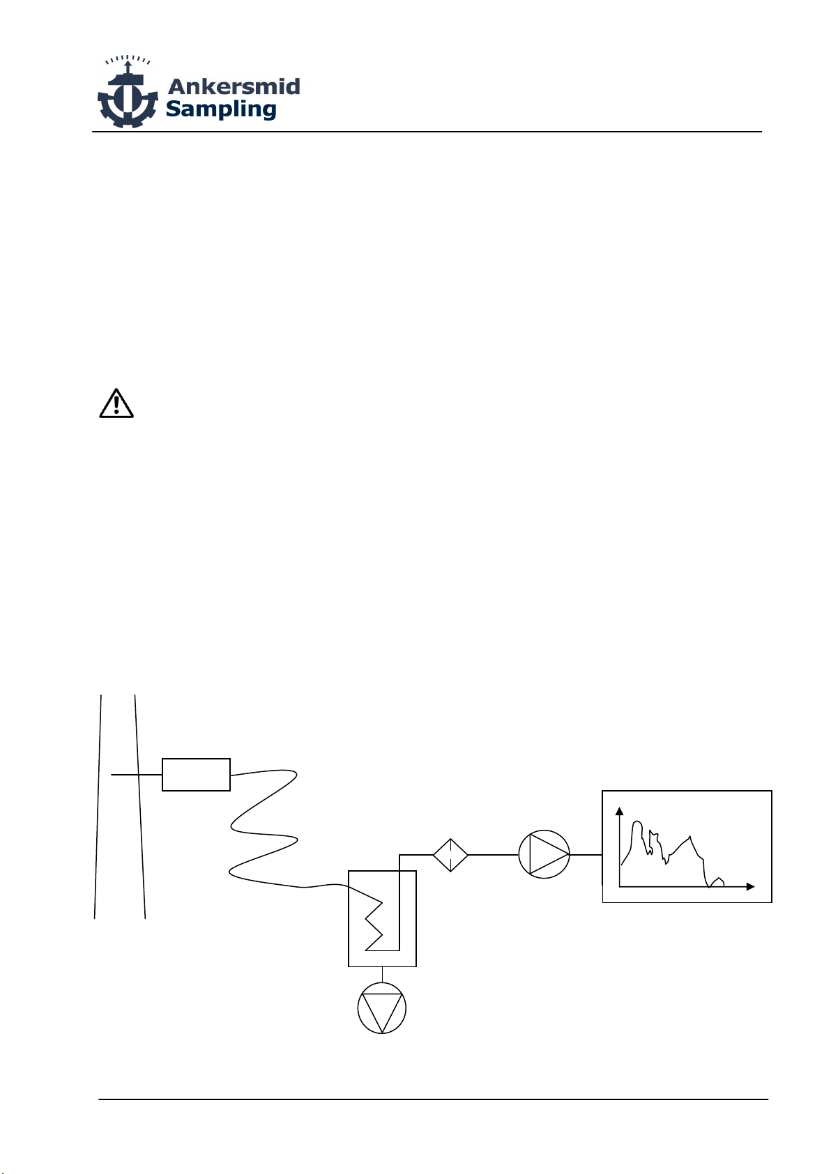
Sampling gas path should be based on the specific circumstances and make gas
conditioning device or system, otherwise it will cause the instrument does not work
properly.
Do not use the piping, pressure reducing valve or other sampling devices with grease
which may block the gas path or cause a fire.
Please use the power supply that complies with the power ratings of the analyzer, to
avoid fire and or abnormal operation.
Ensure the power supply is switched OFF when connecting the gas analyzer to the
process to avoid any accident by electric discharge.
Ground connection of the analyzer must be carried out according to the local and or
international regulations to prevent from any damage of injuries.
Ensure the power supply is switched OFF before connecting a data transmission line to
the serial RS232 port.
Insulation of all electrical connections and cables must be controlled before switching ON
the analyzer to avoid any dangerous and accidental electrical discharge.
NOTE
Test the gas analyzer response exclusively on target gases with certified gas
canisters from known concentration.
Span gas concentration need to be within 90% to 100% of the designed full scale range,
otherwise the accuracy and linearity of the analyzer can be affected. Use pure nitrogen
N2 5.0 quality for zero calibration.
Never let the moisture enter the analyzer to avoid electric discharge and risk of short
circuit.
Always prevent dust and oil traces for entering the analyzer to avoid damages to the
measuring cells.
Never switch OFF & ON successively the analyzer power supply without reasons,
otherwise the analyzer lifetime might be shortened, or the analyzer might be damaged.
Do not touch the input and output terminal site by metal and fingers etc..
Otherwise, it may result in electric shock
Smoking nearby to the analyzer is not allowed and could lead to serious fire hazards
Do not allow moisture intrusion analyzer. Otherwise, it may result in electric shock or
analyzer internal fire.

Page 9 of 45
Ankersmid Sampling
Neerlandweg 21
Man
ual
ABYSS
Biog
as
Analy
zer
0
1
20
1
8
www.ankersmidsampling.com
© Reproduction of this document or its
c
ontent is not
allowed without permission of Ankersmid.
2610 Wilrijk
Belgium
info@ankersmid
sampling.com
Technical Details Subject to Change
.
.1 Front and rear panels – Stationary Analyzer

Page 10 of 45
Ankersmid Sampling
Neerlandweg 21
Man
ual
ABYSS
Biog
as
Analy
zer
0
1
20
1
8
www.ankersmidsampling.com
© Reproduction of this document or its
c
ontent is not
allowed without permission of Ankersmid.
2610 Wilrijk
Belgium
info@ankersmid
sampling.com
Technical Details Subject to Change
.
. Alarm output
.3 RS 3 and DB9 interface connection

Page 11 of 45
Ankersmid Sampling
Neerlandweg 21
Man
ual
ABYSS
Biog
as
Analy
zer
0
1
20
1
8
www.ankersmidsampling.com
© Reproduction of this document or its
c
ontent is not
allowed without permission of Ankersmid.
2610 Wilrijk
Belgium
info@ankersmid
sampling.com
Technical Details Subject to Change
.
DANGER
The analyzer is not designed for use in areas with explosion risk.
Do not install the analyzer in a hazardous zone with presence of explosive gas.
Instrument installation (stationary 19”-rack version)
1. The stationary analyzer is delivered in a 19’’3U-rack enclosure and can be used as
bench type for desk installation or for integration in an instrumentation cabinet.
2. The analyzer enclosure is not rated for outdoor use.
3. The gas venting must be done outside of the building directly in the atmosphere.
4. Please avoid strong vibrating or magnetic disturbing.
5. Please select an environment with fresh air.
6. If used as desk type analyzer, please put the analyzer on a robust and plane support.
7. Power supply: 230V 50Hz (others on request)
8. Operating temperature: 0 to 50°C max.
9. Operating moisture: 5 to 85% RH, no condensation is allowed.
10. Dimension: rack 19’’3U:
width × length × height=433mm × 420mm × 132mm
11. Weight: 10 to 16 kg depending on the configuration.

Page 12 of 45
Ankersmid Sampling
Neerlandweg 21
Man
ual
ABYSS
Biog
as
Analy
zer
0
1
20
1
8
www.ankersmidsampling.com
© Reproduction of this document or its
c
ontent is not
allowed without permission of Ankersmid.
2610 Wilrijk
Belgium
info@ankersmid
sampling.com
Technical Details Subject to Change
.
.4 Front and rear panels – Portable Analyzer
Portable analyzer
1 --- LCD 1 --- Flow Meter
2 --- RS232 output 2 --- Spare use 1
3 --- Power Supply Socket (DC12. V) 3 --- Spare use 2
4 --- Operation button 4 --- Sampling gas inlet port
5 --- Sampling gas outlet port
--- Filter
.4.1 AC/DC adapter
The portable analyzer is supplied with an external AC DC adapter generating an output
voltage of 12.6 VDC3A.
This adapter is required to recharge the internal battery of the analyzer.
With a fully charged battery pack, the autonomy of the analyzer is at least 4 hours in
operation mode and 10h in standby mode.
The analyzer has a function for setting the activation of the backlight of the LCD.
To increase battery life, the LCD backlight time should be set appropriately for the use of
the analyzer. A permanently illuminated display reduces the battery life.

Page 13 of 45
Ankersmid Sampling
Neerlandweg 21
Man
ual
ABYSS
Biog
as
Analy
zer
0
1
20
1
8
www.ankersmidsampling.com
© Reproduction of this document or its
c
ontent is not
allowed without permission of Ankersmid.
2610 Wilrijk
Belgium
info@ankersmid
sampling.com
Technical Details Subject to Change
.
3.1.1 Technical data - 19”-rack version
Specifications
Measurement CO
2
, CH
4
, O
2
, H
2
S
Calculation High heating value or low heating value in MJ m3 or kcal m3
Gas flow 0.7 - 1.2 l min, external flow meter with needle valve
Pressure of gas inlet < 1bar
Sampling gas requirement Remove water vapor, dust (<1um) and oil
Response time <10s (NDIR)
Warm-up time 15 min
Interface RS232 (real time and memory data download software
included)
Output 4 - 20mA (can be customized)
Technology
CO
2
, CH
4
: proprietary dual-beam NDIR detectors
H
2
S: ECD
O
2
: galvanic fuel cell method
Display LCD 240 x 128 with back-light function
Simultaneous indication of the 7 measures and units
Programmable auto-zero function,
incl. internal pump, relay and solenoid valve
Data logging
Up to 1500 sets of data; logging rate adjustable from 3 to 99
sec
Possibility to identify 10 different sites and up to 100
measuring points
Operating temperature 0 to +50°C
Relative humidity 5 - 85%
Ambient air pressure 86 – 108kPa
Power supply 230V 50Hz
Dimension 483mm x 373mm x 140mm (W x L x H)
Weight ± 12Kg
Gas Method Range Resolution Precision T90
CO
2
NDIR 0-50%, 0-100% 0,1% ≤2% FS <10s
CH
4
NDIR 0-100% 0,1% ≤2% FS <10s
H
2
S ECD 0-5000ppm, 0-10000ppm 1ppm ≤3% FS <30s
O
2
Fuel cell 0-25% 0,01% ≤3% FS ≤2%
Version Part number Gas components
ABYSS BioGas 700 ABG 700 CO
2
+CH
4
+H
2
S+O
2
ABYSS BioGas 600 ABG 600 CO
2
+CH
4
+H
2
S
ABYSS BioGas 500 ABG 500 CH
4
+CO
2
+O
2
ABYSS BioGas 400 ABG 400 CH
4
+CO
2
ABYSS BioGas 300 ABG 300 CH
4
+H
2
S
ABYSS BioGas 200 ABG 200 CH
4
+O
2
ABYSS BioGas 100 ABG 100 CH
4

Page 14 of 45
Ankersmid Sampling
Neerlandweg 21
Man
ual
ABYSS
Biog
as
Analy
zer
0
1
20
1
8
www.ankersmidsampling.com
© Reproduction of this document or its
c
ontent is not
allowed without permission of Ankersmid.
2610 Wilrijk
Belgium
info@ankersmid
sampling.com
Technical Details Subject to Change
.
3.1. Technical data - Portable version
Specifications
Measurement CO
2
, CH
4
, O
2
, H
2
S
Calculation High heating value or low heating value in MJ m3 or kcal m3
Gas flow 0.7 - 1.2 l min, external flow meter with needle valve
Pressure of gas inlet < 1bar
Sampling gas requirement Remove water vapor, dust (<1um) and oil
Response time <10s (NDIR)
Warm-up time 15 min
Interface RS232 (real time and memory data download software
included)
Output 4 - 20mA (can be customized)
Technology
CO
2
, CH
4
: proprietary dual-beam NDIR detectors
H
2
S: ECD
O
2
: galvanic fuel cell method
Display LCD 240 x 128 with back-light function
Simultaneous indication of the 7 measures and units
Programmable auto-zero function,
incl. internal pump, relay and solenoid valve
Data logging
Up to 1500 sets of data; logging rate adjustable from 3 to 99
sec
Possibility to identify 10 different sites and up to 100
measuring points
Operating temperature 0 to +50°C
Relative humidity 5 - 85%
Ambient air pressure 86 – 108kPa
Power supply 230V 50Hz
Autonomy of > 4h with pump in operation
Dimension 380mm x 140mm x 225mm (W x L x H)
Weight ± 5Kg
Gas Method Range Resolution Precision T90
CO
2
NDIR 0-50%, 0-100% 0,1% ≤2% FS <10s
CH
4
NDIR 0-100% 0,1% ≤2% FS <10s
H
2
S ECD 0-5000ppm, 0-10000ppm 1ppm ≤3% FS <30s
O
2
Fuel cell 0-25% 0,01% ≤3% FS ≤2%
Version Part number Gas components
ABYSS BioGas 700P ABG 700P CO
2
+CH
4
+H
2
S+O
2
ABYSS BioGas 600P ABG 600P CO
2
+CH
4
+H
2
S
ABYSS BioGas 500P ABG 500P CH
4
+CO
2
+O
2
ABYSS BioGas 400P ABG 400P CH
4
+CO
2
ABYSS BioGas 300P ABG 300P CH
4
+H
2
S
ABYSS BioGas 200P ABG 200P CH
4
+O
2
ABYSS BioGas 100P ABG 100P CH
4

Page 15 of 45
Ankersmid Sampling
Neerlandweg 21
Man
ual
ABYSS
Biog
as
Analy
zer
0
1
20
1
8
www.ankersmidsampling.com
© Reproduction of this document or its
c
ontent is not
allowed without permission of Ankersmid.
2610 Wilrijk
Belgium
info@ankersmid
sampling.com
Technical Details Subject to Change
.
3. Gas Route Installation
Generally industry gas includes dust, liquid water, vapor and possible tar as well, so
sample gas need meet the follow condition:
3.3. Sample gas condition
1) Before the sample gas enters the analyzer the gas should pass a particle filter
(filter porosity: 1μm).
2) The gas temperature has to be 0-50°C. A cooler should be used to lower the
temperature if too high.
3) In case the sample gas includes tar or other sooty particles, these need to be
removed.
4) Sample gas pressure should be lower than 50kPa, the flow rate should be ranging
from 0.7-1.2 l min, and kept stable. High pressure may lead to abnormality and causes
damages.
3.4 Selection of sampling equipment
1) It is recommended to reduce the length of gas pipe in order to improve response time
of measurement. Only clean sample pipe should be used. Do not use the pipe if
contaminated.
2) The dimension of gas in port and gas out port is 4 x 6mm (inner diameter x outer
diameter).
3.5 Function of Sample pipe
1) Sample gas, zero gas, span gas enters into instrument, through dust filter, flow rate
calculator, gas sensor and exhaust sample gas.
2) Outlet of sample gas should be connected to outdoor air or sampling circuit vessels to
assure safe discharge.

Page 16 of 45
Ankersmid Sampling
Neerlandweg 21
Man
ual
ABYSS
Biog
as
Analy
zer
0
1
20
1
8
www.ankersmidsampling.com
© Reproduction of this document or its
c
ontent is not
allowed without permission of Ankersmid.
2610 Wilrijk
Belgium
info@ankersmid
sampling.com
Technical Details Subject to Change
.
3.6 Pretreatment of the gas pipeline and reference
Solutions
This is just a general gas conditioning example. A tailor-made gas conditioning can be
provided by Ankersmid, depending on the specific application.
1 Dust filter. Removes the dust particulate (more than 10μm)
2 Tar filter. Removes the tar in the sampling gas
3 Water trap. Removes liquid water and oil
4 Dust filter. Removes the dust particulate (more than 5μm)
5 Water Condenser. Controls the temperature in order to condense the water vapor
into liquid
6 Remove Humidity equipment. Absorbing the liquid water in the sample gas
7 Sampling pump. Sample gas by pump
8 Gas reducing valve. Adjust the pressure of standard gas
9 Flow meter. Controls gas flow of gas analyzer between 0.7-1.2l min
10 Dust filter. Remove the dust particulate (more than 1μm)

Page 17 of 45
Ankersmid Sampling
Neerlandweg 21
Man
ual
ABYSS
Biog
as
Analy
zer
0
1
20
1
8
www.ankersmidsampling.com
© Reproduction of this document or its
c
ontent is not
allowed without permission of Ankersmid.
2610 Wilrijk
Belgium
info@ankersmid
sampling.com
Technical Details Subject to Change
.
4.1 Preparation
Before using the analyzer for measuring the target gases, please check first the following
points:
· The sampling gas shall be free of dust, moisture, oil traces and tar
· The gas flow at the inlet port of the analyzer shall be adjusted between 0.7-1.2l min
· Connect a venting pipe at the gas outlet port of the analyzer in order to vent the gas
directly in the outside atmosphere or working area
· Power on the instrument and wait until it is stable (15 to 30 minutes)
4. Warm-up
1) Analyzers equipped with NDIR detectors need to perform a complete warm-up
before reaching their optimal performances. The warm-up period is fixed in factory to
800 seconds. The last 120sec analyzer will start to auto-zeroing.
2) After finish zeroing, the zero and or span drift are not within the analyzer
specifications, please perform a zero and or span calibration and power on 2 hours.
From this point the gas sample can be measured accurately by the analyzer.
3) Press the ESC button from screen above can enter into the analyzer information
screen.

Page 18 of 45
Ankersmid Sampling
Neerlandweg 21
Man
ual
ABYSS
Biog
as
Analy
zer
0
1
20
1
8
www.ankersmidsampling.com
© Reproduction of this document or its
c
ontent is not
allowed without permission of Ankersmid.
2610 Wilrijk
Belgium
info@ankersmid
sampling.com
Technical Details Subject to Change
.
5. Operation

Page 19 of 45
Ankersmid Sampling
Neerlandweg 21
Man
ual
ABYSS
Biog
as
Analy
zer
0
1
20
1
8
www.ankersmidsampling.com
© Reproduction of this document or its
c
ontent is not
allowed without permission of Ankersmid.
2610 Wilrijk
Belgium
info@ankersmid
sampling.com
Technical Details Subject to Change
.
5.3 Set up Menu
5.3.1 System Setting

Page 20 of 45
Ankersmid Sampling
Neerlandweg 21
Man
ual
ABYSS
Biog
as
Analy
zer
0
1
20
1
8
www.ankersmidsampling.com
© Reproduction of this document or its
c
ontent is not
allowed without permission of Ankersmid.
2610 Wilrijk
Belgium
info@ankersmid
sampling.com
Technical Details Subject to Change
.
5.3. Backlight
This manual suits for next models
1
Table of contents