manuals.online logo
Brands
  1. Home
  2. •
  3. Brands
  4. •
  5. Simpson
  6. •
  7. Measuring Instrument
  8. •
  9. Simpson M245 Series User manual

Simpson M245 Series User manual

2.84" (72mm)
0.95"
(24mm)
0.13" (3.18mm) Max
Panel Thickness
2.36" (60mm)
.874"
(22.2mm)
0.16"
(4mm)
.88" (22.2mm)
2.68"
(68mm)
2.68: (68mm)
Mounting Requirements
Insert the Mini-Max through the panel, and then slide the mounting brack-
et on to the Mini-Max. The mounting bracket allows Mini-Max units to be
stacked side-to-side or top-to-bottom and maintain the DIN standard
panel arrangements in 24mm by 72mm multiples. Panel cutout instruc-
tions for stacking multiple units are provided under “stacking features.”
Minimum Depth Indicator - Less than 2.5” (60mm) of
Space Required Behind the Panel
Stackable Mounting Bracket for Easy Installation
4-1/2 Digit, 0.5” (12.7mm) High LCD Display with
Optional Negative Image, Bright Red Backlighting
Limited Range Display Scaling and Adjustable Offset
Standard Screw Terminals for Easy Installation
Four Ranges: 4-20mA, 1-5VDC, 0-10 VDC, 0-100VDC
85-250VAC or 9-32VDC Power
Scaled 0-100%
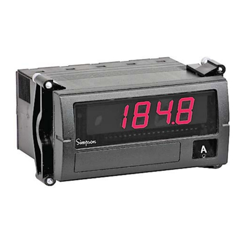
Mini-Max M245 Series Digital Panel Meter
Installation and Panel Cutout
Simpson’s Mini-Max Process Indicators provide high quality,
accuracy and reliability in a compact, 60mm deep case.
Units offer 4-1/2 digit, 0.5” (12.7mm) LCD display and are
available with a bright red, negative image backlight option.
All units feature user-selectable decimal point, auto zero and
limited scaling capabilities.
A unique mounting bracket is provided to allow for vertical or
horizontal stacking of multiple indicators. All Mini-Max units
feature a 3/64 DIN, high-impact plastic case. The standard
units have a clear viewing window, and the units with option-
al negative image, red backlighting have a red window.
DC Process
DISPLAY
Type: 7-segment LCD
Height: 0.5” (12.7mm)
Decimal point: 4-position programmable
Overrange indication: Most significant digit = “1”
Backlighting: Optional negative image, red LED
backlighting
Polarity: Auto with “-” indication, “+” implied
POWER REQUIREMENTS
AC Volt: 85-250VAC @40-440Hz
DC Volt: 9-32VDC
Power Consumption:
85-250VAC: 2.5VA min/4VA max
9-32VDC: 1.5VA min/3VA max
ACCURACY @ 25°C
±(0.02% of input + 1 count)
ENVIRONMENTAL
Operating Temperature: 0 to 55°C
Storage Temperature: -10 to 60°C
Relative Humidity: 0 to 85% non condensing
Temperature Coefficient:
All inputs ±(0.02% of input ±0.2 digit)/°C
Warmup time: Less than 20 minutes
NOISE REJECTION
NMRR: 60dB, 50/60Hz
CMRR: (w/1Kunbalanced @ 60Hz): 90dB min
ANALOG TO DIGITAL CONVERSION
Technique: Integrating
Rate: 3 samples/second-typical
MECHANICAL
Bezel: 0.95” x 2.84”
(24mm x 72mm)
MECHANICAL (cont.)
Depth: 2.36” (60mm)
Panel cutout: 0.88” x 2.68”
(22.2mm x 68mm)
Weight: 3.5oz (99.2g)
Case Material:
94-0,UL-rated, glass-filled thermoplastic
Specifications
Wiring Display
Display Scaling Span Adjustment: Mini-Max indicators have limited
range coarse and fine adjustments for display scaling.
There are no optional connections required for these
to function. The “coarse” calibration R12 will allow a
limited range of scaling values. The meter can be
scaled down to 1/2 the value of the input, but not
scaled up. Maximum scaling is maximum input or a
maximum reading of 19999, which ever is lower.
Example: A 2 volt input has a maximum reading of
1.9999 counts, so you cant double the 2 volts, but
you can make 1 volt to read 1.9999. The “fine” cal-
ibration R9 allows for an approximate range of 1% of
the “coarse” calibration. Apply the full scale input to
the meter. Adjust R12 to be within 1% of the desired
scaled value, then use R9 to obtain the final desired
result.
Offset Adjustment: To adjust the offset, apply the off-
set input signal. (e.g. 4 mA on 4-20 mA input). Use
R7 for a “coarse” adjustment of the offset. The offset
can be scaled up or down approximately 2500
counts. Adjust R7 to within 1% of the desired scaled
value, then use R6 to obtain the final desired result.
Using a screwdriver or thumbnail,
spread tab on each side of case to
unlock top half. Lift rear top half
and slide away from front of meter.
FRONT
OF METER LOCKING
TA B
TOP HALF
OF CASE
R9
R12
SCALE
ADJUST
COURSE
SCALE
ADJUST
FINE
OFSET
ADJUST
COURSE
OFSET
ADJUST
FINE
R7 R6
Decimal Point: To select a decimal point, connect the appropriate DP pin (DP1, DP2, DP3, or DP4) to DP COMMON (HOLD). Unused DP inputs
may remain unconnected (open).
Reading Hold: Connect DP4/HOLD to DP/COMMON (HOLD). If this feature is not required, the HOLD pin may remain unconnected (open).
Hold is optional on this model, and when so equipped, replaces DP4. This feature is available from our modification centers.
Input Signal: Connect the IN HI and IN LO to the signal to be monitored.
Supply Power: Connect the power to the L1 and L2 terminals. For AC powered units, L1 and L2 are not polarized.
For 9-32 VDC powered units, L1 must be positive with respect to L2.
(Input Signal) IN HI
(Input Signal) IN LO
DP3
DP2
DP1
HOLD
L1 (POS) (Power)
L2 (NEG) (Power)
EX (NEG)
EX (POS)
DP COMMON
(HOLD)
These instruments are designed for maximum safety to the operator when mounted in a panel according to
instructions. They are not to be used unmounted or for exploratory measurements in unknown circuits.
Range Resolution Voltage
Max Input
Drop (unfused)
4-20mA 0.1% 200mV 100mA
Range Resolution Input Maximum
Impedance Input
1-5VDC 0.1% 10M 750V
0-10VDC 0.1% 10M750V
0-100VDC 0.1% 10M750V
INPUTS: DC Process
DP4/
Note: Any physical damage to the meter
during calibration will void the warranty
Stacking Features
The mounting brackets, included with every Mini-Max, can be connect-
ed together. Multiple units can be mounted in a single opening, allow-
ing perfect alignment.
To punch one hole for multiple units, be sure to adjust the standard
panel cutout dimensions as shown here; otherwise the meters will not
fit properly in the hole.
Mounting multiple units is quick and easy. Install the first meter (bottom
unit first if stacking vertically). Position the next mounting bracket snug-
ly against the first one, and slide the second meter into place. Repeat
for remaining units.
2.68" (68 mm)
.071" (1.8 mm)
.88" (22.2 mm)
Standard cutout
Add to standard
when stacking
.88" (22.2 mm)
2.68" (68mm)
Standard cutout
.16" (4.0mm)
Add to standard when stacking
Horizontal
Vertical
Vertical
Horizontal
Excitation Output
Excitation output is available in the Mini-Max for
powering external transmitters or transducers.
Excitation is available from the EX POS and EX NEG
terminals. This source is isolated from the measure-
ment input as well as the input power circuits. The
voltages available are 12VDC or 24VDC, with a
maximum load current of 25 milliamps. This feature
eliminates the need to mount an external DC power
source for transducers or sensors used in your
application.
Do not exceed an excitation
load current of 25mA!
EX NEG
EX POS
Backlight Option and Decimal Point Selection
Negative image, bright red backlighting is available
in the Mini-Max. This illumination allows the unit to
be read in low light areas. Backlighting power is
supplied by the Mini-Max, so no additional external
power is required.
Decimal point selection is accomplished by con-
necting the appropriate DP terminal to the DP
Common terminal.
DP COMMON
(HOLD)
321 G
DP 4
DP 2
DP 3
4*
*NOTE: If the Display
Hold option is ordered,
it replaces DP4 on the
Terminal Connector.
DP 1
DP4
DP3
DP1
DP2
Application Example
Ordering Information Safety Symbols
The WARNING sign
denotes a hazard. It calls
attention to a procedure,
practice, or the like,
which, if not correctly
performed or adhered to,
could result in personal
injury.
The CAUTION sign
denotes a hazard. It calls
attention to an operating
procedure, practice, or
the like, which, if not cor-
rectly adhered to, could
result in damage to or
destruction of part or all
of the instrument.
Remote temperature (0-300°) monitoring of a liq-
uid storage tank is required.
A 4-20mA transmitter is placed in a thermal pro-
tection head. The thermocouple located in the
thermal head gives a mV signal to the transmitter,
which sends out to the Mini-Max a 4-20mA sig-
nal. This allows the Mini-Max to be in a remote
location, such as a control room. The Mini-Max
inputs and display must be scaled prior to con-
necting the 4-20mA signal.
After scaling the unit, the 4-20mA signal is con-
nected to the IN HI and IN LO terminals, and the
Mini-Max will display the temperature of the tank.
Non Backlight
Negative Image Red
Basic Unit Display DPM Power Supply Range Excitation Output
M245
0
2
0
1
0
1
2
71
72
73
74
4-1/2 Digit Indicator
85-250VAC
9-32VDC
4-20mA
1-5VDC
0-10VDC
0-100VDC
None
12VDC
24VDC
EXCITATION POWER
LIQUID STORAGE TANK
4-20 mA OUT
The Mini Max Process Indicator can be configured by making an entry for each box
NOTE: Display hold feature is configured at the factory only. Must specify at time of order.
SIMPSON ELECTRIC COMPANY 853 Dundee Avenue, Elgin IL 60120-3090 • (847) 697-2260 • FAX (847) 697-2272
www.simpsonelectric.com Printed in U.S.A. Part No. 6-116074, Edition 13, 03/05
NOTE: Special scaling is available from the factory at the time of odering.

This manual suits for next models

1

Other Simpson Measuring Instrument manuals

Simpson Gima User manual

Simpson

Simpson Gima User manual

Simpson 215 User manual

Simpson

Simpson 215 User manual

Simpson SPEEDMULLER User manual

Simpson

Simpson SPEEDMULLER User manual

Simpson 880 WATTMETER User manual

Simpson

Simpson 880 WATTMETER User manual

Simpson Falcon F35 Series User manual

Simpson

Simpson Falcon F35 Series User manual

Simpson 260-6XLM User manual

Simpson

Simpson 260-6XLM User manual

Simpson 2865 User manual

Simpson

Simpson 2865 User manual

Simpson S664 User manual

Simpson

Simpson S664 User manual

Simpson 260-8P User manual

Simpson

Simpson 260-8P User manual

Simpson S663 User manual

Simpson

Simpson S663 User manual

Simpson 260 series 5M User manual

Simpson

Simpson 260 series 5M User manual

Simpson 260-8PRT User manual

Simpson

Simpson 260-8PRT User manual

Simpson 897 User manual

Simpson

Simpson 897 User manual

Simpson 260 Series 8 User manual

Simpson

Simpson 260 Series 8 User manual

Simpson 897 User manual

Simpson

Simpson 897 User manual

Simpson 260-8XI User manual

Simpson

Simpson 260-8XI User manual

Simpson 228 User manual

Simpson

Simpson 228 User manual

Simpson 390-2 User manual

Simpson

Simpson 390-2 User manual

Simpson 260-8XPI User manual

Simpson

Simpson 260-8XPI User manual

Simpson Falcon F45 Series User manual

Simpson

Simpson Falcon F45 Series User manual

Simpson 260-6XLPM User manual

Simpson

Simpson 260-6XLPM User manual

Simpson ES 1000/400A User manual

Simpson

Simpson ES 1000/400A User manual

Simpson 444 User manual

Simpson

Simpson 444 User manual

Simpson 260 series 5M User manual

Simpson

Simpson 260 series 5M User manual

Popular Measuring Instrument manuals by other brands

PCB Piezotronics 607A11/001AC operating guide

PCB Piezotronics

PCB Piezotronics 607A11/001AC operating guide

Omnik Omniksol-WIFIKIT user manual

Omnik

Omnik Omniksol-WIFIKIT user manual

Rebel MIE-RB-266 user manual

Rebel

Rebel MIE-RB-266 user manual

Metrohm 780 manual

Metrohm

Metrohm 780 manual

Image Engineering LED-Panel V4 user manual

Image Engineering

Image Engineering LED-Panel V4 user manual

Trotec MultiMeasure BASIC operating manual

Trotec

Trotec MultiMeasure BASIC operating manual

DeWalt DW03050 user manual

DeWalt

DeWalt DW03050 user manual

R&S ZND Getting started

R&S

R&S ZND Getting started

OLBA HH-70 Instructions for use

OLBA

OLBA HH-70 Instructions for use

SIGLENT CP6000 Series instructions

SIGLENT

SIGLENT CP6000 Series instructions

Newport CONEX-LDS Command Interface Manual

Newport

Newport CONEX-LDS Command Interface Manual

Sensus SonixIQ 250CFH quick guide

Sensus

Sensus SonixIQ 250CFH quick guide

geo-FENNEL S-Digit multi user manual

geo-FENNEL

geo-FENNEL S-Digit multi user manual

Tektronix TLA5202 Service manual

Tektronix

Tektronix TLA5202 Service manual

Marvin GX2472 Driver manual

Marvin

Marvin GX2472 Driver manual

MEYTEC GT-200RX manual

MEYTEC

MEYTEC GT-200RX manual

Johnson Level & Tool 40-6601 instruction manual

Johnson Level & Tool

Johnson Level & Tool 40-6601 instruction manual

Megasat Digital 1 HD user manual

Megasat

Megasat Digital 1 HD user manual

manuals.online logo
manuals.online logoBrands
  • About & Mission
  • Contact us
  • Privacy Policy
  • Terms and Conditions

Copyright 2025 Manuals.Online. All Rights Reserved.