Gason Pasture Planter User manual
A member of
COPYRIGHT
Neither this manual or part thereof may be reproduced or published without the prior permission of AF Gason Pty Ltd
PASTURE PLANTER
ASSEMBLY, OPERATORS & PARTS MANUAL
GPN 215645 REVISION A 06/14
AIR SEEDER
PASTURE PLANTER

Page Intentionally Blank

CONTENTS
06/14
Warranty Form
Introduction...............................................................
1
Safety.......................................................................
2
Bolt Specifications....................................................
3
Ordering Parts..........................................................
4
Spare Parts Record..................................................
5
Distribution Kits Options ...........................................
7
Distribution Kits & Fitment Information......................
Broadcast Dist. Kit...........................................
8
Individual Placement System...........................
10
Combiner ‘Y’ Kit...............................................
11
Operating the Pasture Planter ..................................
12
Adjustments..............................................................
13
Fitment of Reducer Plate........................
13
Removal of Meterwheel Cover Plate.......
14
Changing Meterwheel.............................
14
Ground Drive Calibration..........................................
15
Calibration Handle Turns........................
18
Planting Details Reference .....................
19
VRT Hydraulic Drive Calibration ...............................
21
Planting Details Reference .....................
24
Spare Parts ..............................................................
26

06/14
Page Intentionally Blank
INTRODUCTION
Page 1
06/14
The Gason Pasture Planter has been
designed to operate in conjunction with the
range of Gason Air Seeders. The Pasture
Planter, sometimes referred to as a small seeds
box, is generally mounted direct to the Seeders
bin. It utilizes the seeders drive system to
operate the metering system and the blower to
convey the product.
The Gason Pasture Planter metering
system is a positive and accurate method of
placing small seeds into the air stream. The
system is capable of sowing a wide variety of
small seeds and other products with minimal
adjustment.
The Gason Pasture Planter bin capacity
has been designed to match the capacity of your
Gason Seeder.
380 litres for seeders with a main bin
capacity of 5,000L or less.
600 litres for seeders with a main bin
capacity of 6,000L or greater.
It will hold approximately 270kg / 420kg of canola
depending on the products density.
There are a number of distribution kits that
can be fitted to your implement and connected to
the Pasture Planter.
a) Broadcast Distribution Kit
b) Individual Placement System
c) Combiner ‘Y’ System
The distribution kits are more fully
explained in the Distribution System Option’s
sections of this manual.
Please read the appropriate sections of this
manual before assembling and operating your
machine. Field experience has shown that a
good understanding of the features and correct
method of operation greatly reduces problems in
the field.
References to the left and right hand sides
of the Air Seeder are from the rear of the
machine looking forward.
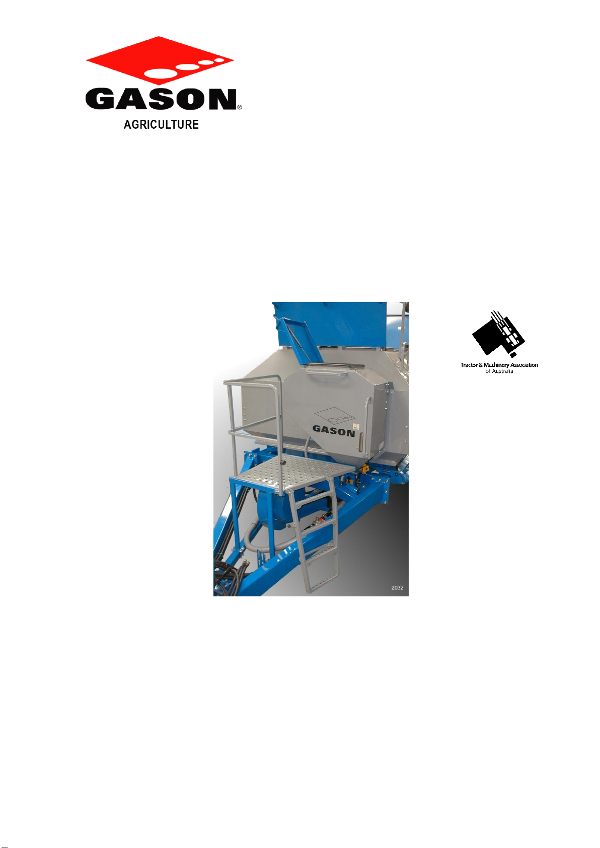
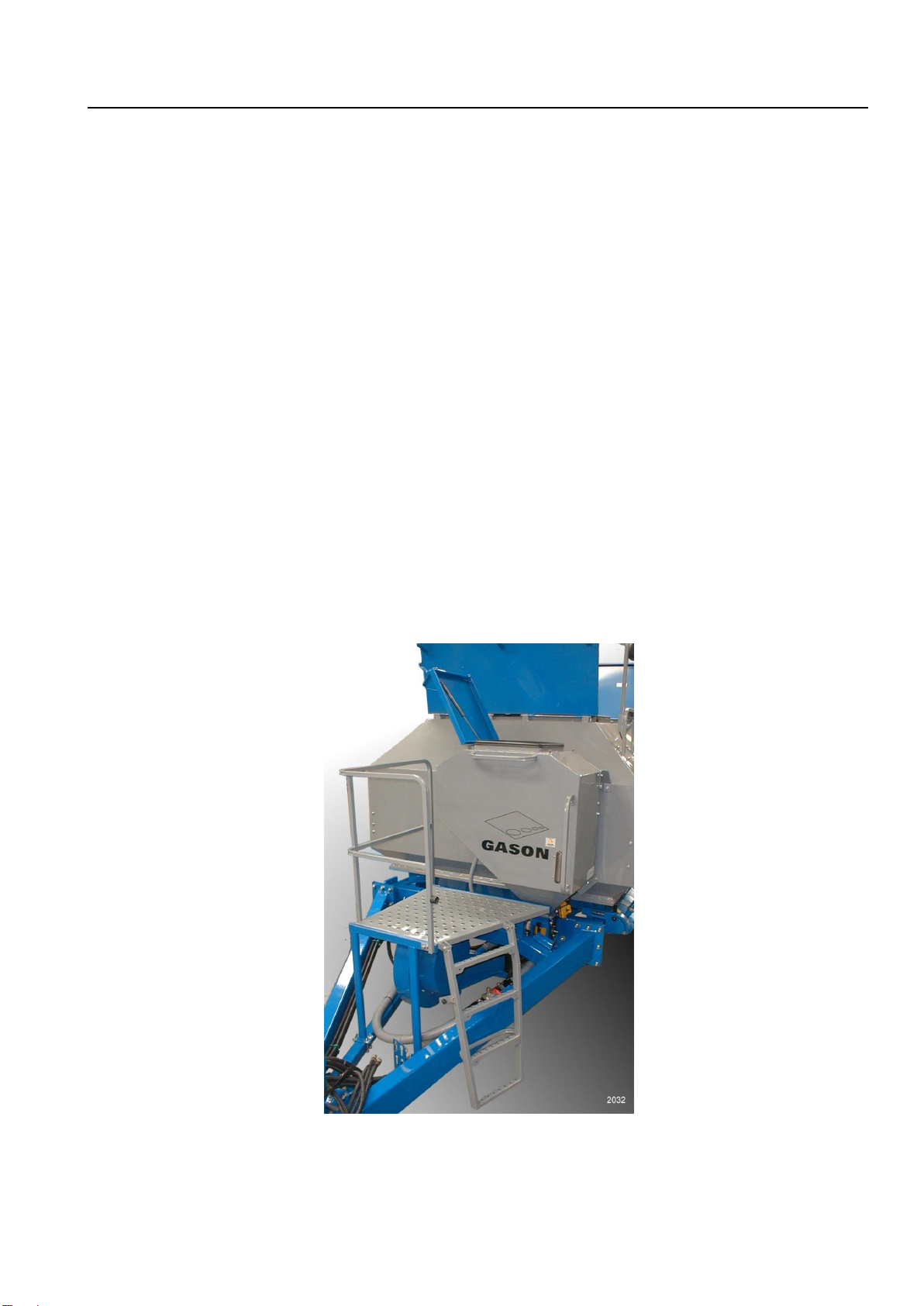
Fig. 1 Pasture Planter mounted on a Front Tow Air Seeder
While every effort has been made to ensure the accuracy of the information in this manual, A.F.Gason Pty. Ltd.
Reserves the right to delete, change or add information without notice.

SAFETY Page 2
10/09
The Air Seeder has been designed with
safety in mind. However, the equipment is
only as safe as the person operating it.
Do not operate the Air Seeder until you
have read and understood this manual. If you
feel you need help or advice on the operation of
the Seeder, contact your local authorized Gason
Dealer.
To ensure trouble free and safe operation
of your seeder, it is important to carry out a daily
safety check to reduce the possibility of a costly
breakdown.
Items to Check Daily During Operation
1.Check all wheel nuts are tight during the
first couple of days of seeding or after
transportation.
2.Check all tyre pressures and tyre
conditions in general. NOTE: a badly
worn rear drive tyre will affect the
metering accuracy.
3.Ensure the safety guard on the blower unit
is fitted.
4.Check all hydraulic breakaway
connections are locked into position.
5.Check all hydraulic hoses and fittings for
leaks.
6.Check all chains and sprockets for wear or
movement on the shaft.
7.Check metershafts turn freely before
operating each day or after transporting
when loaded.
8.Check draw bar pins for wear.
9.Ensure bin lids are closed and that there
are no air leakswhen blower is operating.
10. Check distribution hoses for damage or
kinks, especially after operating the wing
fold system on the implement.
General Safety Conditions
DO NOT ride on the machine when
operating.
DO NOT touch or attempt to adjust any
moving parts.
DO NOT adjust hydraulic fittings while under
pressure.
DO NOT remove any safety guards while the
seeder is operating.
DO carry out the daily safety checks and operate
the seeder in a safety conscious manner.
Hydraulics
Before working on the hydraulic system
always check that the blower is not operating,
and that there is no pressure in the hydraulic
system.
Never attempt to disconnect a breakaway
coupling if the blower is operating. Turn the
tractor off if working on the metering system of
a VRT equipped seeder.
Leaving the Air Seeder Unattended
Always close the bin lids and ensure that
no material is left in the bins after seeding.
Chock the Air Seeder wheels to prevent it
from rolling.
When Working on the Air Seeder
Place suitable stands under the trailer if
removing a wheel or carrying out major work.
Never enter the bin compartment unless
another person is present. Always take proper
safeguards if entering a bin or working on
components that have been exposed to treated
seed.

BOLT SPECIFICATIONS
Page 3
10/09
CAUTION: Loose bolts can cause elongation of holes and part failures resulting in dangerous operating
conditions and equipment breakdown. Check all bolts and nuts periodically during equipment
operation and keep them tightened to the specified torque. If hardware replacement becomes
necessary, replace with equivalent metric grade number.
NOTE: The following torque figures are those recommended for zinc plated, lightly oiled bolts.
Recommended assembly torques may be obtained by multiplying the torque figures in the
table below by:
0.78 –for degreased zinc plated bolts
1.10 –for black oxide finished bolts
0.81 –for M20x2.5P Tine Toolbar Hardware
It is necessary that all bolts be tightened to the correct recommended assembly torque.
lbf.ft Nm lbf.ft Nm lbf.ft Nm
7/16 UNF 43 59 60 82 - -
7/16 UNC 39 53 54 74 - -
1/2 UNF 67 91 94 128 - -
1/2 UNC 59 81 83 113 - -
5/8 UNF 135 184 186 253 - -
5/8 UNC 117 159 165 224 - -
3/4 UNF 235 319 325 441 - -
3/4 UNC 210 285 290 394 - -
7/8 UNF 370 502 520 706 - -
7/8 UNC 335 455 470 638 - -
1UNF 550 746 775 1052 - -
1UNC 505 685 710 963 - -
M10 1.5 29 40 41 56 - -
M12 1.75 51 70 73 100 - -
M16 - - - - - 170 231
M16 2.0 126 171 180 245 - -
M18 - - - - - 243 330
M20 - - - - - 265 360
M20 2.5 247 335 351 477 - -
M22 - - - - - 340 462
M24 - - - - - 370 502
M24 3.0 425 577 608 825 - -
Recommended Assembly Torque
8.8
10.9
Wheel Stud
Metric Grade Number
S.A.E Grade Number
5
8
Size
Thread
Pitch
Wheel Stud
Head Markings
(Manufacturers marks
mayvary)
Head Markings
(Manufacturers marks
mayvary)
ORDERING PARTS
Page 4
10/09
When Ordering Parts:
The following information must be supplied
to facilitate fast and accurate processing of a
replacement parts order:-
•Gason part number and description (as
given in this manual)
•Quantity
•Machine model and serial number
•Method of despatch.
•Your Dealers name and address
For your convenience record the following
information below:
Name: ______________________________
Address: _____________________________
Telephone Number: ____________________
Machine Model No:_____________________
Date Machine Purchased:________________
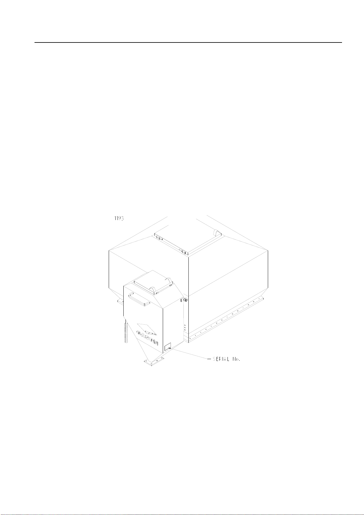
Serial No.:____________________________
Fig.3
Subject to any applicable Federal, State or Territory laws or ordinances, which may apply from time to time, A. F.
Gason Pty Ltd reserves the right to make changes in design and specifications without notice or obligation and to
change or discontinue models at any time without incurring any liability to any Purchaser thereof.
Left and right hand: All references in this manual are determined by facing the direction of travel.
For warranty provisions please consult your Installation and Warranty Registration document.

SPARE PARTS RECORD
Page 5
10/09
PART No.
DESCRIPTION
QTY.
COST
DATE

Page Intentionally Blank
DISTRIBUTION KIT OPTIONS Page 7
06/14
Distribution Kits Options
As mentioned in the introduction, there are
a number of distribution kits that can be fitted to
your implement and connected to the Pasture
Planter.
a) Broadcast Distribution Kit
b) Individual Placement System
c) Combiner ‘Y’ System
1. Broadcast Distribution Kit
A Broadcast Distribution Kit can be fitted to most
Gason implements. Kits are supplied to suit
different implement widths. Each kit is supplied
with sufficient towers, heads, hoses and scatter
plates to allow for 450mm-600mm wide spacing
between toolbar mounted outlets. Mounted on
the rear row of the implement, light rates of seed
can be evenly scattered across the ground.
Fig. 4 Broadcast scatter plates mounted on bar.
2. Individual Placement System
The Individual placement system can allow for
low rates of small seeds to be placed throughout
the implement similar to the main distribution
system.
Gason’s do not manufacture a specific
sowing boot for the smaller final 12.7mm ID hose
but do have an adaptor that can be fitted to a
standard 32mm ID Gason sowing boots.
Alternatively, owners/dealers may wish to make
up their own sowing outlet device specific to their
requirements. This individual placement system
will service a maximum of 55 outlets.
Fig. 5 Secondary head used on the Broadcast
and Individual Placement Systems.
3. Combiner ‘Y’ System
The Combiner ‘Y’ System allows the operator to
combine product from the pasture planter into a
number or all of the main primary distribution
hoses. This can be particularly useful for planting
canola or other small seeds at low rates from the
pasture planter and combining them with
product, such as fertiliser, from the main seeder
bins.
Product can then be directed down a tine
or disc opener as required. Combiner systems
are normally ordered in kits to suit the number of
main primary hoses you wish to feed into.
Common kits are 2, 3, 4 and 6 outlet systems.
Individual kits are also available if required.
Fig. 6 A Combiner ‘Y’ tube fitted to a primary
hose. Note the 25mm hose from the pasture
planter’s distribution system attached.
DISTRIBUTION KITS & FITMENT INFORMATION Page 8
06/14
Broadcast Distribution Kit Fitment
Instructions (refer fig. 7 and 8.)
1. Attach the primary manifold support and
bracket (Items 12 & 13) using the M10 U -
Bolt to the last or secondlast row near to the
centre of the implement frame. Place the
primary manifold (Item 29) on top of the
manifold support. Connect a length of grey
50mm hose (Item 35) between the camlock
fitting (Item 25) and the manifold support.
Use bracket (Item 27) to secure camlock
fitting and attach the hose tothe frame using
the plastic ties (Item 34).
2. Attach thefive port secondary manifolds and
support brackets (Item 17, 22 & 37) to the
last row of the implement at approximately
2.5 metre spacings.
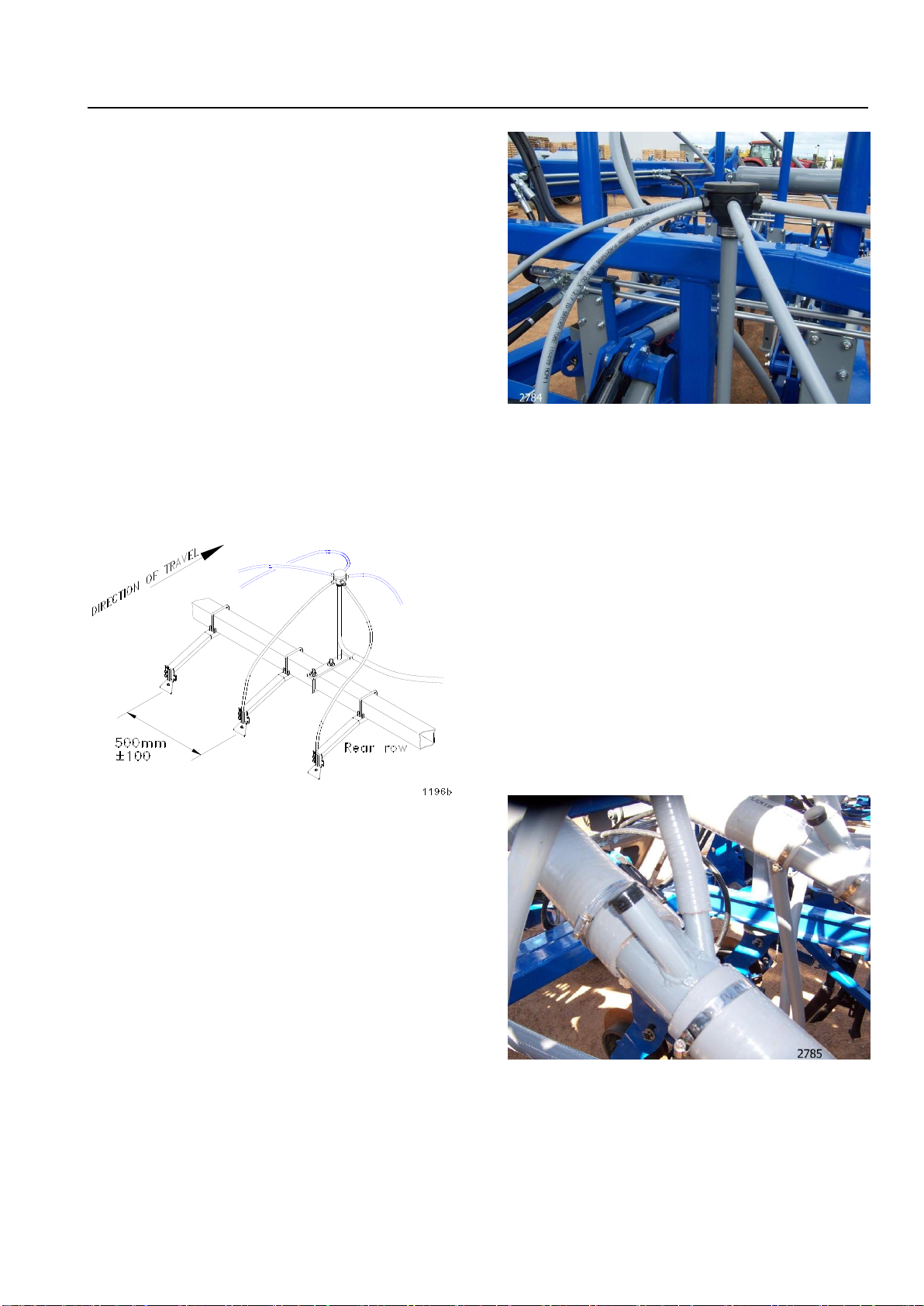
3. Attach the spreader assemblies (Item 1)
using the U-Bolts supplied to the last row of
the implement at approximately 500mm
spacings. Do not tighten as the 13mm
hose will be held between these assemblies
and the frame.
4. It may be necessary to use a spreader
extension (Item 7) to position the spreader
assemblies further rearward to clear
machine obstructions. Typical problem
areas are where cylinder mount brackets
protrude out the back of a machine or if a
tine tower is obstructing clear flow of the
seed.
5. Connect the outlets of the primary manifold
(Item 29) to the secondary manifold support
pipes (Item 22) using the 25mm grey hose
(Item 10). When cutting the hose to length,
ensure the shortest hose is not less than
half the length of the longest hose
(Example: 4 outlet primary head –the 2
long hoses are 8m therefore any
remaining hoses are not to be less than
4m). Allow slack, where necessary for wing
folding and secure these hoses to the frame
using plastic ties. Avoid dipping of hoses to
prevent material build-up and blockages.
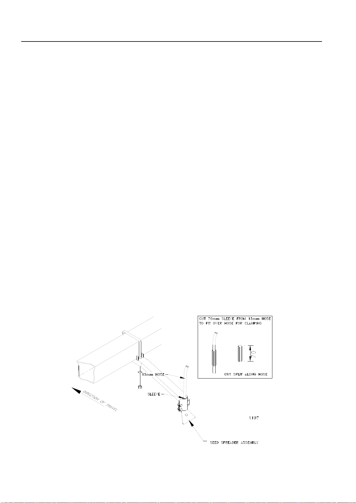
6. Connect the outlets of the five port
secondary manifold assemblies to the
spreader assemblies using the 13mm hose
(Item 28). When cutting the hose to length,
ensure the shortest hose is not less than
half the length of the longest hose. These
hoses should RUN DIRECTLY TO the
assemblies (not down and along the frame)
and are clamped between the spreader
assemblies and the frame.
To ensure the hose is firmly clamped a
sleeve will need to be cut and placed over
the hose at the clamped position (see Fig.
7). Allow 25mm between the hose outlets
and the spreader plates and when secure
check the alignment of the spreader plates
(see Fig. 7).
Fig. 7
DISTRIBUTION KITS & FITMENT INFORMATION Page 9
06/14
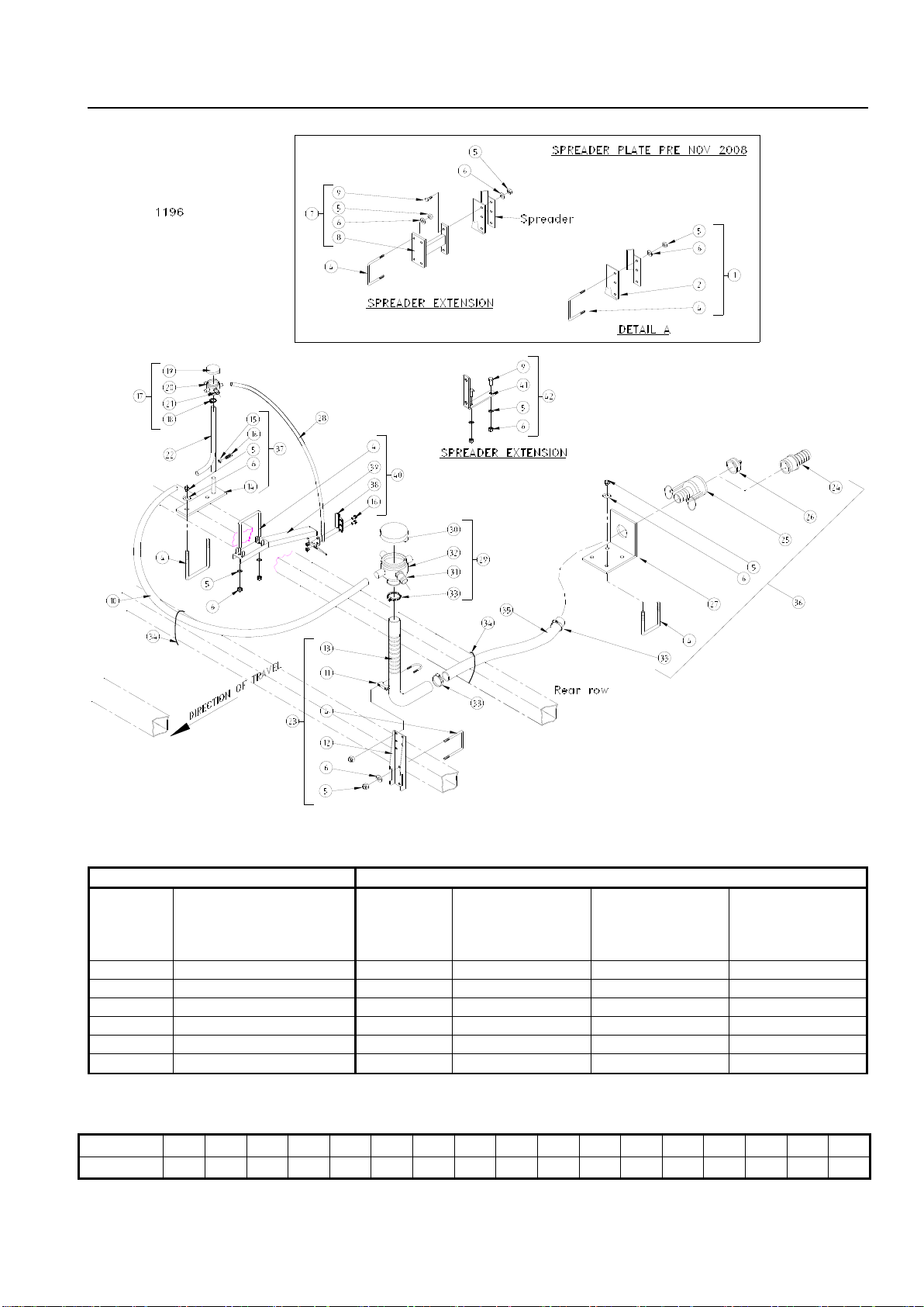
Fig. 8 Pasture Planter Broadcast Distribution System
Note: Refer to spare parts section for all part numbers
DISTRIBUTION SYSTEM
COMPONENTS SUPPLIED
KIT
GPN:
IMPLEMENT WIDTH
PRIMARY
MANIFOLD
(ITEM 29)
SECONDARY
MANIFOLD
(ITEM 17)
SEED
SPREADER
ASSEMBLY
(ITEM 40)
SPREADER
EXTENSION
(ITEM 42)
215634
4 to 5.5 metres
2 outlet
2 qty
10 qty
2 qty
215636
6 to 8.5 metres
3 outlet
3 qty
15 qty
4 qty
215638
9 to11.5 metres
4 outlet
4 qty
20 qty
4 qty
215640
12 to 14.5 metres
5 outlet
5 qty
25 qty
4 qty
215642
15 to 17.5 metres
6 outlet
6 qty
30 qty
6 qty
215644
18 to 20.5 metres
7 outlet
7 qty
35 qty
8 qty
Metric to Imperial Conversion Scales : 1m = 3.28ft
m
4
5
6
7
8
9
10
11
12
13
14
15
16
17
18
19
20
ft
13
16
20
23
26
30
33
36
39
43
46
49
52
56
59
62
66

DISTRIBUTION KITS & FITMENT INFORMATION Page 10
06/14
Individual Placement System Fitment
Instructions (refer fig. 9.)
1. Attach the primary manifold support and
bracket (Item 9) using the M10 U-Bolts and
fasteners to a central location on the
implement. This central location will reduce
the length of the 25mm secondary hose
that needs to be routed across the
machine.
2. Fit the small Secondary towers & heads
(item 2) centrally amongst the tines to be
serviced.
3. Use the 12.7mm ID hose to distribute the
small seeds to the appropriate sowing boot
supplied by the owner or to a dedicated
Gason sowing boot with the aid of an
adaptor (item 7).
Fig. 9 Pasture Planter Individual Placement System
DISTRIBUTION KITS & FITMENT INFORMATION Page 11
08/14
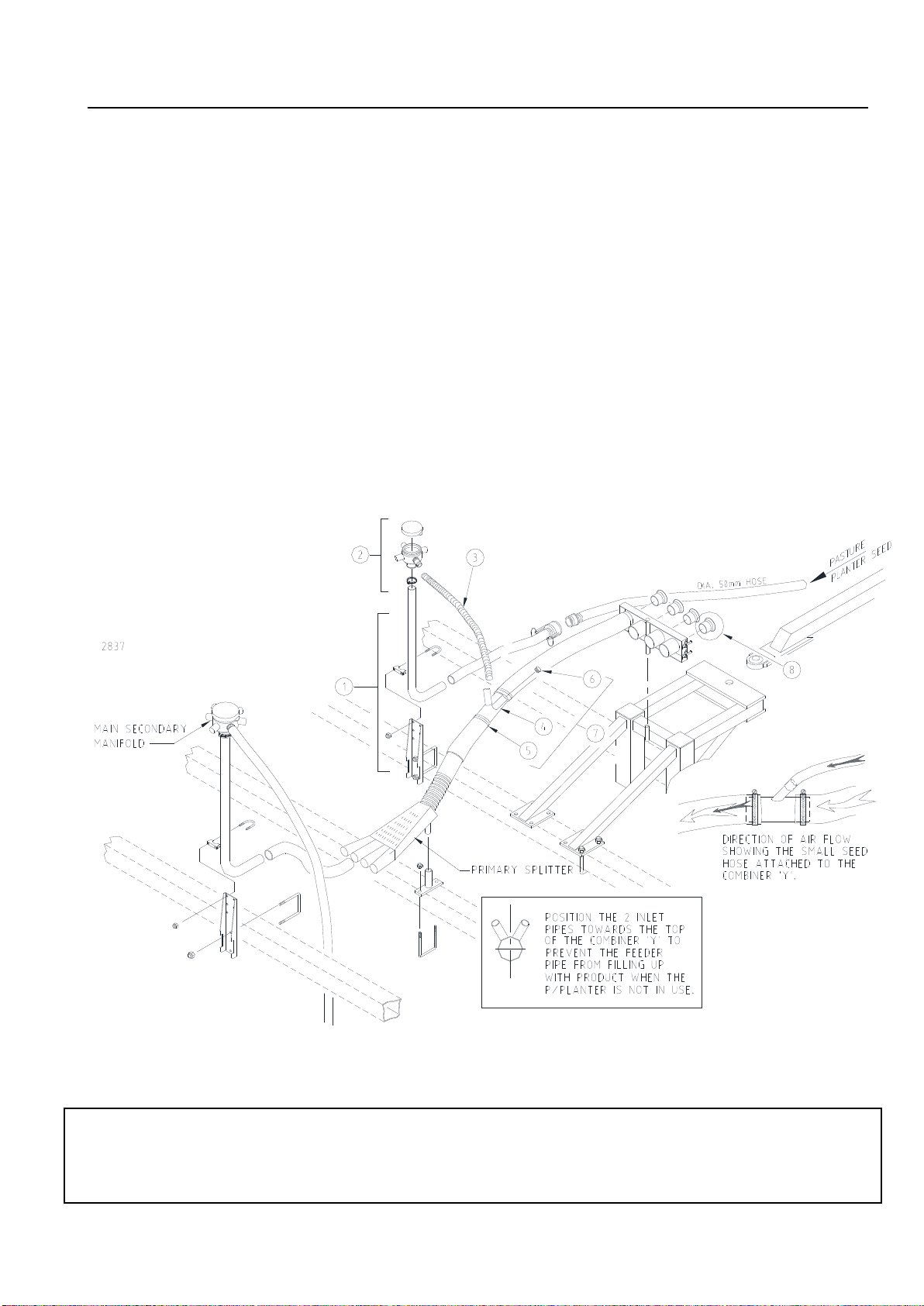
Combiner ‘Y’ Kit Fitment Instructions
(refer fig.10.)
Combiner ‘Y’s can be fitted to multiple
primary hoses to allow the incorporation of
product from the Pasture Planter to the main
distribution system. The position and direction of
fitment of the Combiner ‘Y’s is important and if
not done correctly will cause distribution issues.
If operators are wishing to combine
material from the pasture planter down all of the
tines on a single shoot system, they would select
a quantity of combiners the same as the number
of primary hoses fitted. If the objective was to
plant on the rear row only on a machine that had
a deep banding system, then only half the
number of combiners will be required.
1. Attach the full height primary manifold
support kit (item 1) near the entry side of the
cluster of primary seeder splitters. By doing
this, it will be easier to maintain short and
continuously falling 25mm secondary hoses
from the primary manifold to the inlet on the
Combiner ‘Y’s.
2. Ensure any open 25mm inlet pipes on the
Combiner ‘Y’s are capped with the supplied
black plastic cap (item 6). Two are supplied
with each kit.
3. Both inlet pipes must be set in the correct
direction and so that they are facing upwards
as per the sketches in Fig.10 below.
Fig. 10 Combiner ‘Y’ System showing one possible configuration.
Note regarding the use of the equalisation funnels (item 8) supplied with the combiner ‘Y’ Kit.
Equalisation funnels have been supplied for use in distribution system with a high back pressure in the
main Secondary system. They are rarely used but can be helpful in restricted systems with either a small
number of tertiary outlets or restricted sowing boots. If used, they must be fitted to all primary lines.
OPERATING THE PASTURE PLANTER Page 12
10/09
General Information
The pasture planter has been designed to
integrate with the complete range of Gason Air
Seeders. General operation of the pasture
planter is similar to the main system.
It will be necessary to calibrate the pasture
planter metering system to obtain the desired
application rate for the particular material being
sown. Refer to either the Ground Drive or VRT
Hydraulic Drive sections in this manual for the
appropriate calibration information.
For a more detailed description of Air
Seeders operation refer to the Air Seeder
Operator’s Manual.
Setting Pasture Planter Air flow
The Pasture Planters air supply is taken
from a secondary outlet on the plenum chamber
and is controlled by a shut off valve. For general
use the valve will be fully open when operating
the pasture planter. Fan speed setting is based
upon application rate in the seeders main
system.
Fan speed may need to be varied
depending on type and size of distribution
system and application rate through main
system and pasture planter. The shut off valve
can be used to restrict airflow to the Pasture
Planter if required.
Contact your Gason dealer for specific
information about Pasture Planters air flow.
Filling the Bins
Before filling, check that the clean out
hatch on the meterbox has been fixed into
position, and that there are no adjustments
needed to the Pasture Planter meterbox.
The grate that is fitted to the top of the bin
should always be left in place when filling. This
will help in preventing large clumps of material
and foreign objects from entering the bin and
possibly damaging or blocking the meter system.
To Empty the Bin
Place a suitable container underneath the
pasture planter and open meterbox clean out
hatch. To ensure all of the bin’s contents has
been removed it is recommended that you open
the bottom door of the Pasture Planter and rotate
the metershaft one full revolution.
Use a broom from the top of the bin if any
material remains in the bin.
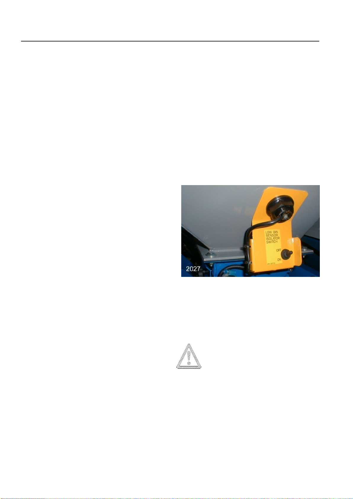
Low Bin Sensor - Ground Drive Only
The “Low Bin Sensor Isolation Switch”
enables the sensors in the main bins to operate
independently of the pasture planter. When
operating the Pasture Planter the bin sensor
needs to be turned ON.
Fig.11 Low Bin Sensor Isolation Switch
Disengaging Pasture Planter –Ground Drive
Only
When the pasture planter is not in use, set the
variator to zero. This effectively disengages the
metershaft.
The Pasture Planter Metershaft will
still gradually creep when variator is
set to zero.

PASTURE PLANTER METERBOX - ADJUSTMENTS Page 13
10/09
Fitment of Reducer Plate
To achieve very low rates with small seeds
a reducer plate is fitted to the Pasture Planter
meterbox. This reduces the meterwheels output
to approximately 1/3. The following steps are for
fitment ofthe reducer plate, removalis a reversal
of this procedure.
Step 1. Remove window assembly.
Fig.12 Removal of window assembly
Step 2. Fit reducing plate onto bolt inside the
meterbox.
Fig.13 Fit reducing plate.
Step 3. Fit wing nut and tighten and then refit
window assembly.
Fig.14 Wing nut securing reducer plate.
Caution: Only use with very small seeds such as
Canola, Medics (clover seed) or Sorghum.
Always re-calibrate Pasture Planter after
fitting or removing the reducer plate.
Pasture Planter Meterbox - Adjustments Page 14
10/09
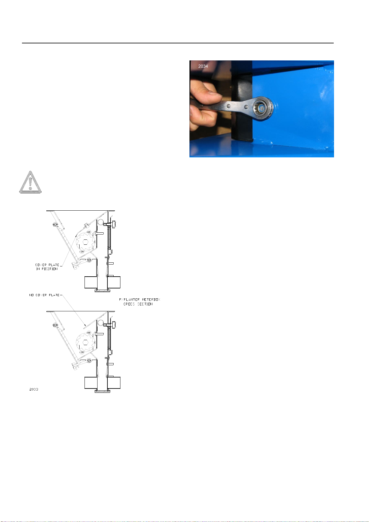
Removal of Meterwheel Cover Plate
It may be necessary to remove the
meterwheel cover plate from inside of the
meterbox for lightweight and large seed if high
rates are required.
To remove the cover plate you will need to
have the bin empty. Gaining access through the
clean out hatch, remove the M8 nyloc nut
retaining the cover plate with a 13mm ratchet
ring spanner (Refer Fig.16). Fitting cover plate is
the reversal of this procedure.
Always re-calibrate Pasture Planter after
removal or fitting of cover plate.
Fig. 15 Cover plate fitted and removed.
Fig.16 Access to remove cover plate through
clean out hatch.
Changing Meterwheel
It is possible to replace the standard
meterwheel with a more aggressive and deeper
meterwheel if metering large and light seeds at
high rates.
Refer parts section for more detail.
GROUND DRIVE - CALIBRATION Page 15
10/09
Introduction
The calibration procedure involves the
rotation of the metering system by hand to
simulate the coverage of a certain area. A
material sample needs to be collected and
weighed to calculate the application rate. This is
done by taking a sample equal to 1/20th of a
hectare.
It will be necessary to disengage the drive
system for the main air seeder when calibrating
the pasture planter.
For more detail on calibration refer: Air Seeder
Operator’s Manual, Ground Drive –Calibration.
When calibrating, ensure that there is
enough material in the Pasture Planter Bin. In
most cases 1/2 a bag will be sufficient.
It must be remembered that this style of
seeder is dependent upon a correct wheel
diameter for its operating accuracy. If this
diameter is altered, (e.g. incorrect tyre fitted,
wrong tyre pressure or extreme ground
conditions), inaccurate metering may occur. If
extremely accurate metering is desired refer to
Air Seeder Operator’s Manual, Ground Drive –
Calibration - Method C for checking the wheel
circumference.
Meterbox Adjustments
It may be necessary to make adjustments
to the pasture planter meterbox when metering
low or high rates of seed. The meterbox has
been supplied with a reducer plate (yellow) that
is fitted to the front face of the meterwheel
opening. This plate is suitable for light to average
application rates of small seeds. This plate
should be removed when metering high rates of
seed or large/light seeds (eg. rye grass).
As a guide, the variator setting should be
between 1 and 7 after calibration. If the setting is
too low you may need to fit the reducing plate if
not already in place. If the setting is too high,
above 7, remove the reducing plate if fitted and
recalibrate.
When using product that has poor flow
characteristics or larger seeds it may be
necessary to remove the meterwheel cover
plate. Refer to the adjustments section of this
manual for further information.
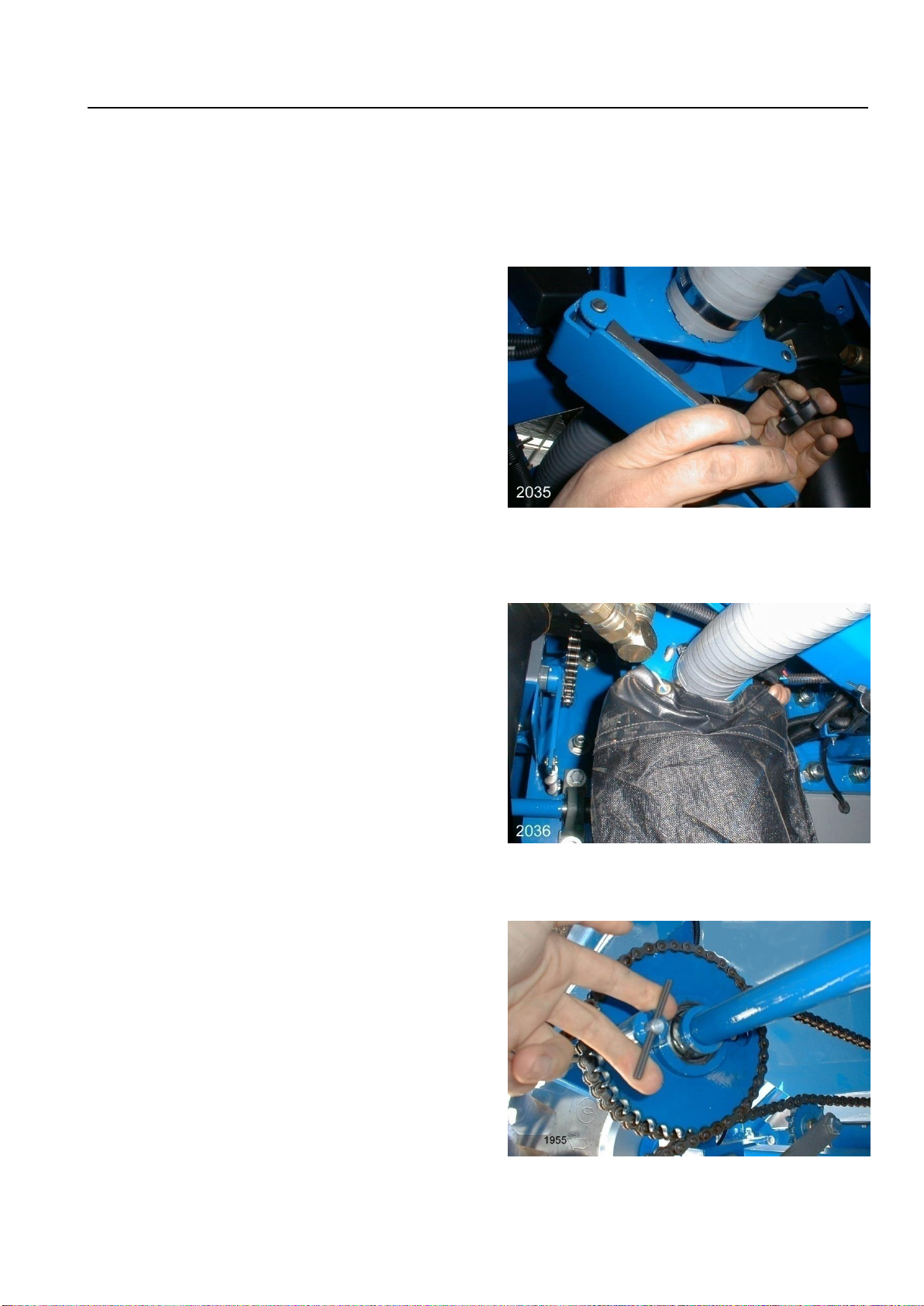
Calibration Procedure
Step 1. Open the bottom door of the Pasture
Planter.
Fig.17 Bottom door on pasture planter.
Step 2. Fit calibration collection bag to the
p/planter meterbox using the draw
string.
Fig.18 Fitting the calibration collection bag.
Step 3. Disengage drive pin from the seeders
main bins.
Fig.19 Disengaging Sprocket.
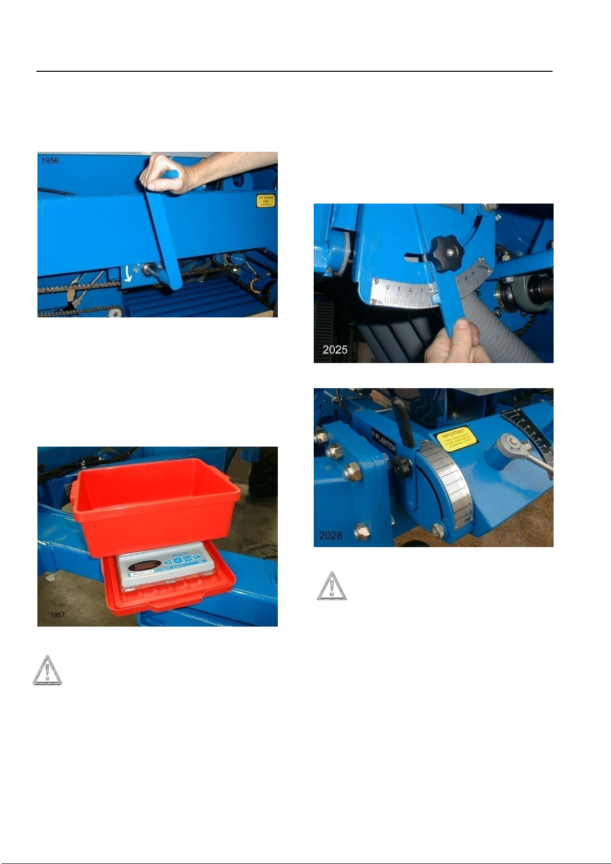
Ground Drive - Calibration Page 16
10/09
Step 4.Rotate calibration handle for the correct
number of turns to simulate 1/20th of a
hectare (see table page 14). Rotate
handle anti-clockwise.
Fig.20 Calibration handle rotates anti-clockwise,
as shown by the arrow.
Step 5.Weigh sample taken on scales supplied.
When using scales use the scale box as
the container. Place box on top of scales
before switching on. Check that the
scales are set at zero before weighing
sample.
Fig.21 Scales.
NOTE: It is the responsibility of the
operator to check the accuracy of the
scales on a regular basis.
Step 6.If the result is too low you will need to
increase the setting on the variator. If too
much material was collected the reverse
applies. After making the adjustment you
will need to retest the system following
steps 4 and 5.
NOTE: It is recommended that when adjusting
the variator setting the operator goes past the
desired setting (higher rate) a short distance and
then rotates the handle back to the required
setting. This method of adjustment will ensure
that there is no slack in the cable if a cable is
fitted.
Fig. 22 1830/50 P/Planter Variator Adjustment
Fig.23 1880/2120 P/Planter Variator Adjustment
IMPORTANT When the
calibration procedure is completed
close the bottom door of the pasture
planter and engage the drive pins on
the main bins to allow the drive
system to operate normally.
Table of contents
Other Gason Seeder manuals


