Sola A-6000 SM User manual

A-6000
SM / NS PLUS
WWW.SOLAGRUPO.COM
Trailed pneumatic seed drill
MAINTENANCE AND DOSAGE
STARTING
MANUAL

- 2 -- 2 -
SOLÁ seed drillers and fertilizer spreaders are manufactured in a highly specialized environment and our
factory has a vast customer-endorsed experience.
SOLÁ machines use highly advanced technology and are guaranteed to work without malfunctions in a
great variety of conditions. They are provided with easy-to-use and ecient devices.
SOLÁ machines perform excellently with only minimum operator maintenance.
This manual will help you use your SOLÁ product with the upmost eciency.
2nd Edition – July 2019
Ref.: CN-811060/GB
Created by: Maquinaria Agrícola Solà S.L.
It is forbidden to copy any part of this manual.
Specications are subject to change or modication without notice.
The pictures included do not necessary show the standard version.

- 3 -- 3 -
TABLE OF CONTENTS
1. INTRODUCTION.......................................................................................................................................................... 5
2. SAFETY INSTRUCTIONS ............................................................................................................................................. 6
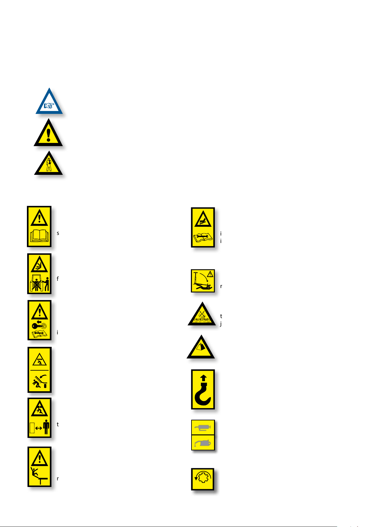
2.1 SAFETY SYMBOLS ........................................................................................................................................................................ 6
2.2 GENERAL SAFETY INSTRUCTIONS ........................................................................................................................................... 7
2.3 LOADING AND UNLOADING INSTRUCTIONS......................................................................................................................... 8
3. GENERAL DESCRIPTION............................................................................................................................................. 9
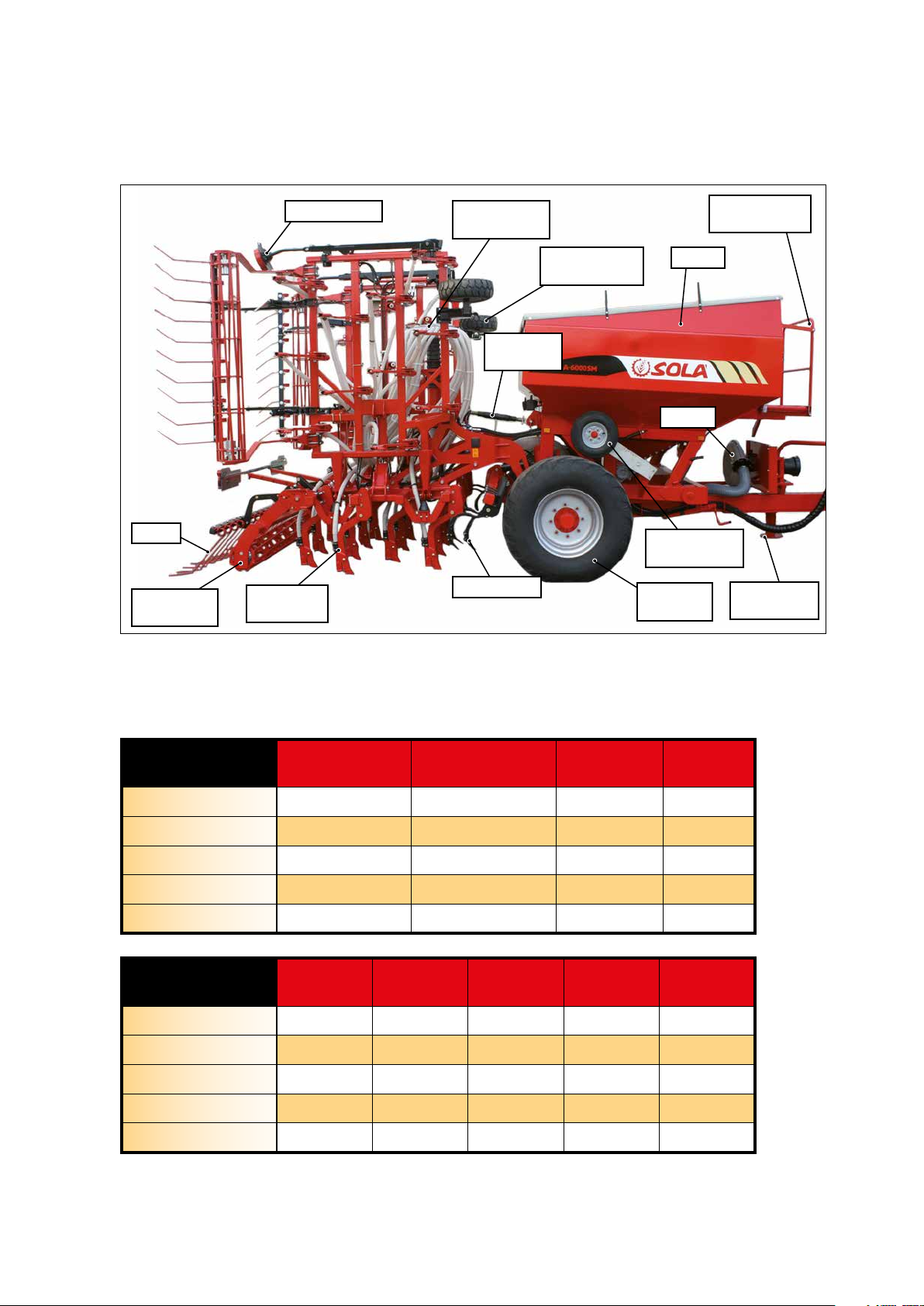
3.1 OVERVIEW OF THE MACHINE .................................................................................................................................................... 9
3.2 TECHNICAL SPECIFICATIONS .................................................................................................................................................... 9
3.3 IDENTIFICATION OF THE MACHINE ....................................................................................................................................... 10
3.4 USAGE ACCORDING TO DESIGN ............................................................................................................................................. 10
4. FUNDAMENTAL CONCEPTS FOR PLANTING .............................................................................................................11
4.1 TERRAIN....................................................................................................................................................................................... 11
4.2 SEED ............................................................................................................................................................................................. 11
4.3 DEPTH.......................................................................................................................................................................................... 11
5. COMMISSIONING ......................................................................................................................................................12
5.1 COUPLING THE SEED DRILLER TO THE TRACTOR................................................................................................................ 12
5.2 COUPLING AND ADAPTING THE PTO SHAFT ....................................................................................................................... 14
5.3 HYDRAULIC SYSTEM................................................................................................................................................................. 15
5.4 TRANSPORTATION POSITION.................................................................................................................................................. 16
5.5 LOADING AND UNLOADING THE HOPPER ........................................................................................................................... 17
5.6 SUPPORT FEET............................................................................................................................................................................ 18
5.6.1 FRONT SUPPORT FOOT............................................................................................................................................ 19
5.6.2 REAR SUPPORT FOOT .............................................................................................................................................. 19
5.7 PARKING BRAKE......................................................................................................................................................................... 20
5.8 END OF MACHINE WORK ......................................................................................................................................................... 20
6. ADJUSTMENTS ......................................................................................................................................................... 21
6.1 MACHINE LEVELLING ................................................................................................................................................................ 21
6.1.1 TOW-BAR AND TRACTOR LEVELLING .................................................................................................................... 21
6.1.2 SOWING EQUIPMENT LEVELLING .......................................................................................................................... 22
6.2 DEPTH CONTROLS..................................................................................................................................................................... 22
6.2.1 DEPTH TINES.............................................................................................................................................................. 22
6.2.2 DEPTH CONTROL WHEELS...................................................................................................................................... 23
6.2.3 COULTERS................................................................................................................................................................... 23
6.2.3.1 SM MODEL................................................................................................................................................. 24
6.2.3.2 NS-PLUS MODEL ...................................................................................................................................... 25
6.3 DOSAGE....................................................................................................................................................................................... 25
6.3.1 VOLUMETRIC DISPENSER ........................................................................................................................................ 26
6.3.1.1 NORMAL SEEDS (N position) .................................................................................................................. 26
6.3.1.2 SMALL SEEDS (F position)....................................................................................................................... 27
6.3.2 ROLLER DISPENSER .................................................................................................................................................. 28
6.3.3 DISPENSERS FOR FERTILIZER AND/OR MICROGRANULATE KITS.................................................................... 29
6.3.3.1 INTERNAL KIT HOPPER - FERTILIZER AND/OR MICROGRANULATE DISPENSER .......................... 30
6.4 SEED DOSAGE ADJUSTMENT .................................................................................................................................................. 31
6.5 SEED FLOW PRE-TESTING ........................................................................................................................................................ 32
6.5.1 MODELS WITH MECHANICAL TRANSMISSION ...................................................................................... 32
6.5.2 MODELS WITH ISOBUS ELECTRICAL TRANSMISSION .......................................................................... 34
6.6 SEED DOSE FIELD TESTING...................................................................................................................................................... 37
6.7 HARROW...................................................................................................................................................................................... 38
6.8 TRACK ERASERS (OPTIONAL).................................................................................................................................................. 38
6.9 COMPACTING ROLLER .............................................................................................................................................................. 39
6.10 HYDRAULIC TRACK MARKERS............................................................................................................................................... 40
6.10.1 TRACK MARKER LENGTH ADJUSTMENT............................................................................................................. 40
6.10.2 TRACK MARKER DISC INCLINATION ADJUSTMENT.......................................................................................... 41
6.11 INCLINATION OF FOLDING PARTS........................................................................................................................................ 41

- 4 -- 4 -
7. DISTRIBUTION TYPE................................................................................................................................................. 42
7.1 WITH MECHANICAL DRIVE TURBINE ...................................................................................................................................... 42
7.2 WITH HYDRAULIC DRIVE TURBINE......................................................................................................................................... 43
8. SOWING ELECTRONIC CONTROL.............................................................................................................................. 44
8.1 CONTROL PANEL, DESCRIPTION.............................................................................................................................................44
8.2 RUNNING SPEED -C1................................................................................................................................................................. 45
8.3 TOTAL AREA / SEED DRILLER WIDTH - C2 ............................................................................................................................. 45
8.4 CONTROL PANEL WITH TRACK MARKER (OPTIONAL)........................................................................................................ 46
8.5 ROAD TRACKING - C3................................................................................................................................................................ 46
8.6 TURBINE ROTATIONAL SPEED/ TURBINE ALARM - C4........................................................................................................ 50
8.7 DISTRIBUTOR SHAFT - C5......................................................................................................................................................... 50
8.8 HOPPER LEVEL ALARM - C6 ..................................................................................................................................................... 51
8.9 TOTAL SEEDING CUT OFF (OPTIONAL).................................................................................................................................. 51
8.10 EXIT CLOSING AT FOLDING PARTS (OPTIONAL) ................................................................................................................ 52
9. MAINTENANCE ......................................................................................................................................................... 53
9.1 SERVICE FREQUENCY ................................................................................................................................................................ 54
9.2 SEED DRILLER CLEANING......................................................................................................................................................... 55
9.3 TYRE PRESSURE ......................................................................................................................................................................... 55
9.4 LUBRICATION AND GREASING................................................................................................................................................ 56
10. DOSAGE CHART ...................................................................................................................................................... 57
10.1 SEED CHART.............................................................................................................................................................................. 57
10.2 ROLLER DISPENSER CALIBRATION FACTOR TABLE .......................................................................................................... 59
10.3 TABLES FOR CONVENTIONAL OR MICROGRANULATE FERTILIZER KITS ...................................................................... 60
10.3.1 INTERNAL KIT HOPPER WITH MECHANICAL TRANSMISSION ....................................................................... 60
10.3.2 INTERNAL KIT HOPPER WITH ISOBUS................................................................................................................. 60

- 5 -- 5 -
1. INTRODUCTION
It is essential to READ AND FOLLOW THE INSTRUCTIONS
AND RECOMMENDATIONS in this manual before operating
the SEED DRILLER A-6000. Careful reading enables maxi-
mum operator eciency, prevents accidents and damage,
and increases the seed driller’s capacity and life expectancy.
Please ensure that this manual has been read by any person
involved in performing operational tasks, (including prepa-
ration, dealing with mechanical problems and supervising
the machine), maintenance (inspection and technical assis-
tance) and transport.
For your safety, please follow these technical safety instruc-
tions as SOLÀ will not be responsible for damages caused by
not observing the information provided.
In the rst chapters you will nd the Technical Characteris-
tics and Safety Instructions, as well as some essential sowing
concepts. Basic concepts that are required to operate the
machine are explained in the Starting and Maintenance sec-
tions.
The last part of this manual consists of Dosage Tables, detai-
led by seed and fertilize type.
MAQUINARIA AGRÍCOLA SOLÀ
RESERVES
THE RIGHT TO MODIFY ILLUSTRATIONS, TECH
NICAL DATA AND TECHNICAL SPECIFICATIONS
AT ITS DISCRETION.

- 6 -- 6 -
On the machine, you will nd the following symbols:
Read the instructions carefully and observe the
safety advice given in the operating manual.
During the coupling manoeuvre, stay away
from the rear part of the tractor. Risk of serious
physical injury.
During maintaining or repairing the seed drill,
you must stop the tractor’s engine completely,
it must not be started.
Never stand under the sowing equipment, or
within its operation area. Risk of serious physi-
cal injury.
Risk of being crushed when working under the
machine, please secure the machine to prevent
this risk.
Never use the ladder to access the platform
when the machine is running. It is forbidden to
ride on the machine during operation. Risk of
serious physical injuries.
Danger of infection from escaping hydraulic
uid at high presure! This can inict serious
injuries with potentially fatal consequences if
it passes through the skin and into the body.
Keep the hose lines in good condition. Risk of
serious physical injuries.
Never stand under track markers or in their ope-
rational area. Risk of serious physical injuries.
Do not insert your hand into the hopper while
the drive wheels are turning. Risk of serious in-
jury.
Respect the maximum load.
Coupling point for transport by crane.
Keep the machine parts showing these lubrica-
tion and greasing symbols in good conditions
and greased. See section 9.4 LUBRICATION AND
GREASING POINTS
PTO shaft’s speed and turning direction (only in
machines with mechanical fans).
Kg. Max.
1000 rpm
2. SAFETY INSTRUCTIONS
2.1 SAFETY SYMBOLS
In this operating manual you will nd three dierent symbols relating to safety:
To facilitate operation with the seed drill.
To avoid damages on the seed drill or in the optional equipments.
This symbol warns of the risk of injury.

- 7 -- 7 -
2.2 GENERAL SAFETY INSTRUCTIONS
- Before starting the machine, please check the
machine is in good condition for work and is
safe for road use.
- Check that visibility is clear around the ma-
chine and there is no person in the working
area.
- In thoroughfare, please observe trac signs
and regulations.
- It is forbidden to ride on the machine or
climb into the machine when it is running.
- Before using the machine, the user must be
familiar with all operating
elements.
- Please be extremely careful when coupling
and uncoupling the machine to the tractor.
- Please check that the PTO shaft is in good
condition and well protected. Prevent the
protective tube from turning by holding both
the tube and chain provided for this purpo-
se.
- Mount the PTO shaft’s transmission only when
the tractor’s engine is o.
- Before connecting the PTO shaft, be sure that
the danger zone surrounding the machine is
clear.
- Never leave the tractor’s driver’s seat while the
machine is in operation.
- Do not deposit external elements inside the
hopper.
- When mantaining the hydraulic system of the
seed driller, make sure that it is depressurised
and the tractor’s engine is o.
- Please regularly check the condition of the
tubes and hosepipes in the hydraulic system.
These parts age naturally and their life should
not surpass 6 YEARS. Please replace when ne-
cessary.
- When transiting with the sowing equipment
raised, block the lowering switch. Before lea-
ving the tractor, lower the support feet, lower
the sowing equipment onto the ground and
remove the tractor’s starting key.
- Always use enough supporting elements
when maintaining the machine in a raised po-
sition to prevent the machine from lowering
or falling.
- Before planting, evaluate the potential risks
in the area such as very steep slopes, possi-
ble contact with overhead power lines due to
uneven oors and/or conguration of moving
parts of the machine.

- 8 -- 8 -
2.3 LOADING AND UNLOADING INSTRUCTIONS
THESE OPERATIONS SHOULD BE PERFORMED
ONLY BY QUALIFIED AND EXPERIENCED PER-
SONNEL.
LOADING AND UNLOADING THE MACHINE MUST
BE PERFORMED, IF POSSIBLE, USING A BRIDGE
CRANE.
WHEN THE PLANTER IS DELIVERED, IT SHOULD
BE IMMEDIATELY CHECKED TO DETECT POSSI-
BLE DAMAGES DURING TRANSPORTATION OR
MISSING PIECES. ONLY THE IMMEDIATE REPOR-
TING OF THIS TO THE DELIVERER WILL RESULT
IN COMPENSATION.
WARNING: SEE SECTION 3.2, TECHNICAL
CHARACTERISTICS, FOR KNOWING THE LOAD
THAT THE BRIDGE CRANE SHALL SUPPORT
The images show the towrope arrangements and mooring
points for this operation:
-
Front: A towrope located at the internal front part of the
hopper (Fig. 2.2).
-
Rear: two towropes located at the sowing equipment
sub-chassis (Fig. 2.3).
Fig. 2.3
Fig. 2.2
Fig. 2.1

- 9 -- 9 -
3. GENERAL DESCRIPTION
3.1 OVERVIEW OF THE MACHINE
Fig. 3.1
TRANSMISSION
WHEEL
TURBINE
FRONT
SUPPORT FOOT
FLOATING
WHEEL
HOPPER
ENTRY
LADDER
TRACK ERASER
COULTERS
HARROW
TRACK MARKERS
DEPTH CONTROL
WHEEL
DISTRIBUTION
HEAD
COMPACTING
ROLLER
LEVEL
TENSIONER
3.2 TECHNICAL SPECIFICATIONS
MACHINE TYPE
AND OF COULTERS
DISTANCE BETWEEN
COULTERS (cm)
HOPPER CAPACITY
(litres)
ESTIMATED
WEIGHT (kg) WHEELS
600/37 SM 16 5500 4600 560/45R22.5
700/43 SM 16 5500 5000 560/45R22.5
600/43 NS PLUS 14 5500 4500 560/45R22.5
600/48 NS PLUS 12,5 5500 4550 560/45R22.5
700/48 NS PLUS 14,6 5500 4700 560/45R22.5
MACHINE TYPE
AND OF COULTERS
MINIMUM
POWER (CV)
WORK WIDTH
(m)
TRANSPORT
WIDTH (m)
MAXIMUM
HEIGHT (m) LENGTH (m)
600/37 SM 150 6 3 3,1 7
700/43 SM 150 7 3 3,6 7
600/43 NS PLUS 150 6 3 3,1 7
600/48 NS PLUS 150 6 3 3,1 7
700/48 NS PLUS 150 7 3 3,6 7

- 10 -- 10 -
3.3 IDENTIFICATION OF THE MACHINE
All the machines have an IDENTIFICATION PLATE on the
frame, specifying:
MAQUINARIA AGRÍCOLA SOLÀ RESERVES
THE RIGHT TO OBTAIN AUTHORISATION OF ITS
EQUIPMENTS IN ANY MARKET IT CONSIDERS
NECESSARY.
Fig. 3.2Fig. 3.2
SERIAL NUMBER
YEAR
Fig. 3.3Fig. 3.3
SERIAL NUMBERSERIAL NUMBER
3.4 USAGE ACCORDING TO DESIGN
The A-6000 seed driller has been designed for sowing of ce-
reals and other kind of grain seeds.
The machine has been designed for being dragged by an
agricultural tractor.
If the machine is damaged due to other uses than the above,
the manufacturer will not be held responsible (see section
11. WARRANTY).
All legal provisions relating to machine safety, trac, and
health and safety at work shall be respected.
The changes made by the user override the manufacturer’s
guarantee for any damage or injury (see section 11. WAR-
RANTY).
Avoid using wet seeds; their use may cause clogging.

- 11 -- 11 -
4. FUNDAMENTAL CONCEPTS FOR PLANTING
4.1 TERRAIN
The better terrain conditions, the better the sowing quali-
ty. A good labour cannot be carried out in big clods or very
uneven furrows. Although SOLÀ machines resist harsh con-
ditions, if the seedbed does not satisfy the appropriate con-
ditions, then the sowing quality will be poor.
4.2 SEED
It is essential to use clean, quality seeds and, in the case of
barley, the seed must be deburred.
4.3 DEPTH
Seed planting depth aects tillering, the plant’s strength,
and its ability to resist frostbite or drought: the tillering node
is always 1 or 2 cm under the surface, regardless of the seed
planting depth.
Planting deeper does not mean getting deeper roots. Only
a few roots grow from the lower part of the seed. Most of
them grow from the tillering node closer to the ground level.
Sowing at normal depth: from 2 to 4 cm
Fig. 4.1Fig. 4.1
SeedSeed
TilleringTillering
nodenode
• Thick stem, short rhizome
and good resistance to ice.
• Multiple tillering of 3 to 6
tiles and many leaves, be-
tween 6 and 10.
• Big rooting, 5 cm in width
and 10-12 cm in depth.
• More sprigs are obtained
with fewer grains per sow-
ing square meter.
Deeper sowing: between 5 and 6 cm
Fig. 4.2Fig. 4.2
SeedSeed
RhizomeRhizome TilleringTillering
nodenode
• Thin stem, ice-exposed
rhizome
• Late and poor tillering, 1
or 0 tiles and few leaves, 3
or 4 approx.
• Regular rooting, 3 cm in
width and 5 cm in depth.
• More grain per square
meter is necessary to ob-
tain the same sprigs as in
the rst case.
Too deep sowing: from 8 to 10 cm
Fig. 4.3Fig. 4.3
RhizomeRhizome
SeedSeed
TilleringTillering
nodenode
• Very thin stem. Not tiller-
ing and one leaf.
• Grain reserves exhaust in
a large rhizome that the
ice can easily cut.
• Poor rooting, 1 cm in
width and 3 cm in depth.
• The double amount of
grain per square meter is
necessary to obtain the
same sprigs as in the rst
case.
IMPORTANTE: THE SOWING DEPTH ON TINE
COULTERS SEED DRILL ISN’T UNIFORM, IT DE-
PENDS ON THE CONDITIONS OF HOMOGENIZA-
TION CONDITIONS AND FIELD CHARACTERISTICS.
IN VERY COLD PLACES, REPEATED FROSTBI-
TE CAN PRODUCE A BULKING EFFECT ON THE
GROUND’S MOST SUPERFICIAL LAYER WITH
THE RISK OF LOOSENING AT THE PLANT’S IN-
CIPIENT ROOTS, CAUSING THE PLANT TO DIE.
IN THESE CASES, IT WOULD BE ADVISABLE TO
PLANT SLIGHTLY DEEPER AND, IF POSSIBLE, TO
USE THE ROLLER FOR COMPACTING THE SOIL
AND BETTER PROTECT THE SEEDS.
WHEN STARING THE MACHINE, THE FIRST ME-
TER OF FURROWS WILL NOT CONTAIN ANY
SEED. ON THE CONTRARY, WHEN STOPPING
THE MACHINE, THE SEEDS THAT WERE ALRE-
ADY FALLING THROUGH THE HOSES WILL SLI-
DE FROM THE MACHINE AND END UP PILED IN
THE LAST METER. CONSIDER THIS IN ORDER TO
ACHIEVE A GOOD RESULT.
ALWAYS WORK AT UNIFORM SPEED. SUDDEN
ACCELERATING AND BRAKING WILL CAUSE AN
IRREGULAR SEED DISTRIBUTION.
RECOMMENDED SEEDING DEPTH CHANGES
DEPENDING ON THE TYPE OF CROP, THEREFO
RE, IT IS RECOMMENDED THE PROFESSIONAL
ADVICE TO THE FARMER ON THISMATTER.

- 12 -- 12 -
5. COMMISSIONING
The issues to take into account before starting the machine
are detailed below:
• Verify that the mechanical components are well greased.
Periodically grease the mechanical components (see sec-
tion 9.4 LUBRICATION AND GREASING POINTS).
• Verify the tyre pressure (see section 9.5 TYRE PRESSURE).
• Check that the machine’s hydraulic circuit pipes and ho-
ses and the compressed air lines (product transport) are in
good condition.
• Check the cable layout and that the connectors are rmly
coupled.
After coupling the seed driller with the tractor:
• Verify that the machine is correctly attached to the tractor.
• Before starting the machine, get familiar with all its compo-
nents and adjustments.
• Start the machine being empty in order to free the con-
ducts form any condensation of water or possible dirt.
• Adjust the machine and all its components, the type of ter-
rain and the seed.
5.1 COUPLING THE SEED DRILLER TO THE
TRACTOR
The A-6000 seed driller is tted with a rotating shaft-ring
hook.
MAKE SURE THAT NOBODY AND NOTHING IS
BETWEEN THE TRACTOR AND THE SEED DRILL-
ER WHEN COUPLING AND UNCOUPLING.
THESE PROCEDURES REQUIRE PAYING MAXI-
MUM ATTENTION TO AVOID DAMAGE TO THE
OPERATOR.
MACHINE COUPLING AND UNCOUPLING PRO-
CEDURES MUST BE CARRIED OUT WITH THE
SUPPORT FEET AT THEIR LOWEST POSITION.
Follow the steps below for the coupling manoeuvre:
1- Plug in the hydraulic circuit connectors of the machine
to the tractor distributor, for:
1.1- FOLDABLE PARTS OF THE SOWING EQUIPMENT
1.2-TRACK MARKERS
1.3-SOWING EQUIPMENT AND TRACK ERASER
1.4- HYDRAULIC TURBINE
1.5- HYDRAULIC SERVICE BRAKE
THE NECESSARY HYDRAULIC CONNECTIONS
FOR THESE ELEMENTS ARE SPECIFIED IN SEC-
TION 5.3 HYDRAULIC SYSTEM.
FOR MACHINE VERSIONS WITH HYDRAULIC TUR-
BINE, PTO SHAFT MUST BE ADAPTED ONCE THE
MACHINE IS COUPLED TO THE TRACTOR (SEE
SECTION 5.2 COUPLING AND ADAPTING THE PTO
SHAFT).

- 13 -- 13 -
2- Plug in the electrical connector for the lightning
equipment.
3-
Place the front support feet in vertical position (see sec-
tion 5.6 SUPPORT FEET).
4-
Lower the central sowing equipment until touching
the ground.
5- Hook the seed drill rotatory ring to the tractor at the
towing hook point. (Fig. 5.1).
Fig. 5.1
IF THE HOOK POINT IS TOO LOW, SEE
SECTION 6.1.1 TOWBAR AND TRACTOR
LEVELLING.
6- Lift the machine support foot.
BEFORE MOVING THE MACHINE,
MAKE
SURE IT IS CORRECTLY HOOKED TO THE
TRACTOR.
FOR
UNCOUPLING THE MACHINE AND THE
TRACTOR, PERFORM THE STEPS IN THIS SEC-
TION INVERSELY.
The machine has electrical connections for:
• SIGNALLING LIGHTS and WORK LAMPS.
• CONNECTION TO ISOBUS (depending on the model).
WORK LAMPS
The machine has swivelling work lamps located at the rear of
the frame. Press the button to turn the lamps on or o (Fig. 5.2).
Fig. 5.2Fig. 5.2
SIGNALLING LIGHTS
All models have a 7-pin connector for the signalling lights.
Layout and table of the 7-pin connector (according to ISO
1724):
1
5
4
7
6
3
2
Pin
no. FUNCTION
1Left turn signal
2NOT USED
3Ground
4Right turn signal
5Right position light
6Brake
7Left position light
ISOBUS
The machine must have the 9-pin con-
nector to connect to the tractor’s ISOBUS
(according to ISO 11783).
3
8
7
1
2
6
4
59
MAKE SURE THAT THE WORK LAMPS ARE TUR-
NED OFF WHEN TRANSPORTING THE MACHINE
ON PUBLIC HIGHWAYS.

- 14 -- 14 -
5.2 COUPLING AND ADAPTING THE PTO
SHAFT
Once the seed driller is coupled to the tractor, the TRANS-
MISSION MUST BE ADAPTED for the equipment with me-
chanical turbine. In order to do so, it is necessary to:
1- Dismantle and introduce one end in the PTO and the other
end in the seed driller. Therefore, introduce the PTO shaft
into the threaded shaft in both machines, maintaining the
security plug pressed, release the plug and move the PTO
shaft back until hearing a click sound; this sound means
that the plug is in its corresponding receptacle.
ASSEMBLY HOMOKINETIC PTO SHAFT INTO
THE TRACTOR PTO.
ALWAYS HANDLE THE TRANSMISSION WITH
THE ENGINE OFF. ALWAYS WORK WITH THE
TRANSMISSION PROTECTED AND IN GOOD
CONDITIONS. AVOID ANY ROTATION IN THE
TRANSMISSION PROTECTION TUBE BY FIXING
IT WITH THE CHAIN.
2- Determine the minimum shift length “L” (Fig. 5.3), By lif-
ting and lowering the hydraulic lift.
Fig. 5.3
3- Cut the plastic and metal surplus parts with the same size
and reassembly the transmission (Fig. 5.4).
Fig. 5.4
Fig. 5.5
4- Activate the seed driller lift
and verify that the trans-
mission shift is correct.
5- Secure the PTO shaft to the
tractor by means of the -
xing chain (Fig. 5.5).
PREVENT THE TRANSMISSION FROM WORKING
IN A VERY STEEP INCLINATION ANGLE (MAX.
35º).
COUPLE THE TRACTOR PTO SMOOTHLY SUD-
DEN ACCELERATION CAN RESULT IN SERIOUS
DAMAGE TO THE SEED DRILLER.

- 15 -- 15 -
5.3 HYDRAULIC SYSTEM
The machine requires hydraulic connexion for:
• FOLDING AND UNFOLDING THE FOLDABLE PARTS OF THE
SOWING EQUIPMENT. One double discharge
• FOLDING AND UNFOLDING THE TRACK MARKERS: One
double discharge
• LOWERING AND LIFTING THE SOWING EQUIPMENT AND
TRACK ERASER (optional). One double discharge with key
for removing the track eraser.
• HYDRAULIC TURBINE One double discharge
• HYDRAULIC SERVICE BRAKE One simple discharge
Hydraulic circuits can be distinguished by their colours ac-
cording the following chart:
TAP
COLOUR DESCRIPTION
BLUE Hydraulic system for trackers
GREEN Hydraulic system for folding the sowing
equipment.
RED Hydraulic system for service brake and turbine
(only for versions with hydraulic turbine)
YELLOW Hydraulic system for lifting the sowing equip-
ment and track erasers.
Two ow regulators (Fig. 5.6) help the hydraulic fol-
ding and unfolding processes to be carried out smoo-
thly:
Each hydraulic system has
one regulator for each
operation, which must be
adjusted according to the
hydraulic ow supplied
by the tractor. It is advisa-
ble to star the operation
with the regulator almost
closed for preventing fast
unfolding that may cause
damage to the seed driller.
Fig. 5.6
Fig. 5.7
OPEN
CLOSED
For machine versions with track eraser, this element can be
excluded with the stopcock (Fig. 5.7) placed between the
hopper and the seed drill. See the stopcock positions in the
images, being: OPEN: for including the track eraser, and
CLOSED: for excluding the track eraser.
The machine also includes security locks (1, Fig. 5.8) that
must be used for securing the lateral equipment while the
machine is transported. The image shows the trigger in
locked position.
Fig. 5.8Fig. 5.8
1
2
IF THE FOLDABLE PARTS DO NOT DESCEND
WHEN PRESSURING THEIR HYDRAULIC CIR-
CUIT, MAKE SURE THAT THE SECURITY LOCKS
ARE UNLOCKED (1, Fig. 5.8). OTHERWISE, FOLD
THE EQUIPMENT AGAIN AND ADJUST THE
FOLDING STOPS (2, Fig. 5.8).
WHEN OPENING OR CLOSING THE FOLDING
PARTS AND THE TRACK MARKERS, MAKE SURE
THAT NOBODY AND NOTHING IS NEAR THE
MACHINE OR ALONG THE TRAJECTORY OF THE
MOVABLE PARTS.
ALWAYS PERFORM MACHINE MAINTENANCE
WORKS WITH THE HYDRAULIC CONNECTIONS
UNPLUGGED.
KEEP THE HYDRAULIC HOSE LINES IN GOOD
CONDITION. THE PRESSURE OIL CAN PENE-
TRATE THE SKIN CAUSING SERIOUS INJURIES.
USE ONLY THE HYDRAULIC HOSE LINES PRO-
VIDED BY THE MANUFACTURER.

- 16 -- 16 -
5.4 TRANSPORTATION POSITION
With the machine coupled with the tractor and the hydraulic
circuits connected to the tractor distributor, follow the steps
below for transporting the machine:
Fig. 5.9
1- Fold the track markers.
2- Fix the COMPACTING ROLLERS; in order to do so, place the
bolts (A, Fig. 5.10)
3- Lift the lateral equipment and make sure that the security
locks are locked (Fig. 5.11).
Fig. 5.11Fig. 5.11Fig. 5.10Fig. 5.10
A
4- If the track eraser is down, make sure that its stopcock is
open.
5- Lift the seed drill and track eraser up to their maximum
position.
AVOID THE MOVEMENT OF THE MOVABLE ELE-
MENTS.
AFTER FOLDING THE MACHINE, AND BEFO-
RE TRANSPORTING IT, MAKE SURE THAT THE
TRACK ERASER HAS BEEN LIFTED; OTHERWISE,
VERIFY THAT THE STOPCOCK IS OPENED AND
REPEAT THE PREVIOUS STEPS IN THIS SECTION.
ACCORDING WITH THE WORKING CONDITIONS
DEFINED BY THE FINAL USER AND THE OPTIONS
INCORPORATED, THE MACHINES COULD NOT
MEET THE REQUIREMENTS STABLISHED BY THE
LAW TO TRANSPORT THEM ON PUBLIC ROADS.
THE COMPLIANCE OF THE LAW IS STRICTLY
RESPONSIBILITY OF THE FINAL USER OF THE
MACHINE. MAQUINARIA AGRÍCOLA SOLÁ S.L.
DENIES ANY RESPONSIBILITY DERIVED OF
NON-COMPLIANCE OF THE REGULATIONS ON
THE COUNTRIES WHERE THEIR PRODUCTS ARE
DESTINED TO.
IMPORTANT: THE OFFICIALLY APPROVED
HOOKS FOR TRAVELLING ON PUBLIC HI-
GHWAYS ARE THE RING HOOKS. THE OTHER
HOOKS ARE PROVIDED SOLELY FOR OFFROAD
USE ON FARMLAND. USE OF THESE HOOKS IS
STRICTLY AT THE USER’S SOLE LIABILITY.
The braking system has a valve located at the front of the
machine. This valve is regulated by a lever (Fig. 5.12), that
should be placed in the right posiltion according to the level
of lling of the hopper.
Position 1/1 - with the hopper full of product.
Position 1/2 - with the hopper at half capacity.
Position 1/4 - with the hopper empty or with very little product.
Fig. 5.12Fig. 5.12
WARNING: THE INCORRECT USE OF THIS DE-
VICE CAN BE DANGEROUS AND GENERATE AN
UNSUITABLE BRAKING OF THE VEHICLE. WITH
THE CONSEQUENT RISKS THAT THIS ENTAILS.

- 17 -- 17 -
5.5 LOADING AND UNLOADING THE
HOPPER
For a safe and fast hopper load, the best option is using a
screw conveyor. An hydraulic crane can also be used for lift-
ing the BIG BAG and put it on top of the hopper for coupling
it; follow the manufacturer instructions.
IMPORTANT: BEFORE EMPTYING THE HOP-
PER, MAKE SURE THAT NOTHING REMAINS IN-
SIDE THE HOPPER.
BEFOREFILLING THEHOPPER, MAKESURE THAT
THE EMPTYING TRAP DOORS ARE CLOSED.
For FILLING the hopper:
1- Pull the lock (1, Fig. 5.13) for releasing the hopper landing,
then move the ladder until it reaches the horizontal posi-
tion.
Fig. 5.13Fig. 5.13
1
Fig. 5.14 2
2-
Remove the locking pin (2, Fig. 5.14) and slightly pull the
ladder upwards for releasing the locking point (indication,
Fig. 5.14).
3- Pull the ladder horizontally up to the end of its trajectory.
Then, move it until it reaches the vertical position and the
stop end (Fig. 5.15).
4- Remove the fastening rubber bands of the canvas (Fig. 5.16).
Fig. 5.16
Fig. 5.15
5- Take the handle at the ladder side (Fig. 5.17) and place it
at the end of the canvas (Fig. 5.18). Turn the handle for re-
moving the canvas (Fig. 5.19).
Fig. 5.17Fig. 5.17
Fig. 5.19
Fig. 5.18
IF THE CANVAS CANNOT BE REMOVED, MAKE
SURE THAT ALL FASTENING RUBBER BANDS
HAVE BEEN REMOVED.
6- Fill the hopper with the seeds.
7- Once the hopper is full, close the canvas cover, keep the
handle, fold the access ladder and lock the locking pin.
FOLD THE STAIRS AFTER LOADING OR INSPECT-
ING THE HOPPER.
For EMPTYING the hopper:
1- Place a container or sack in front of the dispenser empty-
ing trap door (Fig. 5.20).
2- Turn the handle to the left for opening the trap door and
emptying the hopper (1, Fig. 5.20).
3- When nishing this task, close the trap door by turning
the handle to the right (1, Fig. 5.20)
Fig. 5.20
1
Close
Open

- 18 -- 18 -
For fast HOPPER EMPTYING:
1- Loosen the wing nut (2, Fig. 5.21).
Fig. 5.21
2
2- Slightly push on the trap door and move the screw and
the wing nut upwards (indication, Fig. 5.21).
3- Once the seeds stop falling, close the trap door placing
the screw and tightening the wing nut (Fig. 5.22).
Fig. 5.22
IF SEEDS DO NOT FALL, MAKE SURE THAT THE
SEED DISPENSED TAP IS OPENED (Fig. 5.22).
5.6 SUPPORT FEET
The machine is tted with a hopper support foot (see sec-
tion 5.6.1 FRONT SUPPORT FEET) and two feet for the sowing
equipment (see section 5.6.2 REAR SUPPORT FEET).
LIFT THE SUPPORT FEET BEFORE OPERAT-
ING THE MACHINE. IF THE SUPPORT FEET ARE
DOWN DURING OPERATION, THE EQUIPMENT
MAY BE DAMAGED.
HANDLE THE SUPPORT FEET WITH THE MA-
CHINE COUPLED TO THE TRACTOR.

- 19 -- 19 -
5.6.1 FRONT SUPPORT FOOT
The front support foot is located at the hopper tow-bar. For
LOWERING the support foot:
Fig. 5.24
1
2
Fig. 5.23
2
1
1- Remove the crank fastening chain (1, Fig. 5.23)
2- Hold the support foot with one hand and remove
the security pin with the other hand (2, Fig. 5.23).
3- Place the support foot in vertical position and
place the security pin (2, Fig. 5.24) for xing its
position.
4- Adjust the foot height with the crank (1, Fig. 5.24)
and fasten the crank with the chain (Fig. 5.24).
For LIFTING the support foot:
1- Remove the crank fastening chain (1, Fig. 5.24)
and the security pin (2, Fig. 5.24).
2- Lift the support foot up to reaching the horizon-
tal position (Fig. 5.23) and place the security pin
(2, Fig. 5.23).
3- Place the crank fastening chain (1, Fig. 5.23)
5.6.2 REAR SUPPORT FOOT
Fig. 5.25Fig. 5.25
B
A
The rear support feet are locat-
ed in the sowing equipment.
For LIFTING or LOWERING the
support foot:
1- Remove the security pin (A,
Fig. 5.25) and the bolt (B, Fig.
5.25) for releasing the foot.
2-
Move the support foot until
reaching the desired position.
3- Place the security pin (A, Fig.
5.25) and the bolt (B, Fig.
5.25) for xing the foot.

- 20 -- 20 -
5.7 PARKING BRAKE
Turn the lever to the right for activating the parking brake
and, turn it to the left for releasing.
Fig. 5.26
BEFORE SOWING, MAKE SURE THAT THE PARK-
ING BRAKE IS RELEASED (WITHOUT BLOCKING
THE FLOATING WHEELS)
5.8 END OF MACHINE WORK
• Fully empty the hopper of any seed and fertilizer:
• Wash the machine with compressed air, particularly the
containers used for chemical products (see section 9.2
SEED DRILLER CLEANING).
• Verify that the machine components are in good condition.
Substitute the worn components.
• Remove any particle that may produce corrosion. If neces-
sary, paint these areas with anticorrosive paint or varnish.
• Grease and lubricate the indicated parts, chains and trans-
mission gears (see section 9.4 LUBRICATION AND GREAS-
ING POINTS).
This manual suits for next models
1
Table of contents
Other Sola Seeder manuals