Gason SR Series User manual

A member of
COPYRIGHT
Neither this manual or part thereof may be reproduced or published without the prior permission of A.F. Gason Pty. Ltd.
1800 & 2000 SR SERIES AIR SEEDER
OPERATOR’S MANUAL
Covering the 1860, 1880/90 & 2120/50 Models
GPN 216593 REVISION - 10/09

Page Intentionally Blank

CONTENTS
Warranty Form
Introduction ........................................................
1
General Information ...........................................
3
Safety.................................................................
6
Specifications.....................................................
8
Conversions.......................................................
16
Bolt Specifications..............................................
17
Ordering Parts....................................................
18
Spare Parts Record............................................
19
Assembly Instructions........................................
20
Implement Hitch Systems...........................
21
Distribution System ....................................
25
Pre-Delivery Checklist................................
24
Transporting.......................................................
29
Operating the Air Seeder ...................................
30
Monitor Operation.......................................
31
Ground Drive Model
Monitor Introduction & Operation ...............
32
Calibration..................................................
34
Method A (using chart)......................
34
Method B (preferred) .........................
37
Method C (Wheel Circumference).....
38
Calibrating a 3 Bin Seeder.................
40
Variator Setting Guide .......................
41
Calibration Handle Turns...................
56
Area Rate Chart ...............................
57
Converting lb/acre to kg/ha................
58
Planting Details Reference................
59
Meter Drive System...........................
61
Variator Gearbox...............................
61
High sprocket Ratio...........................
63
VRT Hydraulic Drive Model
Introduction Operation................................
64
Monitor Operation.......................................
65
Manual Override.........................................
71
Calibration..................................................
74
Sprocket Ratio Selection Guide.........
78
Planting Details Reference................
89
Maintenance...............................................
91
Trouble Shooting........................................
93
Liquid Equipped Air Seeder
Introduction Operation................................
96
General Safety ...........................................
96
Operating Machine.....................................
97
Calibration..................................................
98
Trouble Shooting........................................
100

CONTENTS
Metering System
SR Meterbox Assembly Features ..............
103
Low/High Rates....................................
104
Reducing the Outlets............................
104
Large Seeds.........................................
105
Deep Banding.......................................
106
Triple Shooting .....................................
106
Removing Metershaft Assembly ................
108
Removing Meterwheels .............................
108
Blanking Metershft Housing.......................
110
Fitting Meterwheel Reduction Cover Plates
110
High / Low Sprocket Ratio..........................
111
Blocking Air Flow .......................................
111
Metering Oats ............................................
112
Fitting Broad Beans Metershaft Assy.........
112
Bearing Replacement in Nose Assy...........
113
Hydraulic System...............................................
114
Tractor Requirements ................................
114
Hydraulic Connections...............................
115
Disconnecting the Hyd. Hoses...................
116
Filter Maintenance .....................................
117
Blower Capacity.................................................
118
Blower Speed.............................................
120
Maximum Application Charts .....................
122
General Maintenance.........................................
126
Trouble Shooting ...............................................
129
Optional Attachments.........................................
129
Auger Operation ................................................
134
Storage and Cleaning........................................
136

INTRODUCTION Page 1
05/06
A.F. Gason Pty Ltd is an Australian owned
family business operating from within rural
Victoria. The Gason company has been
servicing the needs of rural Australians for
more than 60 years. We operate through a
local dealer support network that spans the
country. A.F. Gason’s would like to thank
you for purchasing your Australian made Air
Seeder, and trust that you will have many
years of trouble free service.
The Air Seeders have been designed
to be functional, practical and reliable. They
incorporate the latest technology in air
seeder design but retain their basic
functionality to ensure ease of
maintenance.
The Gason 1800 and 2000 range of
Air Seeders can perform a variety of
seeding operations and are available in
either a front tow (FT) or rear tow (RT)
model. There are a number of bin
capacities available with either 2 or 3 bin
configurations. A large range of sowing
outlet configurations are available, making
the Air Seeder adaptable to a variety of
implements to perform different tillage
practices.
The Gason metering system is a
positive and accurate method of placing seed
and fertilizer into the air stream. The system
is capable of sowing conventionally, often
referred to as single shooting (seed and
fertilizer together), deep banding (separating
the seed and fertilizer) or triple shooting
(handling 3 separate products through to the
implement). The system can also sow
summer and winter crops with minimal
adjustment.
This manual endeavors to provide the
owner with a complete understanding of the
Air Seeder’s operation and the processes
required to obtain the highest level of
performance possible. It is suggested that
the owner/operator read this manual and any
other literature that has been supplied with
your machine to ensure a safe and trouble
free operation.
References to the left and right hand sides of
the Air Seeder are from the rear of the
machine looking forward.
Fig. 1 1880RT Series Air Seeder.
While every effort has been made to ensure the accuracy of
the information in this manual, A. F. Gason Pty Ltd reserves
the right to delete, change or add information without notice.

Introduction
Page 2
02/07
Fig. 2 2150FT Series Air Seeder with Auger and rear walkway (optional).
Fig. 3 2150RT Series Air Seeder.

GENERAL INFORMATION
Page 3
02/07
Introduction
The Air Seeder uses the flow of air to
convey seed and fertilizer to each tine. This
type of material transfer is known as
pneumatic conveyance (refer Fig. G1).
The material being sown must be
metered accurately into the air stream to
deliver a constant application rate.
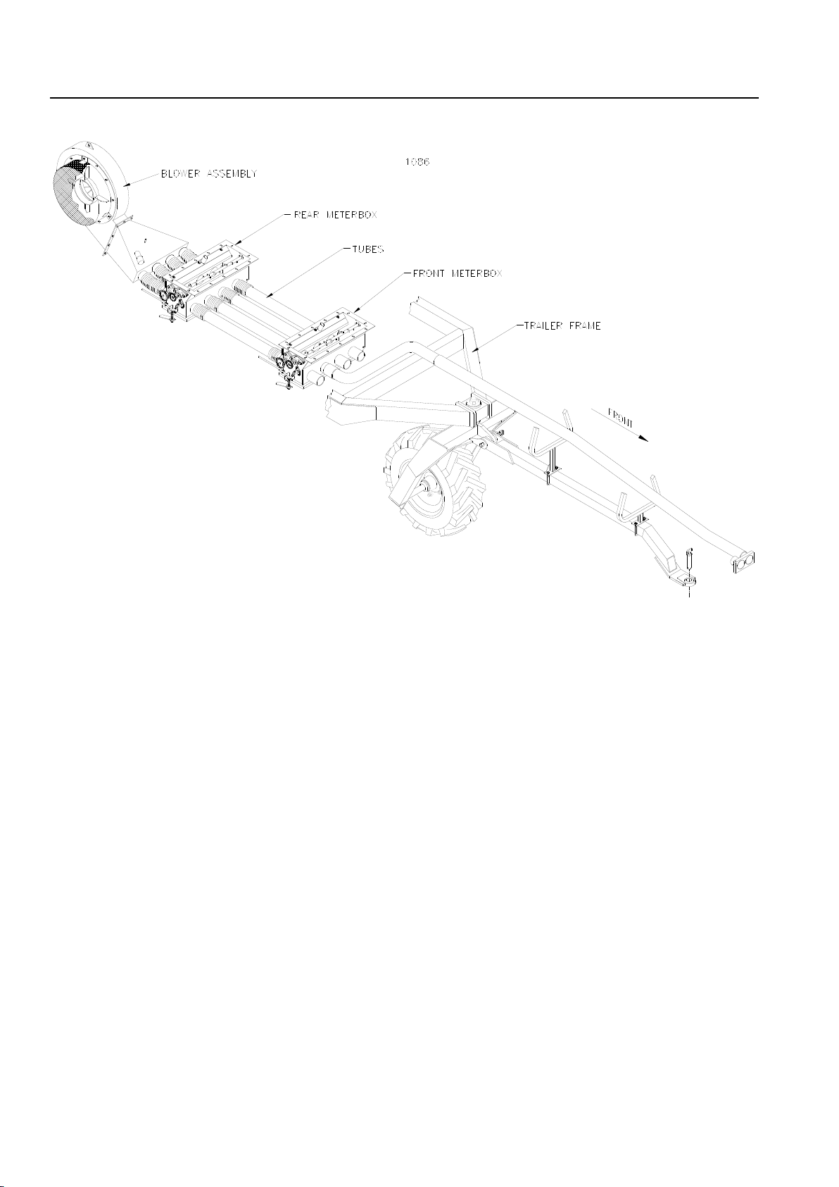
How the Air Seeder Operates
Seed and fertilizer are transferred from
pressurized bins to multiple conveying
tubes via separate meterboxes. A
meterwheel arrangement inside the
meterbox is rotated by either a ground
wheel (ground drive seeder) or hydraulic
motor (VRT equipped Seeder).
As the ground wheel rotates, so too does
the metering system. The metering system
can be disengaged or engaged at the tractor
cab.
A blower is located upstream of the
meterbox on the Air Seeder. It is used to
produce the airflow required to convey the
material.
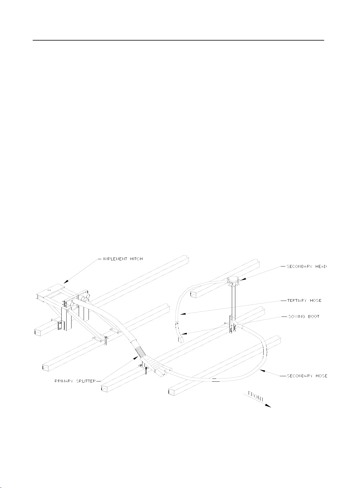
The seed and fertilizer is conveyed
towards the implement. It is then evenly
divided into smaller amounts as it passes
through the primary splitters.
The material then travels along the
secondary hoses to the secondary manifold
heads. It is distributed to the tertiary hoses
and transferred to the sowing boots mounted
on the tines.
Fig. G1 Two bin model shown.
1088
General Information
Page 4
02/07
Air Seeder Construction
The RT model air seeders trail behind
the implement while the FT models are
towed in front of the implement. The basic
operation of both designs is the same other
than the location of the seeder.
The RT models are supplied with all
components to attach to the rear of the
implement. Some modifications may be
required when fitting to non-Gason
implements but in most cases fitment is a
straight forward operation. The rear tow
models are also available with a rear hitch
system that attaches to the rear of the
seeder, which will allow a set of harrows or
light prickle chain to be towed.
The FT models are fitted with a roller
style rear hitch with which to pull the
implement. This hitch, when left unpinned,
dramatically reduces the load on the seeder
during turning which will help extend the life
of the machine. The trailer has also been
designed to withstand the high loads exerted
on the frame while pulling the implement.
In both cases, the seeders have been
designed to allow quick and easy
detachment from the implement and tractor.
The 1800 and 2000 air seeder range
has a folding ladder that is fitted to the left
hand side of the machine. The walkway is
set low and runs along the left side or
between the front and rear bins. This offers
a safe environment in which to fill the large
capacity machine.
The bins have been made from 2.5 and
3mm thick mild steel with folded corners,
which are fully welded, on both internal and
external joints.
The bins have been produced in two
halves and are painted using a high bake
enamel to reduce corrosion both inside and
out before joining. The bin halves are then
joined using structural quality rivets and
sealed with high-grade sealant. The sealant
Fig.G2 RT Model Air Seeder
shown fitted with
4 outlet meterboxes.
General Information
Page 5
02/07
can be replaced at any time, if required,
without splitting the bins.
The trailers are built from 350/450-
grade rectangular hollow section with either
side plates or truss system for stiffening. It
has been designed and tested to reduce
the possibility of rearing if unevenly loaded.
The metering system incorporates
nylon and stainless steel componentry in
areas affected by fertiliser induced
corrosion.
The output of the ground driven
metering system is controlled by a stepless
variable speed gearbox, which can easily
be adjusted. Each meter system has its
own separate adjustment. VRT equipped
seeders use individual hydraulic motors to
control metering rates.
The blower’s hydraulic system uses
quality components and will require minimal
maintenance. The system has been
designed to operate in a harsh environment.
It is fitted with a check valve to prevent
damage if incorrectly connected.
The blower is mounted on the trailer
frame and houses a high capacity impeller.
It has been specifically designed to operate
in the rough conditions that occur during
normal operation. The impeller is directly
mounted to the motor, which means that
there are no external bearings or an external
coupling.
Calibrating the ground driven metering
system has been simplified by providing a
chart with instructions to the side of the bin.
There is no need to calculate figures if
calibrating within average application rates.
A collection tray and an accurate scale
set is included with the Air Seeder.
For further information on individual
aspects of the seeder refer to the appropriate
section in this manual.
Fig. G3 Distribution System.
1087

SAFETY
Page 6
02/07
The Air Seeder has been designed
with safety in mind. However, the
equipment is only as safe as the person
operating it.
Do not operate the Air Seeder until
you have read and understood this manual.
If you feel you need help or advice on the
operation of the Seeder, contact your local
authorized Gason Dealer.
To ensure trouble free and safe
operation of your seeder, it is important to
carry out a daily safety check to reduce the
possibility of a costly breakdown.
Items to Check Daily During Operation
1. Check all wheel nuts are tight during the
first couple of days of seeding or after
transportation (refer page 17).
2. Check all tyre pressures and tyre
conditions in general. NOTE: a badly
worn rear drive tyre will affect the
metering accuracy.
3. Ensure the safety guard on the blower
unit is fitted.
4. Check all hydraulic breakaway
connections are locked into position.
5. Check all hydraulic hoses and fittings for
leaks.
6. Check all chains and sprockets for wear
or movement on the shaft.
7. Check metershafts turn freely before
operating each day or after transporting
when loaded (refer page 62).
8. Check draw bar pins for wear.
9. Ensure bin lids are closed and that there
are no air leaks when blower is
operating.
10.Check distribution hoses for damage or
kinks, especially after operating the wing
fold system on the implement.
General Safety Conditions
DO NOT ride on the machine when
operating.
DO NOT touch or attempt to adjust any
moving parts.
DO NOT adjust hydraulic fittings while
under pressure.
DO NOT remove any safety guards while
the seeder is operating.
DO NOT operate the machine unless all
safety guards are securely fitted.
DO carry out the daily safety checks and
operate the seeder in a safety conscious
manner.
Hydraulics
Before working on the hydraulic system
always check that the blower is not
operating, and that there is no pressure in
the hydraulic system.
Never attempt to disconnect a
breakaway coupling if the blower is
operating. Turn the tractor off if working on
the metering system of a VRT equipped
seeder.
Leaving the Air Seeder Unattended
Always close the bin lids and ensure
that no material is left in the bins after
seeding. Chock the Air Seeder wheels to
prevent it from rolling.
When Working on the Air Seeder
Place suitable stands under the trailer if
removing a wheel or carrying out major work.
Never enter the bin compartment
unless another person is present. Always
take proper safeguards if entering a bin or
working on components that have been
exposed to treated seed.
Wear ear protection if working near the
blower while operating.

Safety
Page 7
02/07
Transporting
Never transport the seeder with the
clutch switch engaged (ground drive
models).
Avoid transporting the seeder long
distances when loaded. Do not exceed
20km/h when towing the seeder when
loaded. Maximum speed for towing an
empty seeder is 40km/h. Use safety chains
where provided.
For further information and helpful tips
on transporting refer to the Transporting
section of this manual (refer page 29).
Lifting the Air Seeder
The Air Seeder has been supplied
with 2 lifting eyes located on the trailer
frame between the bins.
The 1860-2150 model seeders will
require a third front sling for lifting.
Ensure you have safe lifting
equipment with the correct capacity before
attempting to hoist the machine.
Fig. G4 2150RT fully assembled being lifted.
When lifting the seeder it is preferable
to use soft slings and shackles at the trailer.
If chains must be used ensure that the bins
are protected against paint damage.
Seeder Weight Unloaded
1860 model 2900kg approx.
1880 model 3300kg approx.
1890 model 3500kg approx.
2120 model 4900kg approx.
2150 model 5500kg approx.
Auger Operation and Safety
Refer to the Auger section of this manual.
Pasture Planter Operation and Safety
Refer to the Pasture planter Operators
Manual.
Fig. G5 Pasture planter fitted to a 1880FT.

SPECIFICATIONS –1860 SR SERIES
10/09
Page 8
Dimensions
1860FT
1860RT
Overall width
2500
2760mm
Overall height*
2870
2870mm
Top of bin height
2750
2750mm
Overall length^
6160
9485mm
Seeder length
6160
5740mm
Rear wheel centres
2000
2000mm
Front wheel centres
(CTC models)
-
2000mm
Step height
500
500mm
Ground Clearance
440
460mm
*Worklight stand folded down. ^Includes hitch but no options
CTC model on 2 metre & 3 metre centres.
CTS model on 3 metre centres
Weights*
Unloaded
2500
2500kg
Loaded
8830
8830kg
(material in both bins at 1000kg/1000 litres)
*Weights are for 2 bin models only and excludes Auger and
options.
Bin Capacity 2 Bin
By volume:
Front bin
44.5%
2760
2760 L
Rear bin
55.5%
3440
3440 L
Total capacity
6200
6200 L
By weight:
Front bin (wheat)
2340
2340kg
Rear bin (super)
3990
3990kg
Total weight
6330
6330kg
(wheat = 850kg/1000 litres
(super = 1160kg/1000 litres)
Bin Capacity 3 Bin (Equal Middle/Rear Bin)
By volume:
Front bin
42.5%
2760
2760 L
Middle bin
28%
1815
1815 L
Rear bin
29.5%
1915
1915 L
Total capacity
6490
6490 L
Bin Capacity 3 Bin (Larger Rear Bin)
By volume:
Front bin
42.5%
2760
2760 L
Middle bin
26.1%
1695
1695 L
Rear bin
31.4%
2035
2035 L
Total capacity
6490
6490 L
Wheels
Size:
1860FT
1860RT
Front tyre (Single)
----
400/55-22.5
Front tyre (CTC)
----
340/80 R18
Front tyre (CTS)
----
15.5/80-24
Rear tyres Std.
18.4-30
18.4-30
Type:
Front tyres
Radial/Gripster
Rear Tyres
R1 Gripster
Tyre
Recommended Pressure
kPa
psi
340/80 R18 Radial
140
20
400/55-22.5 (14pr) Flotation
140
20
15.5/80-24 (12pr) Gripster
140
20
18.4-30 (12pr) Gripster
220
32
Refer to page 13 for Hydraulic, Variator
and Drive System Specifications.
SPECIFICATIONS –1880 SR SERIES
Page 9
10/09
Dimensions
1880FT
1880RT
Overall width
3620
3620mm
Overall height*
2980
2980mm
Top of bin height
2830
2830mm
Overall length^
6375
10,250mm
Seeder length
6375
5870mm
Rear wheel centres
3010
3010mm
Front wheel centres
(dual)
-
650mm
Front wheel centres
(CTS & CTC)
-
3000mm
Step height
530
530mm
Ground Clearance
440
595mm
*Worklight stand folded down. ^Includes hitch but no options
Weights*
Unloaded
2990
2990kg
Loaded
11,400
11,400kg
(material in both bins at 1000kg/1000 litres)
*Weights are for 2 bin models only and excludes Auger and
options.
Bin Capacity 2 Bin
By volume:
Front bin
44%
3600
3600 L
Rear bin
56%
4600
4600 L
Total capacity
8200
8200 L
By weight:
Front bin (wheat)
3060
3060kg
Rear bin (super)
5330
5330kg
Total weight
8390
8390kg
(wheat = 850kg/1000 litres
(super = 1160kg/1000 litres)
Bin Capacity 3 Bin (Non-packed)
By volume:
Front bin
44%
3600
3600 L
Middle bin
24%
1950
1950 L
Rear bin
32%
2650
2650 L
Total capacity
8200
8200 L
Wheels
Size:
1880FT
1880RT
Front tyre (dual)
----
340/80 R18
Front tyre (CTS/CTC)
----
15.5/80-24
Rear tyres
23.1-30
23.1-30
Type:
Front tyres
Radial/Gripster
Rear Tyres
R1 Gripster
Tyre
Recommended Pressure
kPa
psi
340/80 R18 Radial
140
20
15.5/80-24(12pr) Gripster
140
20
23.1-30 (8pr) Gripster
170
25
Refer to page 13 for Hydraulic, Variator and
Drive System Specifications.
SPECIFICATIONS –1890 SR SERIES
Page 10
10/09
Dimensions
1890FT
1890RT
Overall width
3620
3620mm
Overall height*
3160
3160mm
Top of bin height
3000
3000mm
Overall length^
6375
10,250mm
Seeder length
6375
5870mm
Rear wheel centres
3010
3010mm
Front wheel centres
(CTS & CTC)
-
3000mm
Step height
530
530mm
Ground Clearance
440
595mm
*Worklight stand folded down. ^Includes hitch but no options
Weights*
Unloaded
3090
3090kg
Loaded
12,500
12,500kg
(material in both bins at 1000kg/1000 litres)
*Weights are for 2 bin models only and excludes Auger and
options.
Bin Capacity 2 Bin
By volume:
Front bin
44%
4050
4050 L
Rear bin
56%
5150
5150 L
Total capacity
9200
9200 L
By weight:
Front bin (wheat)
3440
3440kg
Rear bin (super)
5970
5970kg
Total weight
9410
9410kg
(wheat = 850kg/1000 litres
(super = 1160kg/1000 litres)
Bin Capacity 3 Bin (Non-packed)
By volume:
Front bin
44%
4050
4050 L
Middle bin
25.5%
2360
2360 L
Rear bin
30.5%
2850
2850 L
Total capacity
9260
9260 L
Wheels
Size:
1890FT
1890RT
Front tyre (dual)
----
Not available
Front tyre (CTS/CTC)
----
15.5/80-24
Rear tyres
23.1-30
23.1-30
Type:
Front tyres
Gripster
Rear Tyres
R1 Gripster
Tyre
Recommended Pressure
kPa
psi
15.5/80-24(12pr) Gripster
140
20
23.1-30 (8pr) Gripster
170
25
Refer to page 13 for Hydraulic, Variator and
Drive System Specifications.
SPECIFICATIONS –2120 SR SERIES
Page 11
10/09
Dimensions
2120FT
2120RT
Overall width
4010
4010mm
Overall height*
3415
3415mm
Top of bin height
3305
3305mm
Overall length^
7245
11,200mm
Seeder length
7245
7020mm
Front wheel centres
-
3000mm
Rear wheel centres
3240
3240mm
Step height
540
540mm
Ground Clearance
380
595mm
*Worklight stand folded down. ^Includes hitch but no options.
Air Seeder Weight*
Unloaded
4400
4700kg
Loaded
16,800
17,375kg
(material in all 3 bins at 1000kg/1000 litres)
*Weights for 3 bin model not including an Auger
Bin Capacity 2 Bin
By volume:
Front bin
44%
5500
5500 L
Rear bin
56%
6900
6900 L
Total capacity
12,400
12,400L
By weight:
Front bin (wheat)
4675
4675kg
Rear bin (super)
8000
8000kg
Total weight
12,675
12,675kg
(wheat = 850kg/1000 litres
(super = 1160kg/1000 litres)
Bin Capacity 3 Bin (Non-packed)
By volume:
Front bin
43.5%
5500
5500 L
Middle bin
25%
3150
3150 L
Rear bin
31.5%
3950
3950 L
Total capacity
12,600
12,600L
Wheels
Size:
2120FT
2120RT
Front tyre (quad)
----
18.4-30
Rear tyres
30.5L-32
30.5L-32
Type:
Front tyres
R1 Gripster
Rear Tyres
R1 Gripster
Tyre
Recommended Pressure
kPa
psi
18.4-30 (8pr) Gripster
140
20
30.5L-32 (12pr) Gripster
180
26
Refer to page 13 for Hydraulic, Variator
and Drive System Specifications.

SPECIFICATIONS –2120 LQ SERIES
Page 12
10/09
Dimensions
2120FT
2120RT
Overall width
4010
4010mm
Overall height*
3415
3415mm
Top of bin height
3305
3305mm
Overall length^
7245
11,200mm
Seeder length
7245
7020mm
Front wheel centres
-
3000mm
Rear wheel centres
3240
3240mm
Step height
500
500mm
Ground Clearance
380
595mm
*Worklight stand folded down. ^Includes hitch but no options.
Air Seeder Weight*
Unloaded
4350
4800kg
Loaded
18,460
18,910kg
(material in all 3 bins at 1000kg/1000 litres)
*Weights for 3 bin model not including an Auger
Bin Capacity 1 Tank (2 X2500L) & 2 Bin
By volume:(Non-packed)
Front tank
41%
5000 L
5000 L
Middle bin
26%
3150 L
3150 L
Rear bin
33%
3950 L
3950 L
Total capacity
12,100
12,100L
By weight:
Fresh Water Tank
500
500kg
Front tank
6600
6600kg
Front bin (super)
3650
3650kg
Rear bin (wheat)
3360
3360kg
Total weight
14,110
14,110kg
(wheat = 850kg/1000 litres
(super = 1160kg/1000 litres)
(UAN=1320/1000 litres)
Wheels
Size:
2120FT
2120RT
Front tyre (quad)
----
18.4-30
Rear tyres
30.5L-32
30.5L-32
Type:
Front tyres
R1 Gripster
Rear Tyres
R1 Gripster
Tyre
Recommended Pressure
kPa
psi
18.4-30 (8pr) Gripster
140
20
30.5L-32 (12pr) Gripster
180
26
Refer to page 14 for Hydraulic, Variator
and Drive System Specifications.

SPECIFICATIONS –2150 SR SERIES
Page 13
10/09
Dimensions
2150FT
2150RT
Overall width
4300
4300mm
Overall height*
3700
3700mm
Top of bin height
3590
3590mm
Overall length^
7245
11,200mm
Seeder length
7245
7020mm
Front wheel centres
-
3000mm
Rear wheel centres
3390
3390mm
Step height
580
580mm
Ground Clearance
380
595mm
*Worklight stand folded down. ^Includes hitch but no options.
Air Seeder Weight*
Unloaded
4750
5300kg
Loaded
20,560
20,600kg
(material in all 3 bins at 1000kg/1000 litres)
*Weights for 3 bin model not including an Auger
Bin Capacity 2 Bin
By volume:
Front bin
44%
6700
6700 L
Rear bin
56%
8450
8450 L
Total capacity
15,150
15,150L
By weight:
Front bin (wheat)
5700
5700kg
Rear bin (super)
9800
9800kg
Total weight
15,500
15,500kg
(wheat = 850kg/1000 litres
(super = 1160kg/1000 litres)
Bin Capacity 3 Bin (Non-packed)
By volume:
Front bin
44%
6700
6700 L
Middle bin
25%
3800
3800 L
Rear bin
31%
4800
4800 L
Total capacity
15,300
15,300L
Wheels
Size:
Front tyre (quad)
----
23.1-30
Rear tyres
900/60-R32
900/60-R32
Type:
Front tyres
R1 Gripster
Rear Tyres
R1 Gripster
Tyre
Recommended Pressure
kPa
psi
23.1-30 (8pr) Gripster
140
20
900/60-R32 Radial
240
35
Hydraulics
Fan Motor type....... fixed displacement
........................ axial-piston
Connections........... pressure inlet/main
return outlet/case drain
outlet
Hydraulic capacity.. 44.3 I/min. @ 4500rpm
(Ground Drive) (4 outlet meterbox)
............ or 54 l/min. @ 4500rpm
(6 outlet meterbox)
Hydraulic capacity…65 I/min. @ 4500rpm
(VRT Hydraulic) (4 outlet meterbox)
or………75 I/min. @ 4500 rpm
(6 outlet meterbox)
Fan Speed control.. pressure compensated
flow control valve
Filter capacity......... 100 I/m @ 10 microns
absolute med. viscosity
Maximum case
drain pressure........ 5 Bar (72.5 psi)
Maximum motor
pressure................. 350 Bar (5075 psi)
Maximum return
line oil temp............ 90° C max.
Hydraulic fluid ........ Mobil fluid 424 or
equivalent High quality
High VI multigrade
transmission and
hydrostatic tractor oil.
Drive System - (Ground Drive)
Clutch .........................electro-magnetic
Chain .........................½ ASA 40
Sprockets....................Nylon/steel
Bearing
lubrication ...................Mobil HP grease
.............................(general purpose)
Variator –(Ground Drive)
Type............................Stepless variable
speed
Oil .............................Mobil Delvac 1240 D
or SAE 40 motor oil
Oil capacity.................1.27 litres
(level with centre of top shaft)
SPECIFICATIONS –2150 LQ SERIES
Page 14
07/13
Dimensions
2150FT
2150RT
Overall width
4300
4300mm
Overall height*
3700
3700mm
Top of bin height
3590
3590mm
Overall length^
7245
11,200mm
Seeder length
7245
7020mm
Front wheel centres
-
3000mm
Rear wheel centres
3390
3390mm
Step height
580
580mm
Ground Clearance
380
595mm
*Worklight stand folded down. ^Includes pull but no options.
Air Seeder Weight*
Unloaded
4850
5400kg
Loaded
18,950
19,500kg
(material in all tanks/bins at 1000kg/1000 litres)
*Weights not including an Auger
Bin Capacity 1 Tank (2x2500L) & 2 Granular Bins
By volume:(Non-packed)
Front tank
37%
5000
5000 L
Middle bin
28%
3800
3800 L
Rear bin
35%
4800
4800 L
Total capacity
13,600
13,600L
By weight:
Fresh Water Tank
500
500kg
Front tank
6600
6600kg
Middle bin (super)
4400
4400kg
Rear bin (wheat)
4080
4080kg
Total weight
15,580
15,580kg
(UAN=1320/1000 litres)
(wheat = 850kg/1000 litres
(super = 1160kg/1000 litres)
Wheels
Size:
2150FT
2150RT
Front tyre (quad)
----
23.1-30
Rear tyres
900/60-R32
900/60-R32
Type:
Front tyres
R1 Gripster
Rear Tyres
R1 Gripster
Tyre
Recommended Pressure
kPa
psi
23.1-30 (8pr) Gripster
140
20
900/60-R32 Radial
240
35
Hydraulics
Fan Motor type........fixed displacement
........................ axial-piston
Connections............pressure inlet/main
return outlet/case drain
outlet
Hydraulic capacity…
Blower………………(VRT Hydraulic)
max.75 I/min. @ 4500 rpm
(6 outlet meterbox)
Plus
Liquid Pump Drive….30 I/min. @ 500 rpm
(on separate circuit)
Total…………………105 I/min. (max.)
Fan Speed control ..pressure compensated
flow control valve
Filter capacity..........100 I/m @ 10 microns
absolute med. viscosity
Maximum fan case
drain pressure.........5 Bar (72.5 psi)
Maximum fan motor
pressure..................350 Bar (5075 psi)
Maximum return
line oil temp ............90° C max.
Hydraulic fluid.........Mobil fluid 424 or
equivalent High quality
High VI multigrade
transmission and
hydrostatic tractor oil.
Drive System - (VRT)
Meterbox Drive ...........Hydraulic motors
Chain .........................½ ASA 40
Sprockets....................Nylon
Bearing
lubrication...................Mobil HP grease
............................(general purpose)
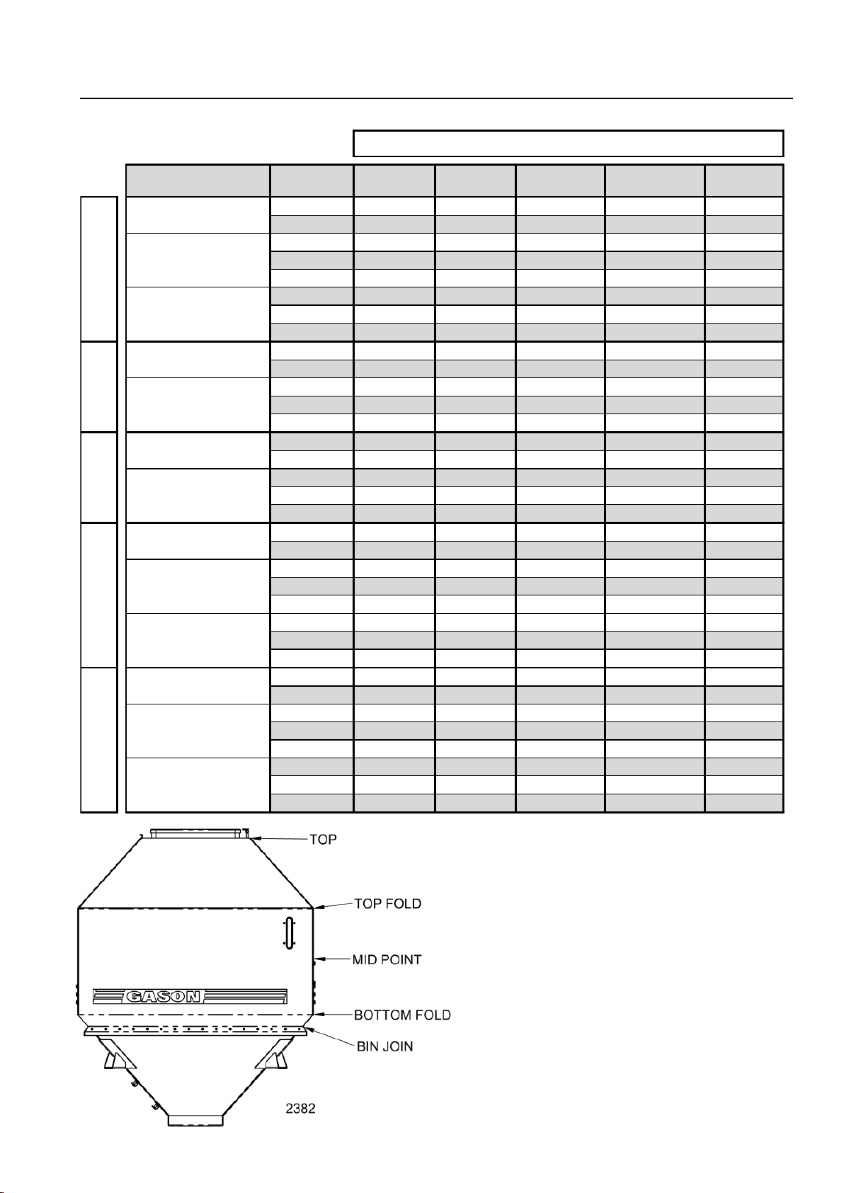
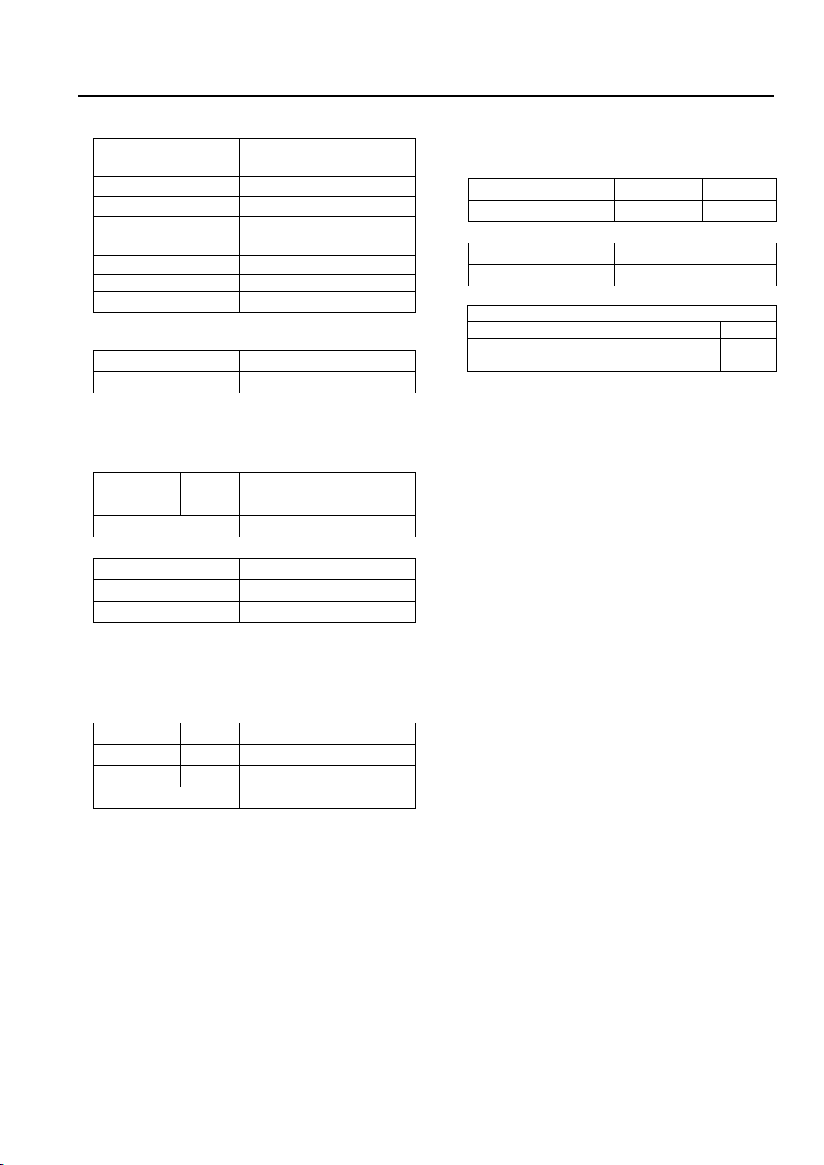
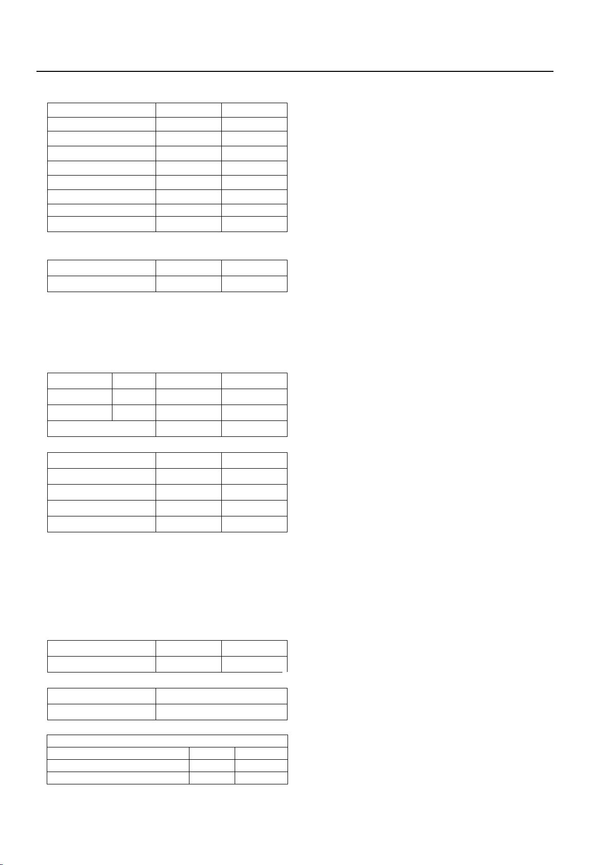
SPECIFICATIONS –LEVEL BIN VOLUME
Page 15
03/12
CONFIGURATION BIN TOP TOP FOLD MID POINT BOTTOM FOLD BIN JOIN
FRONT 2770L 2215L 1456L 700L 535L
REAR 3450L 2783L 1821L 860L 655L
FRONT 2770L 2215L 1456L 700L 535L
MIDDLE 1824L 1404L 923L 442L 340L
REAR 1926L 1506L 1025L 544L 442L
FRONT 2770L 2783L 1456L 700L 535L
MIDDLE 1702L 1282L 862L 442L 340L
REAR 2048L 1628L 1086L 544L 442L
FRONT 3629L 2627L 1848L 890L 517L
REAR 4647L 3410L 2358L 1127L 646L
FRONT 3629L 2627L 1848L 890L 517L
MIDDLE 2099L 1732L 1176L 586L 347L
REAR 27034L 1994L 1335L 692L 450L
FRONT 4064L 3062L 2066L 890L 517L
REAR 5206L 2627L 2638L 1127L 646L
FRONT 4064L 3062L 2066L 890L 517L
MIDDLE 2370L 1842L 1316L 586L 347L
REAR 2987L 2278L 1472L 692L 450L
FRONT 5534L 3766L 2672L 1519L 1005L
REAR 6911L 4744L 3378L 1916L 1263L
FRONT 5534L 3766L 2672L 1519L 1005L
MIDDLE 3177L 2295L 1746L 1049L 719L
REAR 3980L 2695L 1877L 1113L 789L
FRONT 5000L - - - -
MIDDLE 3177L 2295L 1746L 1049L 719L
REAR 3980L 2695L 1877L 1113L 789L
FRONT 6728L 4960L 3287L 1519L 1005L
REAR 8468L 6301L 4156L 1916L 1263L
FRONT 6728L 4960L 3287L 1519L 1005L
MIDDLE 3859L 2984L 2109L 1049L 719L
REAR 4854L 3563L 2293L 1113L 789L
FRONT 5000L - - - -
MIDDLE 3859L 2984L 2109L 1049L 719L
REAR 4854L 3563L 2293L 1113L 789L
2 BIN
3 BIN
(FLAT PANEL)
1+2 BIN (LIQUID)
3 BIN
1+2 BIN (LIQUID)
3 BIN
(DISHED PANEL)
2 BIN
3 BIN
2 BIN
2 BIN
3 BIN
2 BIN
POSITION ON BIN (REFER FIG. BELOW)
3 BIN
1860
1880
1890
2120
2150
Note:
Volumes are for reference only.
Volumes refer to flat water capacity at the
various levels shown. When filling, material
may peak and not flow into rear bin corners.
Volume of 23 L removed from under centre
platform on 2120/50 & 1880/90 to account for
material repose.
Volumes do not include meterbox capacity.

CONVERSION FORMULAE
Page 16
10/09
Useful Conversions –Formulae
LENGTH:
1 km = 0.621371 mile
1 mile = 1.609344 km
1 m = 3.280840 ft.
1 ft = 0.304800 m
1 mm = 0.039390 inch
1 inch = 25.400 mm
SPEED:
1km/h = 0.625 mph
AREA:
1 ha = 10,000 m2= 2.471054 acres
1 acre = 10 sq. chain = 4840 sq. yd. = 0.404685ha = 4840 sq. yd. = 0.404685 ha
1 km2= 0.386102 sq. mile
1 sq. mile = 2.589988 km2
VOLUME:
1 m3 = 35.31476 cu. Ft.
1 cu. ft. = 0.028317 m3
1 L = 0.26418 US gal.
1 US gal. = 3.78531 L
1 UK gal = 1.201 US gal.
1 UK Bushel = 8.00 UK gal. = 1.2843 cu. Ft. = 8.00 U.K. gal. = 1.2843 cu. ft. = 1.2843 cu. ft.
1 L = 0.0274962 UK Bushels
1 UK Bushel = 36.369 L
1 L = 0.0283785 US Bushels
1 US Bushel = 35.2379 L
TORQUE:
1 Nm = 0.7375624 lbft.
1 lbft. = 1.3558175 Nm
FORCE:
1 lbf = 4.4482 N
1N = 0.22481 lbf
PRESSURE:
1 psi = 6.89476 kPa = 0.0689476 Bar
1 kPa = 0.145038 psi = 0.01 Bar
1 Bar = 14.5 psi
MASS:
1 kg = 2.204622 lb
1 lb = 0.453592 kg
1 kg = 1000 grams
POWER:
1 kW = 1.341 hp
1 hp = 745.7 W
DENSITY:
1 kg/m3 = 0.0624 lb/ft3
1 lb/ft3 = 16.0185 kg/m3
APPLICATION RATE:
1 kg/ha = 0.892 lb/acre
1 lb/acre = 1.121 kg/ha
HYDRAULIC HORSE POWER:
1 hp = FLOW (US GPM) x PRESSURE (psi)
1714
MASS FLOW RATE:
kg/min = Application Rate (kg/ha) x Area Rate (ha/hour)
60
lb/min = Application Rate (lb/acre) x Acre Rate (acre/hour)
60
This manual suits for next models
5
Table of contents
Other Gason Seeder manuals


