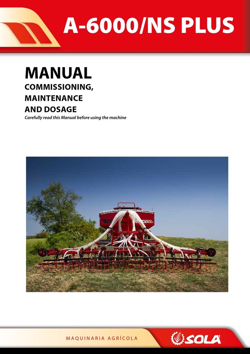
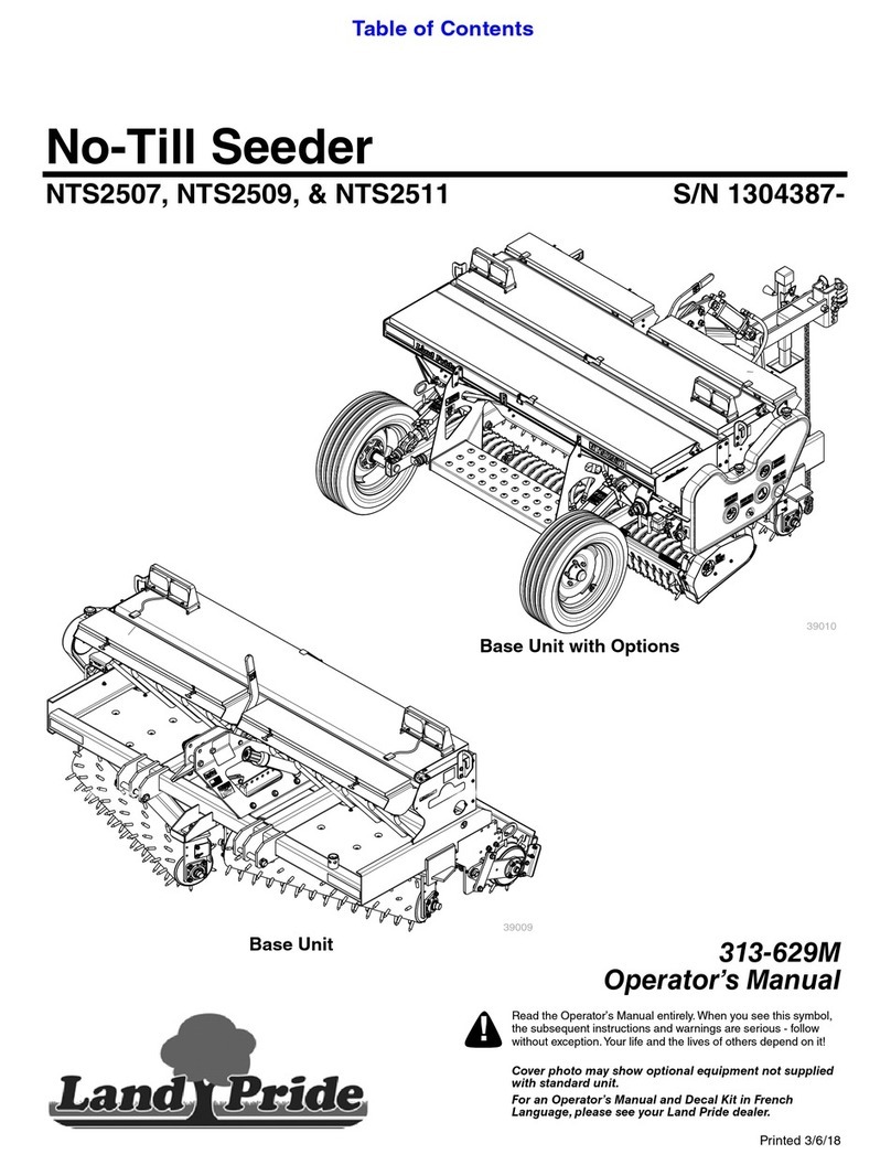
Super Walter W630 User manual

OPERATOR´S MANUAL
W 630

2

3
INDEX
Warranty………………………………….……………………………....Page 05
Introduction……………………………………………………………….Page 07
Safety...…………………………………………………………………...Page 09
Description
Technical specifications of the planter……………………...……………Page 15
Description and calibration of the planter…….…………………….……Page 17
Tractor preparation……………………………………………………….Page 18
Transportation………………………………………….………………….Page19
Hook up of the planter for work………………………………………….Page 19
Planter settings……………………………………………………………Page 24
Planting unit………………………………………………………………Page 27
Variable distance between lines/furrows…………………………………Page 31
Seeding/planting seed distribution…….………………………………….Page 35
Fertilization……………………………………………………………….Page 42
Hydraulic system…………………………………………………………Page 47
Maintenance………………………………………………………………Page 49
Cares during the first days of work……………………………………….Page 50
Tasks at the end of the working season…………………………………..Page 56
Beginning of the working season………………………………………...Page 57
Replacing worn components……………………………………………...Page 58
Trouble-shooting section…………………………………………………Page 61
Transportation laws - special notice……………………………………...Page 63
Special notes……………………………………………………………...Page 65

4

5
Warranty
BUFALO S.A
WARRANTY ON NEW EQUIPMENTS
Bufalo S.A. grants a warranty when selling new products to its dealers in order
to guarantee that these products are free from manufacturing and material
defects.
However, this warranty will be void if the implement is subject to structural
modifications or if the identification plate is eliminated.
Bufalo S.A. will replace any defective piece. Allegedly defective pieces will
have to be shipped for their analysis so as to define whether the piece falls
within the terms of the warranty.
Parts that are subject to natural wear under normal operation conditions are not
included in this warranty and should be replaced from time to time.
WARRANTY CERTIFICATE
Implement Model......................................................................
Serial #.......................................................................................
Implement Delivery Date...........................................................
Farmer.......................................................................................
Address......................................................................................
Telephone.................................................................................
Town..........................................................................................
Dealer’s Signature & Seal

6

7
BUFALO S.A
INTRODUCTION
W630 Planters come from a highly qualified agricultural equipment
manufacturer with many years of experience in the industry.
W630 Planter is durable, dependable, trouble-free equipment designed for
excellent performance under different working conditions with reduced
maintenance.
To achieve maximum equipment performance we recommend first reading this
manual carefully. The Planter is designed and built to last and to bring users
good performance if the instructions contained in this manual are properly
followed. .
In this manual users will find useful information on the W630 options and
calibrations for perfect planting.
The Board

8

9
BUFALO S.A
SAFETY
Safety Messages
All preventive safety warnings included in this manual show this sign. When you
see this sign, please read the messages with attention since they refer to
potential risks derived from handling the planter.
General Precautions
Read this manual before using your planter in order to be better informed about how it
works and therefore, reduce accident risks.
The Planter should be used only by people trained on agriculture equipment handling
and informed about how to operate this product.
Do not allow anyone near your equipment when you are ready to work in the field.
Especially, DO not allow any children near your equipment. Under no circumstances should
children be near agriculture equipment.
Do not introduce any structural modification to your implement without previously
discussing it with your dealer. Any structural modification may affect equipment strength
and/or result in a significant damage with serious economic and / or personal consequences.
Precautions for Road Transport
The equipment you have bought is a pull-type planter; it is designed to be pulled by a
tractor riding at low speed and in daytime. Any other road transport means may jeopardize
yours and other users’ safety and result in accident-related injuries.
Please, transport the implement with empty seed and fertilizer hoppers to prevent
accidents and wear.
Take special care and utmost precautions for planter road-transport. It is advisable to
have one or several sets of rotating warning lights as well as a warning vehicle for further
protection. Remember the planter transport width and consider this is an SMV (Slow Moving
Vehicle) on the road.

10
The implement must be hitched only to the tractor’s drawbar. Hitching the implement to any
other point may result in serious accidents.
Under no circumstances should there be riders in the implement because of the
danger entailed.
Drive safely and slow down before braking or turning. Very large models require
extreme precautions when turning since the implement takes most of any turning room
available. Be aware of instructions contained in the section on how to prepare the planter for
road transport.
The planter must be trailed by a tractor of the same weight or of a weight exceeding
that of the planter. Otherwise, the capacity to stop when operating the brake will be affected.
Constantly verify the maximum height allowed along your road to prevent potential
contact/strikes of your planter with obstacles such as bridges, trees, posts and wires.
Before moving onto the road, check that all your planter safety locks (lift cylinders,
markers, etc.) are in proper position.
Safety chains are required between the planter and the tractor for road transport.
Precautions for Field Operation
Set the parking brake every time you leave your tractor’s driving seat if the planter is
mounted.
Do not operate the hydraulic controls on your planter from anywhere except your
tractor’s driving seat.
Do not park the tractor and planter on slopes.
Before any field operation, check that the planter is properly mounted and that cover
chains, safety locks and other safety protections are in place.
In case you intend to work with seeds or products that may create a toxic cloud, you
are required to wear proper clothing (breathing mask, goggles, gloves) for personal
protection.
11
To connect and disconnect the planter to tractor hydraulic connections, first stop the
tractor engine and release any pressure in the hydraulic system. To release the pressure,
turn on the valve controls in the tractor cab with the engine off.
Precautions for Maintenance
Before servicing the planter with any maintenance job, stop the tractor’s engine, set
the parking brake and set all fixation locks.
Do not service the hydraulic system without releasing the pressure in the circuit first.
Once the service job is complete, be sure that all connections are tight before sending
pressure into the system again.
While servicing the planter for maintenance, protect yourself to prevent any skin
contact with any oil. Any prolonged skin-oil contact will be harmful.
Do not smoke while handling any component that may contain fuel products, e.g., the
oil in the hydraulic system.
When welding or using a torch, try to remove any paint, oil or grease remains and
also remove any nearby hose to prevent fire and toxic gas emission hazards.
Keep your planter clean and in good condition, prevent oil leaks or spills.

12
Safety Signs on your Planter
Figure 1 shows your planter and points where safety signs are. Below you can find an
explanation of each safety sign.
A - Markers Fall
These signs are warnings that state the need
to stay away from the area where the markers
may fall; the goal is to prevent injuries. Figures
2 shows the signs fixed to the markers.
B - Set the safety locks before transporting the planter.
The warning sign (Figure 3) is close to the lift cylinders and
reminds you to set the safety locks before transporting the
CAUTION
1 When starting to work release
the cylinder´s lock pins
2 When transporting the planter
install them back on.
WARNING
DO NOT STAY WHERE
MARKERS MAY FALL
Figure 2
Figure 1
FALLING AREA
Figure 3

13
TRANSPORT WITH
EMPTY HOPPERS
Figure 8
planter. It is very important to set the locks in every transportation movement. To work the
locks must be taken off, to lower the planter.
C - No riders on the implement frame.
Warning (Figure 4) is fixed to the chassis and states the fall risk
of transporting individuals.
D - Set the safety locks.
Before any maintenance or repair job on the seeder, place all
security locks on the hydraulic lift cylinders and fasten the locks
to prevent them from sliding, and wheel chock the planter
unmovable (Figure 5).
E - Maximum transport speed
Maximum transport speed is 25/30 km/hour. A tractor must
transport the implement; tractor weight must exceed seeder
weight (Figure 6).Never transport the planter with another
type of vehicle.
F - Pressure hydraulic hoses.
Oil circulates in the hydraulic hoses under high pressure; in
case of a hose breaking, it may result in serious injuries on
anyone nearby. Discharge pressure before proceeding to any
maintenance job. Do not handle pressurized hoses (Figure 7).
G - Road transport the planter with empty hoppers
In order to prevent potential accidents, breakings or damage
to the planter, when in transport, seed and fertilizer hoppers must be empty (Figure 8).
WARNING
CAUTION
Figure 7
Figure 4
Figure 3
Figure 5
Figure 6

14
H –Place chain covers
Check that the chain covers are set before starting any
work to avoid accidents and protect the planter from
potential impacts or dirt (Figure 9).
The following drawings are fixed to the planter and provide important information relative to
proper operation and maintenance.
I-Re-tighten bolts the first days of work
Important warning fixed on the frame; near the contact drive
wheel, it states how crucial it is to tighten the bolts after the
first few working days, until the setting is stable (Figure 10).
J- Maintenance. Alemites lubrication (grease zerks)
Alemites will be lubricated following instructions relevant to
each case:
A - 10 hours or at the end of every day’s work.(figure 11).
B: 25 hour-interval or every three working days. In case
working days are not very intensive, a one-week interval may
be considered. (Figure 12).
Use grease of high quality (high molibdene content.)
BUFALO S.A.
The following chart shows the main technical characteristics of different W630
planter models.
10 Hs.
25 Hs.
PLACE CHAIN
COVERS
WARNING
Figure 9
Figure 11
Figure 10
Figure 12

15
Features
Planter Model (Lines)
6 - 8
7 - 9
8 - 10
10 - 12
10 - 14
12 - 16
1- Of the Tractor
Minimum power (CV)
70/80
80/90
90/100
90/110
100/120
120/140
Number of hydraulic tractor distributors
1 (optional 2)
Hydraulic System Pressure (kg/cm²)
Minimum 130
2- Of the Planter
Type of seed distribution
Grain per grain. Horizontal seed plate. Pneumatic distribution
Regulation of seed rates
gearbox in oil bath
Number of speeds for seed rating
32 speeds
Working width (in meters)
4,2
4,9/ 4,72
5,60/ 5,25
7/ 6,3
7/ 7,35
8,40
Transportation width (in meters)
Gauge: 3 mts. Total width: 3,40 mts.
Seed hopper capacity (in liters)
Individual hoppers 80
Number of seed lines at 70 cm
6
7
8
10
10
12
Number of seed lines at 52,5 cm
8
9
10
12
14
16
Clearance in transport position
480 mm –to the dented wheel of the covering wheels
Clearance in work position
220 mm –to the edge of the covering wheel
Type of furrow opener
Double disks
Pressure control over the soil
Pressure springs on the planting units - positive or negative pression
Planting depth control
Semi-pneumatic wheels attached to discs
Fertilizer hopper capacity (in liters)
1012
1265
Fertilizer meter type
Chevron system
Fertilizer meter calibration
32 speed Gear box in oil bath
Seed covering elements
Semi pneumatic double wheels, with concave dented discs
Empty planter weight (in kg)
2630/3030
2870/3270
3100/3510
3600/4000
3700/4480
4300/5100
Implement dimensions
In transportation
Length (in meters)
6,4
7,1
7,8
9,2
9,8
10,85
Width (in meters)
3
3
3
3
3
3
Height (in meters)
3,75
3,75
3,15
3,15
3,15
3,15
At work
Length (in meters)
5,4
5,4
5,4
5,4
5,4
5,4
Width (in meters)
4,85
5,55
6,25
7,85
8,2
9,25
Height (in meters)
3,75
3,75
2,9
2,9
2,9
2,9
Transportation wheel tires
11 L 15 or 400/ 60 x 15,5
Contact drive wheel tires
600 x 16”
Accessories & Optional
Only one hopper
Tandem
Other versions

16
Characteristics
Integrated planter models (lines)
12-16
14-18
16-20
20-24
20-26
20-28
24-30
Modules Qty
2
2
2
2
2
2
3
Separation
between lines
(cm)
70/52,5
70/52,5
70/52,5
70/52,5
70/52,5
70/52,5
70/52,5
Working width
(meters)
8,40
9,80
9,45
11,20
10,50
14
12,60
14
13,65
14
14,70
16,80
15,75
Transportation
width (meters)
3
3
3
3
3
3
3
Seed hopper
capacity
960
1280
1120
1440
1280
1600
1600
1920
1600
2080
1920
2240
1920
2400
Fertilization
hopper capacity
2400
2400
2400
3200
3200
4000
3600
Power required
(HP)
120/140
140/150
150/160
160/180
180/210
190/220
220/250
General Information
Double opener discs seed planting
Flat-diameter 406mm (16”) - 3,8mm thickness. Beveled
edge
Opener discs of fertilizer
Flat disc, (16”). 6mm thickness beveled edge
Marker´s discs
Concave, diameter: 406mm (16”) dented
Covering/closing wheels
Concave, diameter: 356mm (14”) dented
No-till disc/coulter blade
Flat- diameter 406mm(16”) - Flutted turbo coulter blades
Planting depth control wheels
Semi-pneumatic wheel 114 x 381 mm (4 ½” x 15”)
Minimum depth: 0, Maximum depth: 11,7cm 19 positions
that advance 6,5mm between them
Covering pressing wheel
Semi-pneumatic wheel 25 x 305 (1” x 12”)
Fertilizer depth registration
Semi-pneumatic wheel, 355 x 76mm minimum depth: 1 cm,
maximum depth 10 cm 9 positions available that increase
10mm from point to point
Distance between lines
70 cm –52,5 cm
DESCRIPTION AND CALIBRATION OF the W630 DV PLANTER
This chapter explains the details of the planter you must know to make the proper
adjustments for proper operation. (Figure 1).

17
4
5
Figure 1
1 Fertilizer hoppers
2Seed hoppers
3 Planting unit
4 Fertilizing unit
5 No-till cultivation discs
6 Opener discs
7 Seed firmer
Figure 2
Tractor preparation
For proper implement use, the tractor must deliver the required power for the drag, wich is
around 8/10 CV for each line at 52,5 cm.
Figure 3
8 Covering- closing wheels
9 Hydraulic markers
10 Contact Drive wheel
11 Planting gearbox
12 Fertilizing gearbox
13 Tow Hitch bar
14 Transportation wheels
15 Step way and Handrail

18
The required power for drag, in normal circumstances, may be inferior as mentioned, but it is
required that the tractors can control the planter in complicated circumstances, such as:
uneven surfaces, humid soils, and transportation in roads, etc.
It is necessary to have enough hydraulic power and liquid flow. The minimum recommended
pressure is of 130 kg/cm2. The planter is designed to work using only one valve from the
tractor. It can be optionally equipped to be operated with two commanding valves, which
allows elevating independently the elevation cylinders and the marker cylinders.
Safety locks location on the planter.
The planter has installed from factory a series of safety locks and devises for various
elements that are described hereafter:
Markers:
In the elevated position its descent can be avoided installing the Locks (A Figure 4) with
their latches in the hydraulic cylinder rods.
Those locking devices must be in place every time the planter is transported and must be
removed before starting to work with the implement.
Respect the security locks of the planter, and use them as recommended and when you
consider it to be convenient. These characteristics are to ensure your safety and for others.
Figure 4
A

19
Transportation hitch bar settings:
In an elevated position, the hitch bar is kept in its place by a butterfly nut A this does not
allow it falling during work (figure 5).
Work hitch bar settings:
While at work, pins A and B keep it in position, (figure 6). For transportation, pin A is
released, that will remain later in the support, and making the hitch bar pivot on pin B in set
against the frame and assured with pin C.
Locks of the lift parallelogram:
The locks fitted in the pins A and B
must be set as indicated in figure 7a,
they set the frame in a lifted position, for
safe transportation.
This allows removing working pressure
and fatigue to the hydraulic system.
During work, these locks are set in a
“resting” position securing them with the
A pin as shown in figure 7b.
Wheel forks, turning locks:
These allow to lock the wheels, during
transportation or working conditions, as
desired pin A (figure 8).
Figure 5
A
A
BC
Figure 6
A
B
A
A
Figure 7a
Figure 8
Figure 7b

20
Hook up of the planter with the tractor. For transport purposes.
The planter you have acquired, has a hitch bar designed for towing purposes through roads
or routes.
To proceed to hook up the planter in transportation position, being in a working position, and
with the working bar still hooked up to the tractor, follow the next steps:
1. Remove the hydraulic cylinder depth stops: A shown in figure 9, if they were installed
in the lifting cylinders that is. Lift totally the planter, and place the locks in the
parallelogram installing the pins A and B shown in figure 7
2. Place the locks: A as shown in figure 4 to the markers in a lifted position, with their
pins and locks.
3. Following, release the pressure of the hydraulic system, and remove the hoses from
the quick coupling of the tractor: A in figure 10.
4. Disconnect from the working hitch of the planter from the tractor, Remove pin A as
shown in figure 6, and turn the hitch bar pivoting on pin B until it reaches the frame,
and lock it against the frame with pin C.
Extreme caution when driving with the planter hooked up, especially in roads, and public
spaces.
Be extremely careful when working and performing any type or regulation in the planter,
first is your safety !!! Avoid accidents.
A
A
Figure 9
Figure 10
Table of contents