Vaderstad Rapid RDA 400S User manual

Original instructions
Instructions
900285-en
27.06.2011
ver. 2
Rapid
series
RDA 400S
Maunfacturing No. 14800-

2 27.06.2011
ver. 2

RDA 400S
3
Table, Tabelle, Tableau
RDA 400-800S No. 14800-
Solrosor
Sunflowers
Sonnen-
blume
0,49
5-20
21-70
Lin
Flax
Fla hs
Lin
0,76
10-60
61-100
Klöver
Clover
Klee
Trèfle
0,77
3-4
5-24
25-40
41-60
Raps
Rape
Raps
Colza
0,65
1,5-3
4-10
11-20
21-30
Gräs
Grass
Gras
Ray-grass
0,36
Kg/ha
2-10
11-20
21-45
-
-
Majs
Maize
Mais
Maïs
0,79
30-100
101-300
301-500
Vi ker
Vet h
Vi ken
Ves es
0,83
30-100
101-300
301-500
Lupiner
Lupins
Lupinen
Luping
0,76
30-100
101-300
301-500
Ärtor
Peas
Erbsen
Pois
0,80
30-100
101-300
301-500
Bönor
Beans
Bohnen
Fèves
0,85
30-100
101-300
301-500
Havre
Oats
Hafer
Avoine
0,50
30-100
101-200
201-350
Korn
Barley
Gerste
Orge
0,67
30-100
101-300
301-500
Råg
Rye
Roggen
Seigle
0,72
30-100
101-300
301-500
Vete
Wheat
Weizen
Blé
0,77
30-100
101-300
301-500
Kg/l
S ale
2
6
15
30
80
140
Se instruktionsbok
See instru tions
Siehe Betriebsanleitung
Voir manuel d’utilisation

4

RDA 400S
27.06.2011
ver.2 5
1 Safety regulations
1.1 Before using the drill ............................................................................ 9
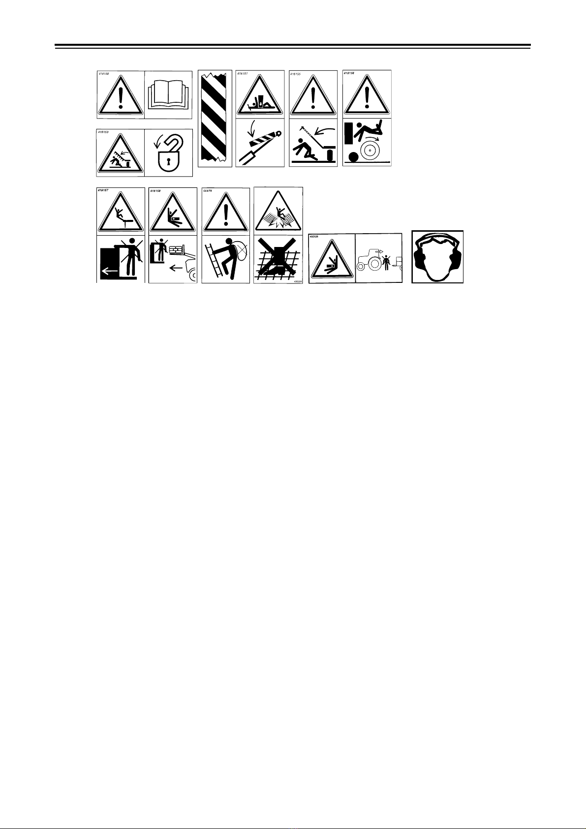
1.2 Warning decals ................................................................................. 10
1.3 Location of warning decals on the achine ........................................... 11
1.4 Other safety precautions .................................................................... 12
1.5 Data plates ....................................................................................... 13
1.6 Moving the achine when not hitched to a tractor ................................. 15
2 Installation instru tions
2.1 Installation of the Control Station on the tractor .................................... 17
3 Instru tions and settings
3.1 Tractor ............................................................................................. 18
3.2 Hitching and unhitching the seed drill without an inter ediate packer ...... 19
3.3 Hitching and unhitching the seed drill with an inter ediate packer ........... 21
3.4 Connecting the hydraulic hoses and electrical cables .............................. 22
3.5 Hose length and hose holder adjust ent .............................................. 24
3.6 Wheel retraction echanis (only achines with the hydraulic depth
adjust ent option) ............................................................................ 25
3.7 Changing between transport position and working position ...................... 26
3.8 Horizontal align ent .......................................................................... 28
3.9 Mechanical adjust ent of sowing depth ................................................ 30
3.10 Hydraulic adjust ent of sowing depth (option 15582-) ........................... 31
3.11 Adjusting the wing sections ................................................................ 34
3.12 Adjusting the changeover valve ........................................................... 35
3.13 Adjust ent of the pre-i ple ents ....................................................... 36
3.14 Adjusting the following harrow ............................................................ 38
3.15 Adjusting Low lift height ..................................................................... 39
3.16 Locking the lifting ra s during service .................................................. 39
3.17 Adjusting the seed coulters ................................................................. 40
3.18 Scraper ............................................................................................ 42
3.19 Bout arker adjust ent ..................................................................... 43
3.20 Track eradicators, tines (option) .......................................................... 43
3.21 Track eradicators, Syste Disc ............................................................ 44
3.22 Wing packers (option) ........................................................................ 44
3.23 Setting the radar ............................................................................... 45
3.24 Adjusting the air-flow ......................................................................... 46
3.25 Seed box setting ............................................................................... 47
3.26 Calibration ........................................................................................ 48
3.27 Prior to filling the hopper .................................................................... 53
3.28 E ptying the seed hopper .................................................................. 54
3.29 Operation test ................................................................................... 55
3.30 Control station .................................................................................. 56
3.31 Interactive Depth Control function, IDC (option 15582-) ......................... 67
3.32 Tra lining ........................................................................................ 71
3.33 Adjusting the pre-e ergence bout arker ............................................ 75
3.34 Hydraulic brakes (accessories) ............................................................ 76
3.35 Maintenance of hydraulic brake syste ................................................ 78
3.36 Pneu atic brakes (accessories) ........................................................... 79
3.37 Maintenance of pneu atic brake syste .............................................. 82

6 27.06.2011
ver. 2
4 Advi e on seeding and driving instru tions
4.1 Sowing depth .................................................................................... 84
4.2 Checking the seed feed ...................................................................... 85
4.3 Sowing headlands ............................................................................. 86
4.4 Engaging the drill .............................................................................. 86
4.5 Inter ediate packer .......................................................................... 87
4.6 Tra lining ........................................................................................ 88
4.7 Bout arkers .................................................................................... 88
4.8 Obstructions ..................................................................................... 88
4.9 Turning with Low lift .......................................................................... 88
5 Maintenan e and servi e
5.1 General aintenance ......................................................................... 92
5.2 Inspecting the drill's towing eyelet ....................................................... 93
5.3 Seed feed housing and rape brush ....................................................... 94
5.4 Locking device .................................................................................. 94
5.5 Cleaning ........................................................................................... 95
5.6 Storing the drill ................................................................................. 96
5.7 Lubrication points .............................................................................. 98
5.8 Service cover .................................................................................. 100
5.9 Changing discs ................................................................................ 100
5.10 Changing disc bearings .................................................................... 101
5.11 Changing seed coulter ounting bolts ................................................ 101
5.12 Changing wheels ............................................................................. 102
5.13 Changing the seals on the hydraulic ra s ........................................... 102
5.14 Changing the valve seals on the lifting ra ......................................... 103
5.15 Repairing and replacing seed hoses .................................................... 104
5.16 Replacing the fan revolution sensor .................................................... 105
5.17 Hydraulic drive trans ission ............................................................. 106
5.18 Replacing the oil filter in the hydraulic unit .......................................... 107
5.19 Inter ediate packer (option) ............................................................ 108
6 Troubleshooting
6.1 General infor ation on troubleshooting .............................................. 109
6.2 Troubleshooting chart ...................................................................... 113
6.3 Alar list ....................................................................................... 119
7 Appendi es
7.1 Sowing table ................................................................................... 122
7.2 Hydraulic diagra ........................................................................... 124
7.3 Electrical syste ............................................................................. 128
7.4 Technical data ................................................................................. 135

RDA 400S
27.06.2011
ver.2 7
INTRODUCTION
Väderstad Rapid A 400 S is a high-capacity cultivation drill. The Rapid drills can be used
under a large variety of conditions, from "direct drilling" to sowing straight after the
plough. This versatility is made possible by the drill's coulter system design and its unique
depth control system, amongst other features.
The machine can be fitted with different types of pre-implements to suit varying farmland
conditions.
IMPORTANT!
This instruction manual is based on experience and results obtained during development of
the Rapid series of drills. Hints and guidelines are to be regarded as general advice, entail-
ing no responsibility whatsoever on the part of Väderstad-Verken AB and/or its represent-
ative. All responsibility for usage, road transport, maintenance and repair etc. of the drill
rests with the owner/driver.
Local conditions affecting crop sequence, soil type, climate etc. may require procedures
different to those mentioned in this manual.
The owner/operator shall bear full responsibility for correct use of the drill at any given
time.
Väderstad drills have passed quality assurance tests and operational tests prior to delivery.
The user/purchaser shall retain sole liability for ensuring that the equipment functions cor-
rectly when in use. In case of complaints, please refer to the “General delivery conditions
of the Väderstad group”.

8 27.06.2011
ver. 2
EC DECLARATION OF CONFORMITY FOR THE MACHINE
in accordance with the EU Machinery Directive 2006/42/EC
Väderstad-Verken AB, P.O. Box 85, SE-590 21 Väderstad, SWEDEN
hereby confirms that the drilling machines hereunder have been manufactured in accord-
ance with the Council Directives 2006/42/EC and 2004/108/EC.
The above declaration covers the following machines:
RDA 400S, manufacturing no. 14800-18000.
Väderstad 2010-06-18
Lars-Erik Axelsson
Legal requirements coordinator
Väderstad-Verken AB
Box 85, 590 221 Väderstad
The undersigned is also authorised to compile technical documentation for the above
machines.

RDA 400S
27.06.2011
ver.2 9
1 Safety regulations
1.1 Before using the drill
Figure 1.1
!Always pay extra attention to paragraphs or figures bearing the following symbol:
!Learn to handle the drill correctly and with care. The drill can be dangerous in inexperienced
or careless hands.

Safety regulations
10 27.06.2011
ver. 2
1.2 Warning de als
Figure 1.2
A
Read the instructions carefully and make sure you understand them.
B
Always make sure that the entire working area and folding area of the seed drill are unobstruct-
ed. Never walk under a suspended section. Always check that the automatic catches have en-
gaged in connection with transport and parking.
C
Warning tape, pay attention to the danger of crushing and impact injuries. Also used on safety
components.
D
Never work under the seed drill without ensuring that the machine is properly supported on
stands or is standing on some other firm surface. Secure the lifting ram and the push rod ram
(1, accessory) by means of the yellow locking device. See also ”3.16 Locking the lifting rams
during service” on page 39.
E
Always ensure that the working area of the bout markers is unobstructed. Bear in mind the dan-
ger of injury when folding or unforlding the bout markers or getting caught between the seed
drill and the bout markers when they are folded in.
NOTE!
The bout markers are always folded
in when the machine is raised, regardless of the indication on the control box. The marker arm
will always fold as the machine is lowered. Therefor always shut off the control box main
switch when the machine is not on the field. All settings will remain unchanged though the box
is shut off.
If the machine is parked and left resting only on the wheels and support leg, the bout markers
could start to slowly unfold due to internal overleakage in the hydraulic system. Make it a habit
to always park the machine on its wheels, discs and support leg and always block the bout
markers with the safety cotter pins.
F
Do not climb onto the wheels when the seed drill is parked as they can rotate.
G
Do not stand on the seed drill while it is in use.
H
Do not stand on the seed drill during front loading of seed.
I
The ladder and platform of the drill are not designed for manual loading from small seed bags.
J
Do not stand on the upper grating of the seed hopper.
K
Do not stand between the tractor and the machine when reversing the tractor to hitch the drill.
L
Use ear defenders when adjacent to the running fan.
A
C D
B
H
E F
GJI KL

RDA 400S
27.06.2011
ver.2 11
1.3 Lo ation of warning de als on the ma hine
Figure 1.3
J
E
D
C
F
G,H,I,K
A,B,D,L

Safety regulations
12 27.06.2011
ver. 2
1.4 Other safety pre autions
!Observe the greatest caution when transporting the seed drill on a public road. If the machine
has a full hopper, note that the towed weight is considerable and that the view to the rear is
greatly restricted. Check the adjustment of the tractor's rear-view mirrors. If the machine is to
be transported over a longer distance, be sure to block the lifting ram of the centre section with
the yellow mechanical locking device, see ”3.16 Locking the lifting rams during service” on
page 39. The owner/operator is solely responsible for transport of the seed drill on public
roads. Use the lights on the drill according to the local traffic regulations.
!
NOTE!
This machine/equipment together with its tyres is designed for a maximum speed of
30 km/h, during transportation on the road.
!Make sure that at least 20% of the tractor's weight is resting on its front wheels when the drill
has been hitched and loaded. This will ensure full steering ability of the tractor train.
!When any repair work is carried out on the hydraulic system, the seed drill should be in the
lowered position and resting on a firm and level surface with the wing sections lowered!
!Never stand under the intermediate packer or drill if it is suspended and only secured with the
tractor's hydraulic lifting arms. Prior to any service on the intermediate packer, be sure to se-
cure it properly with trestles, etc. on firm, level ground.
!Be sure to set the master cylinder stopper in such a way that the drill rests on both the wheels
and the discs when parked. Since the weight on the supporting leg is so high, the machine shall
not be parked on loose surface!
!Always make sure that the seed drill's male couplings and the tractor's female couplings are
clean and free from impurities before connecting them together.
!Always use genuine Väderstad spare parts to maintain the quality and reliability of the seed
drill. If other brands of spare parts are used, all guarantee and claim commitments cease to be
valid.
!Regularly inspect the wear on the drill's towing eyelet. Replace the towing eyelet when it has
been worn down to the wear limit. See ”5.2 Inspecting the drill's towing eyelet” on page 93.
!Any welding work on the machine/implement should hold professional standard.
Incorrect welding may result in serious injuries or possibly fatal injuries. If in doubt, contact a
professional welding service for proper instructions.
!Never look straight into the optics of the radar when it is operating! There is a risk of permanent
damage to the eyesight! (Hydraulic feed output).
!When cleaning the drilling system or when servicing the transmission system on machines
with hydraulic feed output, the hydraulic flow to the fan and feed output driving mechanism
must always be shut off beforehand.

RDA 400S
27.06.2011
ver.2 13
1.5 Data plates
!The machine is equipped with either a combination of signs 1.5.1, Serial number plate, and
1.5.2, CE plate, or 1.5.3, Machine label.
1.5.1 Serial number plate
Figure 1.4
A
Type number
B
Manufacturing number. Always state the manufacturer number for your machine when order-
ing spare parts and in case of warranty claims.
1.5.2 CE plate
Figure 1.5
C
Working width
D
Transport width
E
Serial (CE) number
F
Weight, total weight fully equipped and with maximum load. For more information, see ”7.4
Technical data” on page 135.
G
Year of manufacture
AB
CE F G
D

Safety regulations
14 27.06.2011
ver. 2
1.5.3 Ma hine label
Figure 1.6
A
Machine type
B
Manufacturing serial number
(Always state the serial number of your machine when ordering spare parts and in case of serv-
icing or warranty claims.)
C
Year of manufacture
D
Working width
E
Transport width
F
Tare weight of the basic machine
G
Maximum total weight
H
Maximum permitted payload
I
Maximum permitted axle loading
J
Maximum coupling load (at the tractor hitch)
!Also refer to ”7.4 Technical data” on page 135.
A
B
D
EI
J
G
C
F
H

RDA 400S
27.06.2011
ver.2 15
1.6 Moving the ma hine when not hit hed to a tra tor
NOTE!
If the machine must be moved when not hitched to a tractor,it must be transported on a ma-
chine trailer or lorry flatbed!
The machine must be rolled onto and off the transport vehicle using a tractor. Lifting with a crane
is prohibited!
1 Set the machine to the transport position; see ”3.7.2 Changing to transport position” on page
27.
2 Activate the wheel retraction function (Only applies to machines with hydraulic depth setting),
see ”3.6 Wheel retraction mechanism (only machines with the hydraulic depth adjustment
option)” on page 25.
3 Raise the pre-implement to the full lifting height.
4 Reverse the machine lengthwise onto the trailer or flatbed. If using a flatbed, a ramp, loading
pier or similar will be required. Take great care. Check that no machine parts are damaged
during loading.
5 Lower the machine. Adjust the master cylinder's stop device and parking stay so that the
machine rests on the wheels, discs and support (or intermediate packer) in the lowered position.
Make sure that the machine's hydraulic system is depressurised.
6 Secure the machine's transport wheels to prevent rolling using chocks or similar.
7 Secure the tarpaulin using tension straps or similar.
8 Unhitch the tractor from the machine.
9 Secure the machine using suitable lashing equipment in accordance with applicable rules. The
lashing equipment must be attached to the machine at the locations indicated by the decals; see
“Figure 1.7”.
!For information on the machine's dimensions and weight, see ”7.4 Technical data” on page
135!
!Always make sure that you comply with applicable national regulations concerning transport
dimensions, requirements for escort vehicles or similar!
Figure 1.7

Safety regulations
16 27.06.2011
ver. 2

RDA 400S
27.06.2011
ver.2 17
2 Installation instru tions
2.1 Installation of the Control Station on the tra tor
1 Be sure to install the control box securely in the tractor cab. Place the control box within the
field of vision while looking in the travelling direction. Install the bracket as shown in the il-
lustration.
NOTE!
Check for hidden cables before drilling holes in the tractor cab.
2 Connect the Control Station to the electrical socket on the tractor. If an electrical power outlet
is not available, extra wiring must be installed. Preferably use 6 mm² cable. Connect the cables:
Brown to positive (+) and blue to earth (-).
NOTE!
The polarity must not be reversed.
It is important to have good wiring connections, as a loose connection will prevent correct opera-
tion.
Do not use a cigarette lighter outlet,as the current consumption is up to 20 A.
Make sure that the connecting cable to the drill is not trapped under the rear window of the tractor
as this may cause damage. Use a hatch or a hole. Securely clamp the cable in the tractor cab. This
protects the Control Station from damage in case the connection cable has inadvertently not been
disconnected prior to unhitching the drill.
Figure 2.1 Figure 2.2

Instru tions and settings
18 27.06.2011
ver. 2
3 Instru tions and settings
NOTE!
All basic adjustments must be carried out with the Rapid drill on a level surface, with the
wing sections lowered and with the drill hitched to a tractor.
3.1 Tra tor
3.1.1 Tyre equipment and weights
To reduce soil compaction and to increase the pull, the tractor should be fitted with very good
tyres.Try to have as low tyre pressure as possible. Any front weights on the tractor should be re-
moved.
3.1.2 Tra tor hydrauli system requirements
1 pressure-free return input, 3/4”, for return oil from the fans. Contact your tractor distributor for
instructions on how this is to be installed.
4 x double-acting hydraulic couplings, 1/2", with the following functions:
A
For fan operation one double-acting hydraulic coupling is required, with a capacity of 40 l/min.
at 180 Bar. This coupling requires an individually adjustable flow.
B
For the raising/lowering of the seed drills and to operate the bout markers, one double-acting
hydraulic coupling is required, with a capacity of 40 l/min. at 180 bar.
NOTE!
It must be possible to use the hydraulic couplings mentioned in A and B above simultane-
ously.
C
For the retraction and extension functions and for operating the Crossboard, one double-acting
hydraulic coupling is required, with a capacity of 20 l/min. at 180 bar.
D
For the raising/lowering of pre-implements, one double-acting hydraulic coupling is required,
with a capacity of 20 l/min. at 180 bar.
Figure 3.1 Figure 3.2

RDA 400S
27.06.2011
ver.2 19
3.2 Hit hing and unhit hing the seed drill without an inter-
mediate pa ker
3.2.1 Hit hing
Figure 3.3
1 Connect the drill to the tractor hitch device.
2 Raise and secure the machine parking stay.
3 Fold the hose holder forward and connect the hydraulic hoses and electrical cabling, see also
”3.4 Connecting the hydraulic hoses and electrical cables” on page 22.
4 Check that the hoses and cables are hanging free, even during sharp turns, see also ”3.5 Hose
length and hose holder adjustment” on page 24.
!Regularly inspect the tractor's hitch device and the drawbar eye on the implement for wear, see
”5.2 Inspecting the drill's towing eyelet” on page 93.

Instru tions and settings
20 27.06.2011
ver. 2
3.2.2 Unhit hing
Figure 3.4
!Unhitching and parking must always take place on a level and solid surface.
1 Lower and secure the machine parking support.
2 Be sure to adjust the master ram stopper and the parking stay in such a way that the drill rests
on the wheels, discs and its stay when parked. Since the load on the stay is very high, avoid
parking the drill on soft ground.
3 Disconnect the drill from the tractor hitch.
4 Disconnect the hydraulic hoses and electrical cables. Fold back and secure the hose holders in
the upright position.
Figure 3.5
NOTE!
If the machine is parked and left resting only on the wheels and parking stay, the bout
markers could start to slowly unfold due to internal overleakage in the hydraulic system. Make it
a habit to always park the machine on its wheels, discs and stay and always block the bout markers
with the safety cotter pins.
NOTE!
If the seed drill is to be parked with a full seed hopper, or in a location where the ground
conditions may not be fit to carry the load, a plank or similar must be placed under the parking
stay foot to spread the load.
Other manuals for Rapid RDA 400S
1
This manual suits for next models
2
Table of contents
Other Vaderstad Seeder manuals
Popular Seeder manuals by other brands

Toro
Toro 23510 Operator's manual

John Shearer
John Shearer Pasture Renovation Drill Operator's manual

Brillion
Brillion TURFMAKER Junior SLP2041 Operator's manual

Sulky
Sulky CULTLINE VR 300 Series Original instructions

Landoll
Landoll Brillion SS16 Operator's manual

Amazone
Amazone Centaya 3000 Special Original operating manual