Gast 120R User manual

Part No. 6190761 (Rev A)
120R-40M, 120R-40MQ3
2x120R-40MQ6, 2x120R-40M
6190761 | REV A
® Registered Trademark/™ Trademark of JUN-AIR Inc. ©Copyright 2022 JUN-AIR Manufacturing Inc. All Rights Reserved.
WWW
.
JUN
-
AIR
.
COM
ISO 9001 CERTIFIED
A BRAND OF
®
Compressor
A BRAND OF
®

2
6190761 (Rev A) 120R Basic Compressor User Guide
© 2022, JUN-AIR
We reserve the right to make any alterations which may be due to any technical improvements
Printed in the USA
Table of Contents
DB Operating Manual ................................................................................................. 5
DE Betriebsanweisung ............................................................................................... 5
FR Mode d’emploi .................................................................................................... 5
ES Modo de empleo................................................................................................... 5
NL Gebruiksaanwijzing ................................................................................................ 5
DK Betjeningsforskrift ................................................................................................ 5
Technical specifications
Technische Daten
Caracteristiques techniques
Detalles téchnicos
Technische gegevens
Tekniske specifikationer
Diagrams
Zeichnungen
Dessins
Diagramas
Tekeningen
Diagrammer
Spare parts
Ersatzteile
Pieces detachées
Piezas de recambio
Onderdelenlijst
Reservedele
Symbols
Abbildungen
Symboler

3
© 2022, JUN-AIR
We reserve the right to make any alterations which may be due to any technical improvements
Printed in the USA
120 Basic Compressor User Guide 6190761 (Rev A)
Warranty
Provided that the instructions for operation, maintenance and
service have been carried out, your JUN-AIR compressor is
guaranteed against faulty material or workmanship for 2 years.
The air receiver is guaranteed for 5 years.
The guarantee does not cover damage caused by violence,
misuse, incorrect repairs or use of unoriginal spare parts. Costs
of transportation of parts/equipment are not covered by the
guarantee.
JUN-AIR’s Conditions for Sale and Delivery will generally apply.
JUN-AIR International A/S reserves the right to change technical
specifications/constructions.
DE – Garantie
Vorausgesetzt, dass die Anweisungen für Betrieb und
Wartungerfüllt sind, gewährt JUN-AIR 2 Jahre Garantie bei
Materialoder Fertigungsfehlern.
Auf den Druckbehälter gewährt JUN-AIR 5 Jahre Garantie.
Ausgenommen von Garantieleistungen sind Schäden die durch
Gewalt, falsche Bedienung, nicht fachgerechte Reparaturen oder
durch Verwendung nicht originaler Ersatzteile verursacht wurden.
Transportkosten sind von der Garantie ausgeschlossen.
Es gelten die allgemeinen Geschäfts- und Lieferbedingungen von
JUN-AIR.
JUN-AIR behält sich das Recht von technischen Änderungen vor.
DK – Garanti
Under forudsætning af at alle betjenings- og serviceforskrifter
overholdes, ydes der 2 års garanti for alle materiale- og
fabrikationsfejl.
Dog ydes der 5 års garanti for beholdergennemtæring.
Garantien omfatter ikke skader, som skyldes vold, misbrug,
fejlagtige reparationer eller uoriginale reservedele.
Transportomkostninger er ikke omfattet af garantien.
For Skandinavien gælder i øvrigt NL 92 Salgs- og
Leveringsbetingelser.
JUN-AIR International A/S forbeholder sig retten til ændringer i
tekniske specifikationer og konstruktion.

4
6190761 (Rev A) 120R Basic Compressor User Guide
© 2022, JUN-AIR
We reserve the right to make any alterations which may be due to any technical improvements
Printed in the USA
SAFETY
Important - read this first!
Please read the following information and operating instructions
included with this product before use. This information is for your
safety and it is important that you follow these instructions. It will
also help prevent damage to the product. Failure to operate the unit
in accordance with the instructions or using JUN-AIR unauthorized
spare parts can cause damage to the unit and could cause serious
injury.
IMPORTANT: General instructions for installation
• If the compressor is not fitted with a supply plug, a circuit
breaker must be incorporated in the fixed wiring.
• If this unit is supplied with a three-pin plug, connect with a
properly earthed outlet only.
CAUTION: To reduce risk of electric shock
• Only authorized service agents should carry out service.
Removing parts or attempting repairs can create an electric
shock. Refer all servicing to qualified service agents.
WARNING: To reduce risk of electrocution
• Do not use this unit with electrical voltages other than stated
on the rating plate.
• Always unplug this unit immediately after use and store in a dry
place.
• Do not use this product in or near liquid or where it can fall or
be pulled into water or other liquids.
• Do not reach for this product if it has fallen into liquid. Unplug
immediately.
• This unit is not weatherproof. Never operate outdoors in the
rain or in a wet area.
DANGER: To reduce risk of explosion or fire
• During spraying with combustible liquids, risk of explosion may
arise, particularly in closed rooms.
• Do not use this product in or near explosive atmospheres or
where aerosol products are being used.
• Do not pump any other gases other than atmospheric air.
• Do not pump combustible liquids or vapours with this product;
do not use it in or near areas with combustible or explosive
liquids or vapours.
• Do not use this unit near open flames.
CAUTION: To prevent injury
• Compressed air can be dangerous; do not direct airflow at
a person’s head or body.
• Always keep the system out of reach of children.
• Never operate this product if it has a damaged power lead or
plug, if it has been dropped or damaged, or if it has fallen into
water. Return the product to a service center for examination
and repair.
• Keep the electrical cable away from hot surfaces.
• Ensure all openings are kept free of restriction, and never
place the motor on a soft surface where the openings may
be blocked. Keep all openings free from dust, dirt and other
particles.
• Never leave this product unattended when plugged in.
• Never insert fingers or any other objects into fans.
• This unit is thermally protected and can automatically restart
when the overload resets.
• Wear safety glasses, when servicing this product.
• Use only in well ventilated areas.
• This product may only be connected to units or tools with a
max. pressure rating higher or equal to that of the compressor.
• The surface of the compressor can get hot. Do not touch
compressor motor during operation.
Failure to observe the safety precautions could result in severe
bodily injury, including death in extreme cases.
IMPORTANT: General directions for use
• Protect compressor against rain, moisture, frost and dust.
• The compressor is constructed and approved for a max.
pressure as stated under Technical Specifications.
• Do not operate the compressor at ambient temperatures
exceeding 40°C/104°F or falling below 0°C/32°F.
• If the supply power lead on the compressor is defective, an
authorized Jun-Air distributor or other qualified personnel
must carry out the repair.

5
© 2022, JUN-AIR
We reserve the right to make any alterations which may be due to any technical improvements
Printed in the USA
120 Basic Compressor User Guide 6190761 (Rev A)
INSTALLATION
Your JUN-AIR compressor is easy to operate. Observe the
instructions and you will get many years service from your
compressor.
• Visually inspect unit for shipping damage, contact your supplier
immediately if you think the unit may have been damaged.
• Check that the performance of the compressor matches the
actual air consumption, please refer to Technical Specifications.
• Check that the rating plate of the compressor corresponds with
the electrical voltage offered and check that fusing is adequate.
Placing
Place the compressor in a dust-free, dry and cool, yet frost-free room.
Sufficient cooling from the surroundings is important.
• Ambient temperature: 0°C to 40°C, 32°F to 104°F
• Relative humidity: Max 90%
Mount the two distance bolts (1) on the back of the cabinet to ensure
sufficient ventilation.
Installation
• Mount the drain bottle (2) visibly outside the cabinet and mount
the hose at the back of the cabinet (3).
• Connect the cable at the back of the cabinet (5).
• Plug the compressor into a standard outlet switch.
• Connect equipment at the back of the cabinet (4).
• The front wheels are delivered with brakes. Brake the wheels
before starting the compressor (6).
Thermo Switch
The fans are controlled by a Stego thermo switch adjusted to 30°C
from the factory – do not alter this setting. Check that the setting is
correct and adjust if necessary.
The fans will start when the temperature inside the cabinet exceeds
30°C and will run continuously until the temperature drops below
30°C.

6
6190761 (Rev A) 120R Basic Compressor User Guide
© 2022, JUN-AIR
We reserve the right to make any alterations which may be due to any technical improvements
Printed in the USA
OPERATION
• If the compressor has been stored at an extremely low
temperature, allow it to heat to room temperature before
switching it on.
• The cut-in and cut-out pressure is preset from the factory and
it is normally not necessary to change this. However, if it is
necessary to change the preset settings, the instructions of this
manual shall be followed carefully.
• All AC compressors are designed for 100% duty, but 50%
operation is recommended to prolong the lifetime.
• The fans on the back of the cabinet will start when the
temperature exceeds 30°C. It will run continuously even if the
compressor may have switched of until the temperature is below
30°C again.
• Do not lubricate the oil-less motor with oil, as it will destroy
important components.
Start
Start the compressor by pressing the green button.
The green lamp for compressor in operation is now
alight.
Read the outlet pressure on the pressure gauge.
Adjust the pressure on the regulator.
Read the receiver pressure on the pressure gauge.
The green lamp is alight when the fans are in operation.
Read on the hour counter the elapsed service time.
If the compressor does not start, there might be pressure in
the receiver. The compressor will automatically start when the
pressure drops.
The compressor will automatically stop when the preset cut-out
pressure is reached.
Stop
Turn off the compressor by pushing the green button.
The green light for compressor in operation switches off.

7
© 2022, JUN-AIR
We reserve the right to make any alterations which may be due to any technical improvements
Printed in the USA
120 Basic Compressor User Guide 6190761 (Rev A)
MAINTENANCE
To ensure a long lifetime of the compressor, it is important that
inspection and maintenance is carried out regularly as described in
the following.
Read the elapsed operation time on the hour counter.
Opening of cabinet
Turn the four () locks clockwise with a screwdriver or sim. to
open the cabinet.
Preventive maintenance
Activity Weekly Monthly
One a year,
or every
2000 hours
aDrain condensate •
bCheck filter regulator •
cCheck for leaks •
dClean the unit •
eCheck safety valve •
fCheck inlet filter •
gCheck non-return
valve •
hCheck fans •
iCheck dryer •
a) Drain condensate
If drain bottle is installed, empty when necessary. ().
b) Check outlet filter
Check and change the filter and filter element in accordance with
the instructions in ”Installation and maintenance instructions” for
the filter in question.
c) Check for leaks
Check motor, hoses and equipment for leaks. Check the pumping
time.
d) Clean the unit
Clean the unit when needed with a soft, damp cloth. If necessary,
use paraffin to remove adhesions. Dust and dirt prevent cooling.
e) Check safety valve
Check the safety valve with pressure in the receiver. The safety valve
is operated by pulling the ring (1) or turning the screw (2) depending
on the valve type.
f) Check intake filter
Check the intake filter and change it if necessary.
g) Check the non-return valve
Turn off the compressor on the mains switch and pull out the
plug.
Empty the receiver for compressed air by operating the safety
valve. When the receiver is empty, the reading of the pressure
gauge is bar.
Dismount the non-return valve from the receiver.

8
6190761 (Rev A) 120R Basic Compressor User Guide
© 2022, JUN-AIR
We reserve the right to make any alterations which may be due to any technical improvements
Printed in the USA
Disassemble the non-return valve and remove the O-ring () part
no. from the piston.
Clean the non-return valve.
Mount a new O-ring and re-assemble the non-return valve.
Re-install the non-return valve.
h) Check the fans
Check that the fans at the back of the cabinet work. They
will start when the temperature exceeds °C and will run
continuously until the temperature falls below °C.
i) Check dryer
If a dryer is installed refer to the operating manual for the dryer.
Please note that all service must be carried out by a qualified
person.
Adjustment of pressure switch
The working presure has ben preset from the factory, and it is
normally not necessary to change this.
However, if it is necessary to change the preset settings, the
instructions mentioned below should be followed carefully.
Warning
The compressor is constructed and approved for a max.
pressure as stated under Technical Specifications - do not
adjust to a higher pressure.
Higher working pressure will reduce the lifetime of the
compressor.
The compressor will stop at max. pressure (stop pressure) and
start again at min. pressure (start pressure). The difference
between max. and min. pressure is the differens pressure.
Unscrew the lid of the pressure switch. Adjust max. pressure
adjusting the two springs marked A (clockwise: higher pressure).
Adjust the two springs identically.
Adjust the differens pressure adjusting the spring marked B
(clockwise: higher differens pressure, start pressure maintained).
Test of pumping time
The pumping time indicates the condition of the compressor.
. Check that there are no leaks in the system.
. Empty the air receiver of compressed air so that the
pressure gauge shows bar.
. Close the filter regulator and check that the drain valve is
closed.
. Start the compressor and note the time it takes until it is
turned off again by the pressure switch. Check that the
pumping time agrees with the technical specifications for
the actual compressor system.
Please note that the pumping time in this manual is given for to
max pressure. Deviations from this result in deviating results.
Important
Always test the pumping time when cold. If the compressor is
warm, the pumping time will be considerably longer.
FAULT FINDING AND REPAIR
Important
Switch off and isolate from electrical supply before removing
any parts from the pump. Empty air receiver of air before
performing any operation on the compressors’ pressure
system.
1. Compressor does not start
a. The air receiver is pressurized. The motor will start when
the pressure has dropped to the preset start pressure.
Empty the receiver.
b. Check that the mains supply agrees with the motor
label.
c. No power from mains. Check fuses and plug.
d. Bad connection or broken cable.
e. The motor is overheated and the thermal protection
has switched it off. When cooled the motor will turn on
automatically. Go to section .
f. The compressor has not been unloaded and there
is back pressure on the piston. Ensure that the
compressor is unloaded each time it stops.
g. The motor is blocked.
h. Defective capacitor.
2. The compressor makes a buzzing sound but does not start
a. Leaky non-return valve. Dismount the pressure pipe and
check if air leaks from the non-return valve. Clean and
replace.
b. The motor is blocked.

9
© 2022, JUN-AIR
We reserve the right to make any alterations which may be due to any technical improvements
Printed in the USA
120 Basic Compressor User Guide 6190761 (Rev A)
3. The compressor runs but the pressure does not increase
a. Intake filter clogged. Replace.
b. Non-return valve is clocked. Clean or replace.
c. Leaks in fittings, tubes or pneumatic equipment. Check
with soapy water or by letting unit stay over night
disconnected from mains. Pressure drop should not
exceed bar.
d. Check the piston gaskets. Replace if necessary.
e. Defective valve plate. Contact your JUN-AIR distributor.
4. The motor gets very hot
a. The ambient temperature is too high. If the motor is
installed in a cabinet, sufficient ventilation must be
ensured.
b. Leaks in fittings, tubes or pneumatic equipment. Check
with soapy water or by letting unit stay over night
disconnected from mains. Pressure drop should not
exceed bar.
c. The compressor is overloaded.
5. The compressor runs even if no air is tapped
a. Leaks in fittings, tubes or pneumatic equipment. Check
with soapy water or by letting unit stay over night
disconnected from mains. Pressure drop should not
exceed bar.
6. The compressor does not start at min pressure or does not
stop at max pressure.
a. Defective pressure switch. Replace.
PRESSURE VESSEL
Pressure tested at 4-25 litre 24 bar
40-50 litre 18.3 bar
Directions for use
Application Receiver for compressed air
Receiver specifications See name plate
Installation Tubes, etc. must be installed with
suitable materials
Placement
Observe the working temperature of
the receiver
Ensure sufficient room for
inspection and maintenance
The receiver must be kept in a
horizontal position
Corrosion protection
The surface treatment must be
maintained as required
Internal inspection at least every
five years
Drain condensate at least once a
week
Alternation/repair No welding must be made on
pressurized parts
Safety valve
Ensures that PS will not be
exceeded
Never adjust to a higher pressure
than PS
The capacity of the valve must
be calculated in accordance with
teh volume of air supplied by the
compressor
PS - Maximum working pressure of
the receiver

10
6190761 (Rev A) 120R Basic Compressor User Guide
© 2022, JUN-AIR
We reserve the right to make any alterations which may be due to any technical improvements
Printed in the USA
Technical Data & Specifications
Specifications 120R-40M 120R-40MQ3 2x120R-40M 2x120R-40MQ6
Tank size liter 40 40 40 40
U.S. gallon 10.6 10.6 10.6 10.6
Weight kg 111 116 152 169
lbs 245 256 335 373
Dimensions
(LxWxH)****
mm 720 x 650 x 860 720 x 780 x 860
in 28.0 x 25.5 x 34.0 28.0 x 30.5 x 34.0
Pumping time @ 50 Hz 90 sec. 96 sec. 52 sec. 80 sec.
@ 60 Hz 78 sec. 88 sec. 45 sec. 65 sec.
Noise level @
1 m
@ 50 Hz 66 dB(a) 66 dB(a) 69 dB(a) 69 dB(a)
@ 60 Hz 69 dB(a) 69 dB(a) 72 dB(a) 72 dB(a)
Technical modifications reserved.

11
© 2022, JUN-AIR
We reserve the right to make any alterations which may be due to any technical improvements
Printed in the USA
120 Basic Compressor User Guide 6190761 (Rev A)
English German French Spanish Dutch Dansk
Voltage Spannung Voltage Voltaje Voltage Spænding
Frequency Frequenz Fréquence Frequencia Frequentie Frekvens
Power Motor HP Moteur CV Motor CV Motor HP Effekt
Displacement Ansaugleistung Débit Aire aspirado Capaciteit Ydelse
Max. pressure Max. Druck Pression de service
max.
Presión de régimen
máx.
Max. druk Max. driftstryk
Max. current Stromverbrauch Consommation Corriente máxima Max. stroom Strømforbrug
Tank size Behältervolumen Volume réservoir Volumen de tanque Tankvolume Beholderstørrelse
Weight Gewicht Poids Peso Gewicht Vægt
Dimensions
(l x w x h)
Abmessungen
(l x b x h)
Dimensions
(l x p x h)
Dimensiones
(l x a x h)
Afmetingen
(l x w x h)
Dimensioner
(l x b x h)
Noise level Schallemissionen Niveau sonore Nivel de ruido Geluidsniveau Lydniveau
Pumping time Pumpzeit Temps de refoule-
ment
Tiempo de bombeo Pomptijd Oppumpningstid
Neutral is required Null-leiter ist er-
forderlich
Neutre nécessaire Neutro necesairo Neutraal noodza-
kelijk
Nul-leder kræves
Available for opera-
tion at a maximum
pressure of 10
barg/145 psig upon
request. Please
note that operation
at higher pressure
will influence the
life time.
Auf Anfrage er-
hältlich bis zu einem
Betriebsdruck
von max. 10 bar.
Höherer Druck hat
Auswirkungen auf
die Lebensdauer.
Kan leveres til max.
driftstryk på 10 bar.
Bemærk at øget
driftstryk reducerer
levetiden.
Displacement is
reduced by approx.
18-20% on units
with dryer (D).
Min. pressure
required to operate
dryer: 6 bar.
Bei Kompressoren
mit Adsorption-
strockner reduziert
sich die effektive
Luftliefermenge um
18-20% (D). Mind-
estarbeitsdruck für
den Lufttrockner
beträgt 6 bar
Le débit est réduit
de 18-20% pour les
unités avec sécheur
d’air (D) Pression
min. 6 bar
Le capacidad se
reduce con 18-20%
para las unidades
con secador de aire
(D)
Bij systemen
met droger is de
capaciteit ca. 18-
20% lager (D). Min.
benodigde druk
voor de droger: 6
bar
Ydelsen reduceres
med ca. 18-20% på
kompressorer med
tørrer (D). Min. tryk
til drift af tørrer: 6
bar
3-phase units are
approx. 100 mm
wider than 1-phase
units
3 phasige Anlagen
ca. 100 mm breiter.
3-fasede anlæg er
ca. 100 mm bredere
end 1-fasede anlæg.
Technical modifica-
tions reserved.
Technische Änder-
ungen vorbehalten
Droits réservés
pour modifications
techniques
Reservamos el
derecho a cambiar
estas especifica-
ciones técnicas sin
previo aviso
Technische wijzigin-
gen voorbehouden
Ret til ændringer
forbeholdes
Translations

12
6190761 (Rev A) 120R Basic Compressor User Guide
© 2022, JUN-AIR
We reserve the right to make any alterations which may be due to any technical improvements
Printed in the USA
Performance Curves

13
© 2022, JUN-AIR
We reserve the right to make any alterations which may be due to any technical improvements
Printed in the USA
120 Basic Compressor User Guide 6190761 (Rev A)
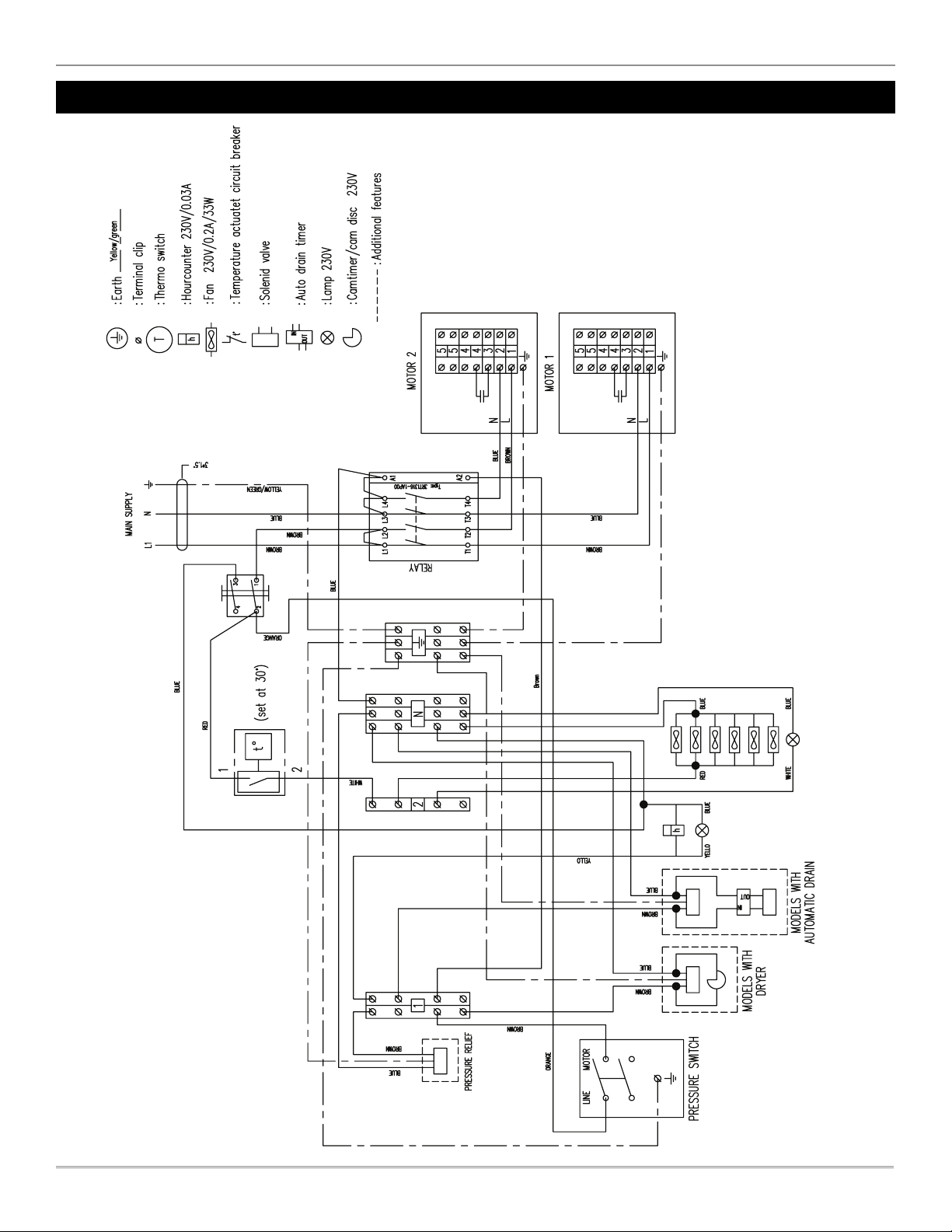
Electrical Drawing Model R-M and R-MQ, V// Hz
14
6190761 (Rev A) 120R Basic Compressor User Guide
© 2022, JUN-AIR
We reserve the right to make any alterations which may be due to any technical improvements
Printed in the USA
Electrical Drawing Model xR-M, xR-MQ, V// Hz

15
© 2022, JUN-AIR
We reserve the right to make any alterations which may be due to any technical improvements
Printed in the USA
120 Basic Compressor User Guide 6190761 (Rev A)
Compressor system
R-
PM-
NNX
Compressor
Receiver, l silver w/inspection plug internally coated for metal
cabinet ASME
Receiver l with inspection plug f/metal cabinet, silver
Receiver l for metal cabinet w/inspection plug silver internally
coated CE/ASME
Filter um w/automatic drain, complete
Regulator R--RNMG, bar
Panel ring f/regulator and filter regulator
Dryer complete xOF & OF OX Bar
Dryer complete xOF & OF OX Bar
Dryer complete OF C-D type OX Bar
Dryer complete OF C-D type OX Bar
Dryer complete xOF D-D type OX Bar
Dryer complete xOF D-D type OX Bar
Rapid fitting /” internal x Ø mm
Rapid fitting /” external x Ø
Rapid fitting elbow /”xØ
Rapid fitting elbow /”internal x Ø
Rapid fitting elbow /” int. x Ø
Rapid fitting elbow /”xØ
Rapid fitting elbow /”xØ
Rapid fitting /” x Ø
Rapid fitting elbow /”xØ KQL-S
Rapid fitting lead-in /”xØmm
Rapid fitting Ø-Ø mm pipe
Rapid fitting Ømmx/” elbow
Rapid fitting elbow /” nt. x Ø mm
Rapid fitting lead-in /” x Ø mm
Rapid fitting /” ext. x Ømm
Rapid fitting lead-in /” x Ø mm
Kontactor Danfoss C/xV -Hz
Contactor Danfoss C/V
Contact . kW V/V without neutral
Thermo relay .-.A Danfoss
Thermo relay .-.A Danfoss
Connector .Q yellow/green
Connector .Q grey
Plate f/connector
Cage clamp connector
Control lamp V
Control lamp V w/spade plug
Control lamp V
Hour counter V
Hour counter V
Hour counter -V/-Hz
Camtimer V compl.
Camtimer V complete
Thermo switch ajustable
Plug male -pole f/metal cabinet
Switch f/metal cabinet (green)
Switch f/metal cabinet (A)
Solenoid valve f/unloader V w/plug
Solenoid valve f/unloader V w/plug
Auto drain -V series
Auto drain V series
Pressure switch MDR / -way UL
Gauge Ø - bar /” built-in
Non return valve
Safety valve bar / psi
Safety valve bar / psi
Drain cock /” l
Safety valve TÜV . bar
Radiator f/radiator & fan box
Fan V x
Fan V x
Drain bottle multi l compl. for metal cabinet
O-ring f/” plug - x mm
O-ring f/plug Ø.x. f/OF
O-ring Øx f/ /” plug
Grommet black ØxØxmm
Cable relief PG
Distance bolt f/metal cabinet
Distance bolt long f/metal cabinet
Unbraco plug /”x
Unbraco plug /”
Unbraco bolt Mx
Unbraco bolt Mx original
Spring washer Ø.xØ.x.
Washer ØxØ.x
Nut /” flat
Star washer type M
Star washer type A M
Teflon hose /” cm
Teflon hose /” cm with elbow
Teflon hose /” cm with elbow
Teflon hose /” cm with elbow
Wheel Ø mm
Wheel Ø mm w/brake
Cabinet plate - complete f/-M(D), OF- M(D),
OF-M(D), -M(D), -M(D) w/wheels
RAL
Cabinet plate complete size C-MD
Cabinet plate complete size D-MD
Back B-M V Snapline
Back B-D V Snapline
Back B-D V Snapline
Door B-MD, C-MD and D-MD Snapline
Back C-MD V Snapline
Back C-MD V Snapline
Back D-MD Snapline
Front complete B-MD V Snapline
Front complete B-MD V Snapline
Front complete C-MD V Snapline
Front D-MD V Snapline
Mounting bracket complete D-D xOF xV Snapline
Mounting bracket complete D-M xOF xV Snapline
Mounting bracket complete D-M OF xV Snapline
Mounting bracket complete C-M OF xV Snapline
Mounting bracket complete C-D OF xV Snapline
Mounting bracket complete C-M OF xV Snapline
Mounting bracket complete C-M V (M V) Snapline
Mounting bracket complete D-M xOF V Snapline
Parts & Accessories List

16
6190761 (Rev A) 120R Basic Compressor User Guide
© 2022, JUN-AIR
We reserve the right to make any alterations which may be due to any technical improvements
Printed in the USA
Mounting bracket complete A-D & BD V Snapline
Mounting bracket complete A-D & BD V Snapline
Mounting bracket complete A-M & B-M V Snapline
Mounting bracket complete A-M & B-M V Snapline
Mounting bracket complete C-D V (M V) Snapline
Mounting bracket complete D-D xOF V Snapline
Mounting bracket complete D-D xOF V Snapline
Mounting bracket complete D-M xOF V Snapline
Mounting bracket complete C-MD V & V Snapline
Mounting bracket complete D-MD xOF Snapline
Mounting bracket complete B-MD OF & M & xOF
V Snapline
Mounting bracket complete B-MD OF & M & xOF
V Snapline
Mounting bracket size f/cabinet
Mounting bracket A & B
Mounting bracket size C
Mounting bracket D
Double nipple /”
Plug /”
Double nipple /” L= mm
Double nipple /” w/o-ring track
Double nipple /”x/”
Bushing f/metal cabinet /”
Bushing f/autodrain f/metal cabinet /”
Bushing nipple
Connection piece f/non-return valve
Coupling /”
Coupling /”
Adaptor -way
Adaptor f/-
Cross connector /”
Plug ” f/inspection
Plug /” f/inspection ASME
Plug /” f/OF
Elbow /” int./ext. KRG
Elbow /”
Bushing /” int. x /” ext.
Bushing /” x /”
Y-connection /” ( x int.)
Compressor motor
Capacitor, run complete uF f/OF/OF ( cm)
Nut M FZB
Nut M square, FZB
Screw Mx PH Torx
Double nipple /” w/o-ring track
Miscellaneous
K Preventative Maintenance Kit
K Service Kit
K Spare Parts Kit
Parts & Accessories List, continued

17
© 2022, JUN-AIR
We reserve the right to make any alterations which may be due to any technical improvements
Printed in the USA
120 Basic Compressor User Guide 6190761 (Rev A)
Spare Parts: Model R-MQ
6985922
A
7024002
120R689-T102-N800NX
6342250
5074800
6341750
6341750
6390000
6390000
6372600
6372600
7167201
4146200
7167215
4143500
A
B
4141601
6986026
6317100
6390200
7026001
4739340
6341750
2X
4785600
4750700
6342200
2X
7070901
7167102
4143502
6985928
6339900
2X
4146203
2X
478150
5
6342200
2X
4141620
2X
8008511
4146201
7052005
4141620
4094100
5447000
5612306
4783803
475000
2X
4752205
5150000
2X
4141860
4146200
6340500
4071020
4146200
4147000
4141820
4779901
4740400
4X
4750700
6342200
6951201
6951301
4146200
5422702
4146200
7160000
3512102
5451000
5416100

18
6190761 (Rev A) 120R Basic Compressor User Guide
© 2022, JUN-AIR
We reserve the right to make any alterations which may be due to any technical improvements
Printed in the USA
Spare Parts: Model R-M
A
7024002
120R689-T102-N800NX
6342250
A
B
4141601
6986026
6317100
6390200
7026001
6342200
2X
6339900
2X
4146203
2X
4781505
5447000
4783803
475000
2X
4752205
5150000
2X
4141860
4146200
6340500
4071020
4146200
4147000
4141820
4779901
4740400
4X
4750700
6342200
6951201
6951301
4146200
5422702
4146200
7160000
3512102
5451000
5416100
6984878
6984878 DETAIL
6985922
4146200
7167201
507480
0
6295510
7167215
6390000 6341750
4143502
4143500
7070901
4785600
4146200
4740400
4739340
6341800
4750700
6372600
4X
8081112
6314200
2X
6358000

19
© 2022, JUN-AIR
We reserve the right to make any alterations which may be due to any technical improvements
Printed in the USA
120 Basic Compressor User Guide 6190761 (Rev A)
Spare Parts: xR-M
4740400
4779901
4750700
4740400
6342200
4146200
7565000
4146800
5414500
7598500
4141820
7025000
4146200
5416100
7160000
6951301
6984523
COMPLETE
6951201
3512102
A-A 6457047
B-B 6457047
6295900
6984935
COMPLETE
6390200
6390200
5447000
5451000
6317001
6390060
5240607
4141601
6317100
6390200
4146203
4146203
6339900
6339900
6340500
407102
0
4146200
4147000
4750001
4783803
4752000
4141820
4141860
5150000
6984919
COMPLETE
5612306
COMPLETE
7026001
6984974
COMPLETE
6984563
COMPLETE
6390025
6342250
A
6341060
B
4146200
6984949
COMPLETE
A
B
6372600
6341750
6390000
4141800
6390000
6342200
4146200
4071009
7024000
7167215
5074800
7167201
4146200
4785600
7020000
7167102
4141800
4147000
7076000
7025000
4799700
4146800
7167102
7083000
4141860
4146200
6221000
7022100
4750700
6341800
4740400
4739312
4740400
7024002
4146459
120R689-T102-N800NX
5414500

20
6190761 (Rev A) 120R Basic Compressor User Guide
© 2022, JUN-AIR
We reserve the right to make any alterations which may be due to any technical improvements
Printed in the USA
Spare Parts: Model xR-MQ
4143500
4143502
4785600
7167102
7070901
5447000
4141601
5451000
6390200
6390200
6390060
6317001
6984982
COMPLETE
6295900
6339900
4146203
6339900
5612302
COMPLETE
B-B 6457037
A-A 6457037
6984563
COMPLETE
120R689-T102-N800NX
7167201
6243710 O-RING
7024002
6243710 O-RING
6342250
6355500
6984523
COMPLETE
6951201
6951301
4146200
5422702
5240600
5416100
7160000
4146200
4750700
6342200
4779901
4740400
6984990
COMPLETE
4783803
4750001
4752205
4141820
4141860
5150000
4146200
6340500
4071021
4146200
4147000
6984974
COMPLETE
5451000
4141620
8008511
4094200
7022100
6221000
4141860
4141860
4146200
5414500
7083000
7167102
6342200
6358000
8081112
4740400
4739340
4740400
6341750
4750700
6342200
639000
0
6372600
6341750
6390000
6372600
6341750
6390000
6341750
6390000
6342200
7167215
6243710 O-RING
5074800
7167201
6243710
O-RING
4146200
4146200
4750700
4740400
4739342
4740400
6342200
5240600
6985973
6984919
COMPLETE
A
7026001
6390200
6317100
B
C
C
A
6342200
4146458
4146458
6985948
7052005
4146200
3512102
6372600
Other manuals for 120R
1
This manual suits for next models
3
Other Gast Air Compressor manuals


Popular Air Compressor manuals by other brands


ActiveProducts
ActiveProducts C36A-54 owner's manual

Central Pneumatic
Central Pneumatic 93351 Assembly and operating instructions

MasterFlow
MasterFlow MF-1089 owner's manual

Airmax
Airmax SilentAir G25 installation manual

Delta
Delta A08590 instruction manual

ALLPOWER
ALLPOWER 3.5HP PEAK 6 GALLON owner's manual


