Gast DDL15 Manual
A Unit of Corporation
ISO 9001 &14001 CERTIFIED
1
Life
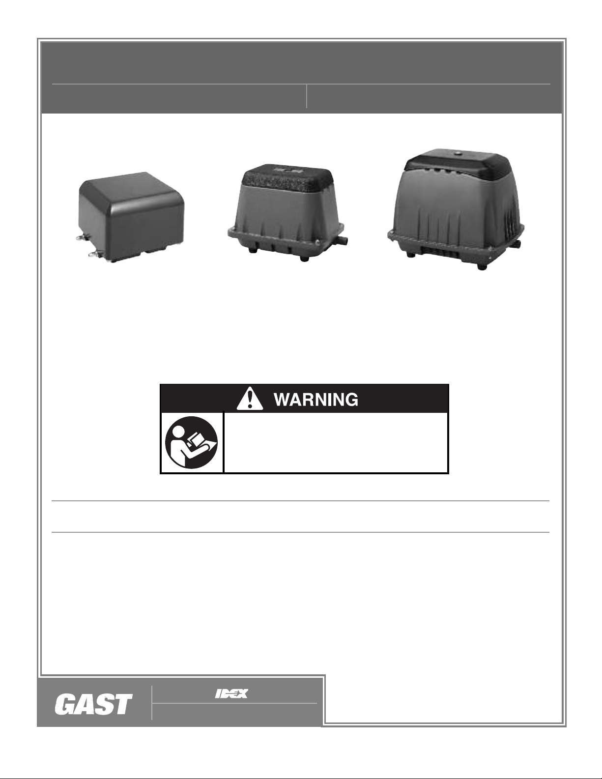
LINEAR OILLESS COMPRESSORS
OPERATION & MAINTENANCE MANUAL PART NO. 70-1570 F1-210 (REV. F)
Product Use Criteria
Depends upon speed, operating pressure and motor maintenance
• Pump only clean, dry air.
• Operate at 40ºF - 104ºF (4.4ºC - 40ºC)
• Protect unit from dirt and moisture.
• Do not pump flammable or explosive gases or use in an atmosphere that contains
such gases.
• Corrosive gases and particulate material will damage unit. Water vapor, oil-based
contaminants or other liquids must be filtered out.
• Oil-less compressors require NO lubrication
• Consult your Gast Distributor/Representative before using at high altitudes.
www.gastmfg.com
䊛Registered Trademar /姠Trademar of Gast Manufacturing Inc., Copyright 䊚2002 Gast Manufacturing Inc. All Rights Reserved.
PLEASE READ THIS MANUAL COMPLETELY
BEFORE INSTALLING AND USING THIS MOTOR.
SAVE THIS MANUAL FOR FUTURE REFERENCE
AND KEEP IN THE VICINITY OF THE MOTOR.
Thank you for purchasing this Gast product.
It is manufactured to the highest standards using quality materials.
Please follow all recommended maintenance, operational and safety
instructions and you will receive years of trouble-free service.
DDL15 DBM40-DBM80 DBMX100

In the event of an electrical short circuit, grounding
reduces the risk of electric shock by providing an
escape wire for the electric current. This product may
be equipped with a power supply cord having a
grounding wire with an appropriate grounding plug.
The plug must be plugged into an outlet that is properly
installed and grounded in accordance with all local
codes and ordinances.
Check with a qualified electrician or serviceman if
the grounding instructions are not completely
understood, or if you are not sure whether the
product is properly grounded. Do not modify the
plug provided. If it will not fit the outlet, have the
proper outlet installed by a qualified electrician.
INSTALLATION
c
Disconnect electrical power at the circuit breaker
or fuse box before installing this product.
Install this product where it will not come into
contact with water or other liquids.
Install this product where it will be weather
protected.
Electrically ground this product.
Failure to follow these instructions can result in
death, fire or electrical shock.
WARNING
Electrical Shock Hazard
Plumbing
Remove plug from the OUT port. Connect with pipe
and fittings that are the same size or larger than the
product’s port.
Accessories
Install relief valve and gauge at outlet to monitor
performance. A check valve may be required to
prevent back streaming through the compressor.
Motor Control
It is your responsibility to contact a qualified
electrician and assure that the electrical installation
is adequate and in conformance with all national
and local codes and ordinances.
Correct installation is your responsibility. Make sure
you have the proper installation conditions and that
installation clearances do not block air flow.
Mounting
This product must be installed on a flat, horizontal
surface. Mounting the product to a stable, rigid
operating surface and using shock mounts will reduce
noise and vibration.
WARNING
DANGER
Your safety and the safety of others
isextremely important.
We have provided many important safety messages
in this manual and on your product. Always read
and obey all safety messages.
This is the safety alert symbol. This symbol
alerts you to hazards that can kill or hurt you and
others. The safety alert symbol and the words
“DANGER” and “WARNING” will precede all safety
messages. These words mean:
You will be killed or seriously injured if you don’t
follow instructions.
You can be killed or seriously injured if you don’t
follow instructions.
All safety messages will identify the hazard, tell you
how to reduce the chance of injury, and tell you
what can happen if the safety instructions are not
followed.
2
c
This product must be properly grounded.
Do not modify the plug provided. If it will not
fit the outlet, have the proper outlet installed
by a qualified electrician.
If repair or replacement of the cord or plug is
necessary, do not connect the grounding wire
to either flat blade terminal. The wire with
insulation that is green with or without yellow
stripes is the grounding wire.
Check the condition of the power supply wiring.
Do not permanently connect this product to
wiring that is not in good condition or is
inadequate for the requirements of this product.
Failure to follow these instructions can result in
death, fire or electrical shock.
WARNING
Electrical Shock Hazard
ELECTRICAL CONNECTION

DIAGRAM B
Minimum Gage For Extension Cords
Amps Volts Length of cord in feet
120v 25 50 100 150 200 250 300 400 500
240v 50 100 200 300 400 500 600 800 1000
0-2 18 18 18 16 16 14 14 12 12
2-3 18 18 16 14 14 12 12 10 10
3-4 18 18 16 14 12 12 10 10 8
4-5 18 18 14 12 12 10 10 88
5-6 18 16 14 12 10 10 888
6-8 18 16 12 10 10 8666
8-10 18 14 12 10 88664
3
Model that is permanently wired
This product must be connected to a grounded,
metallic, permanent wiring system, or an equipment
grounding terminal or lead on the product.
Power supply wiring must conform to all required safety
codes and be installed by a qualified person. Check
that supply voltage agrees with that listed on product
nameplate.
Extension cords
Use only a 3-wire extension cord that has a 3-blade
grounding plug. Connect extension cord plug to a
matching 3-slot receptacle. Do not use an adapter. Make
sure your extension cord is in good condition. Check that
the wire gage of the extension cord is the correct size wire
to carry the current this product will draw. An undersized
cord is a potential fire hazard, and will cause a drop in line
voltage resulting in loss of power causing the product to
overheat. DIAGRAM B indicates the correct gage cord for
length required and the ampere rating listed on the product
nameplate.
If in doubt, use the next heavier gage cord. The smaller
the gage number, the heavier the wire gage.
Model with a power supply cord
This product must be grounded. For either 120-volt or
220/240-volt circuits connect power supply cord
grounding plug to a matching grounded outlet. Do not
use an adapter. (See DIAGRAM A)
Grounded Plug
Grounding Pin
Grounded Outlet
120-volt grounded connectors
shown. 220/240-volt grounded
connectors will differ in shape.
DIAGRAM A
OPERATION
Injury Hazard
Use only recommended air handling parts
acceptable for pressure not less than 10 psi.
When provided, motor terminal covers must be in
place for safe operation.
Product surfaces may become hot during operation,
allow product surfaces to cool before handling.
Do Not direct air stream at body. Air stream from
product may contain solid or liquid material that can
result in eye or skin damage, wear proper eye
protection.
Do Not spray flammable or combustible liquid.
Failure to follow these instructions can result in
burns, eye injury or other serious injury.
WARNING
DIAGRAM C
Start Up
If pump fails to start or slows down significantly under load,
shut off and disconnect from power supply. Check that the
voltage is correct for the pump.
Safety switch system(only in DBMX and DBMS series)
When diaphragm is broken, the protrusion on top of the
magnet frame will activate microswitch and shut down the
power to prevent further damage.
Alarm control system( optional )
The control is equipped with a three position toggle switch
(DIAGRAM C). Operation in each switch position is as follows.
RUN
During normal operation the switch is in the RUN or
center position. The unit will function fully automated in
the RUN mode. In the event of two pressure situation
( low or high pressure) the controller will sound an alarm
and light a visual indicator light to attract the operator of
those conditions (lower & higher pressure).
MUTE
The MUTE position will allow the unit to continue to run
but will silence the audible alarm while leaving the visual
alarm active.
TEST
The TEST position will activate both the
audible and visual alarms to check to
see if they are functioning properly.
4
MAINTENANCE
c
Disconnect electrical power supply cord before
performing maintenance on this product.
If product is hard wired into system, disconnect
electrical power at the circuit breaker or fuse box
before performing maintenance on this product.
Failure to follow these instructions can result in
death, fire or electrical shock.
Electrical Shock Hazard
WARNING
Guidelines for aquarium use
1. Close supervision is necessary when any air pump
is used by or near children.
2. To avoid injury, DO NOT disassemble the air pump.
3. Always unplug an air pump from an outlet when not
in use, before putting on or taking off parts and
before cleaning. NEVER yank a cord to remove the
plug from the receptacle. Grasp the plug and pull
to disconnect.
4. DO NOT use an aquarium air pump for other than
its intended use. The use of attachments which are
not recommended or sold by Gast Manufacturing
may cause an unsafe condition.
5. DO NOT install or store the air pump where it will be
exposed to the weather or to temperatures below
freezing.
6. Make sure an air pump mounted on a tank is
securely installed before operating it.
7. Read and observe all the important notices on the
air pump.
Injury Hazard
Product surfaces may become hot during operation,
allow product surfaces to cool before handling.
Do Not direct air stream at body. Air stream from
product may contain solid or liquid material that can
result in eye or skin damage, wear proper eye
protection.
Clean this product in a well ventilated area.
Failure to follow these instructions can result in
burns, eye injury or other serious injury.
WARNING
SAVE THESE INSTRUCTIONS.
WARNING – Read and follow all safety instructions.
To guard against injury, basic safety precautions
should be observed.
DANGER – To avoid possible electrical shock,
special care should be taken since water is
employed in the use of aquarium equipment. If the
air pump, cord or plug are damaged in any way
whatsoever, DO NOT attempt repairs by yourself,
return the air pump to a Gast Authorized Service
Facility for inspection and repair.
Precautions for aquarium use
1. If the air pump falls into the water, DO NOT reach
into the water to retrieve it.
2. Carefully examine the appliance after installation.
It should not be plugged into electrical power if there
is water found on any part of the pump.
3. DO NOT operate any air pump if it has a damaged
cord or plug, or if it is malfunctioning or has been
dropped or damaged in any manner.
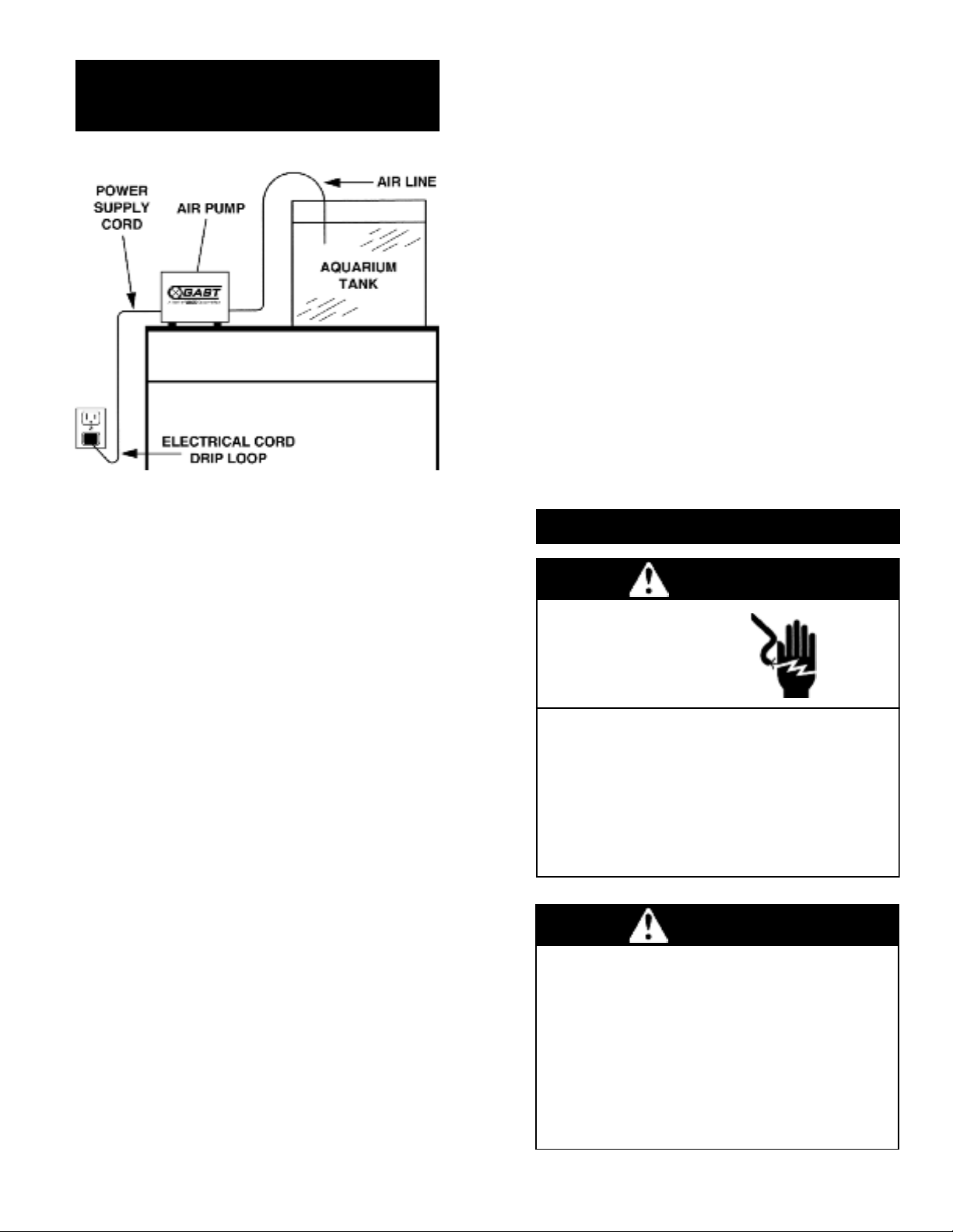
4. To avoid the possibility of the air pump plug or
receptacle getting wet, position the aquarium stand
and tank to one side of a wall-mounted receptacle to
prevent water from dripping onto the receptacle or
plug. A “drip loop,” shown above in the AQUARIUM
SETUP DIAGRAM, should be arranged by the user
for each cord connecting an aquarium air pump to a
receptacle. The “drip loop” is that part of the cord
below the level of the receptacle, or the connector if
an extension cord is used, which prevents water
travelling along the cord from coming into contact
with the receptacle.
5. If the plug or receptacle do get wet, DO NOT grasp
the plug to disconnect the air pump. Instead
disconnect the fuse or circuit breaker supplying
power to the receptacle. Then unplug the air pump
and examine for the presence of water on the plug
or receptacle.
AQUARIUM SETUP DIAGRAM
IMPORTANT SAFETY INSTRUCTIONS
FOR AQUARIUM USE

5
It is your responsibility to
• Regularly inspect and make necessary repairs to
product in order to maintain proper operation.
• Make sure that pressure is released from product
before starting maintenance.
• Never add oil to this oil-less compressor.
Check intake filter after first 500 hours of operation. Clean
filter and determine how frequently filter should be checked
during future operation. This one procedure will help to
assure the product’s performance and service life.
Cleaning
Do Not use kerosene or ANY other combustible solvent
to clean product.
To clean the air filter (Recommended once every six months)
1. Loosen the screw on top (Refer to Diagram D and E).
2. Remove filter cover.
3. Take the filter out and clean it with clean water and dry it.
4. Put it back and secure the fixing plate with the screw in.
Check that all external accessories such as relief valves
and gauges are attached to cover and are not damaged
before re-operating product.
FILTER
FILTER
DIAGRAM E
DIAGRAM D
MAINTENANCE RECORD
DATE PROCEDURE PERFORMED

6
Gast will NOT guarantee field-rebuilt product
performance.
For performance guarantee, the product must be returned
to a Gast Authorized Service Facility.
Service it contents vary with compressor models.
If compressor still does not produce proper pressure,
send unit to a Gast Authorized Service Facility for repair.
Disassembly
1. Remove hex nuts from cover(Diagram F).
2. Remove cover and cover gasket.
3. Gently lift out electromagnet and casing block.
4. Remove head asembly from diaphragm casing
block, discard if replacing.
5. Remove phillips screw from center of diaphragm
and remove the diaphragm.
Re-assembly
1. Reinstall new diaphragm, make sure it fits securely
into diaphagm casing (note the two locating notches
for re-assembly).
2. Reinstall and tighten the phillips screw
3. Reinstall or replace the head assembly.
3. Fit electromagnet unit over casing mechanism and fit
components back into housing of pump
4. Reinstall cover gasket and cover.
5. Tighten hex nuts in place
Replacing Head and Diaphragm Assemblies
(DDL )
DIAGRAM F
60 Hz 50 Hz
DDL5 898 -- N/A
DDL8 890 -- N/A
DDL8B 890 -- N/A
DDL15 890 -- N/A
DDL15B 890 -- N/A
DDL30 887 932 891
DDL30B 887 932 N/A
DDL40 887 932 891
DDL40B 887 932 N/A
DDL60 888 931 891
DDL80 888 931 891
DDL120 889 930 892
DDL150 889 930 892
DBP25 941 941A N/A
DBP40 943 943 891A
DBM30B 947 947A N/A
DBM20 951 951 N/A
DBM40 942 942 891B
DBM60 944 944A 891B
DBM80 950 950A 891B
DBMS60 -- 952A 891B
DBMS80 -- 953A 891B
DBMS600 944 -- 891B
DBMS800 950 -- 891B
DBMX80 945 945A 891
DBMX100 949 949A 891
DBMX120 956 956 891
DBMX150 946 946 891C
DBMX200 946 946 891C
MODEL DIAPHRAGM FILTER
& HEAD ASSY
SERVICE KIT INSTALLATION
c
Disconnect electrical power supply cord before
installing Service Kit.
If product is hard wired into system, disconnect
electrical power at the circuit breaker or fuse box
before installing Service Kit.
Disconnect air supply and vent all air lines to
release pressure or vacuum.
Failure to follow these instructions can result in
death, fire or electrical shock.
WARNING
Electrical Shock Hazard
SERVICE KITS*
* The service kit may contain parts for more than one
model or style of linear pump. Parts not needed may
be discarded. its listed are for stock models.
For specific OEM models, please consult the factory.
When corresponding or ordering kits, please give
complete model and serial numbers.

Replacing Head and Diaphragm Assemblies
(DDL40-80, DBP, DBM40-80)
Replacing Head and Diaphragm Assemblies
(DBMX MODELS)
IMPORTANT To open the upper housing, please make sure you
have unplugged the power cord before opening.
1. Loosen the screws around the upper housing,
and take the housing off. (Diagram G)
2. Loosen the four screws and disassemble the parts. (Diagram H)
3. Loosen the u-nut in the center of diaphragm.
4. Take the diaphragm off its place.
5. Replace a new one by mounting the rubber studs
into their position.
6. Press the rim of the diaphragm into the ring.
7. Secure the magnet with a new u-nut and screw and put the
diaphragm housing back with the four screws on.
IMPORTANT To open the upper housing, please make sure you
have unplugged the power cord before opening.
1. Loosen the four screws around the upper housing, and take the housing
off. (Diagram I)
2. Loosen the four screws around the coil cover, and take the cover off.
(Diagram J)
3. Loosen the four screws and disassemble the diaphragm housing.
4. Loosen the u-nut in the center of diaphragm.
5. Take the diaphragm off its place.
6. Replace a new one by mounting the rubber studs into their position.
7. Press the rim of the diaphragm into the ring.
8. Secure the magnet with a new u-nut and screw and put the diaphragm
housing back with the four screws on.
9. Put the coil cover back with the four screws on.
10. Put on the aluminum cover and secure the four screws firmly.
7
DIAGRAM G DIAGRAM H
DIAGRAM I DIAGRAM J
DBM40, 60, 80
DBP40
ijĴĵĶIJķĸĹĺIJıIJIJIJijIJĴIJĵIJĶIJķIJĸIJĹIJĺijıijIJijijijĴijĵijĶijķijĸ
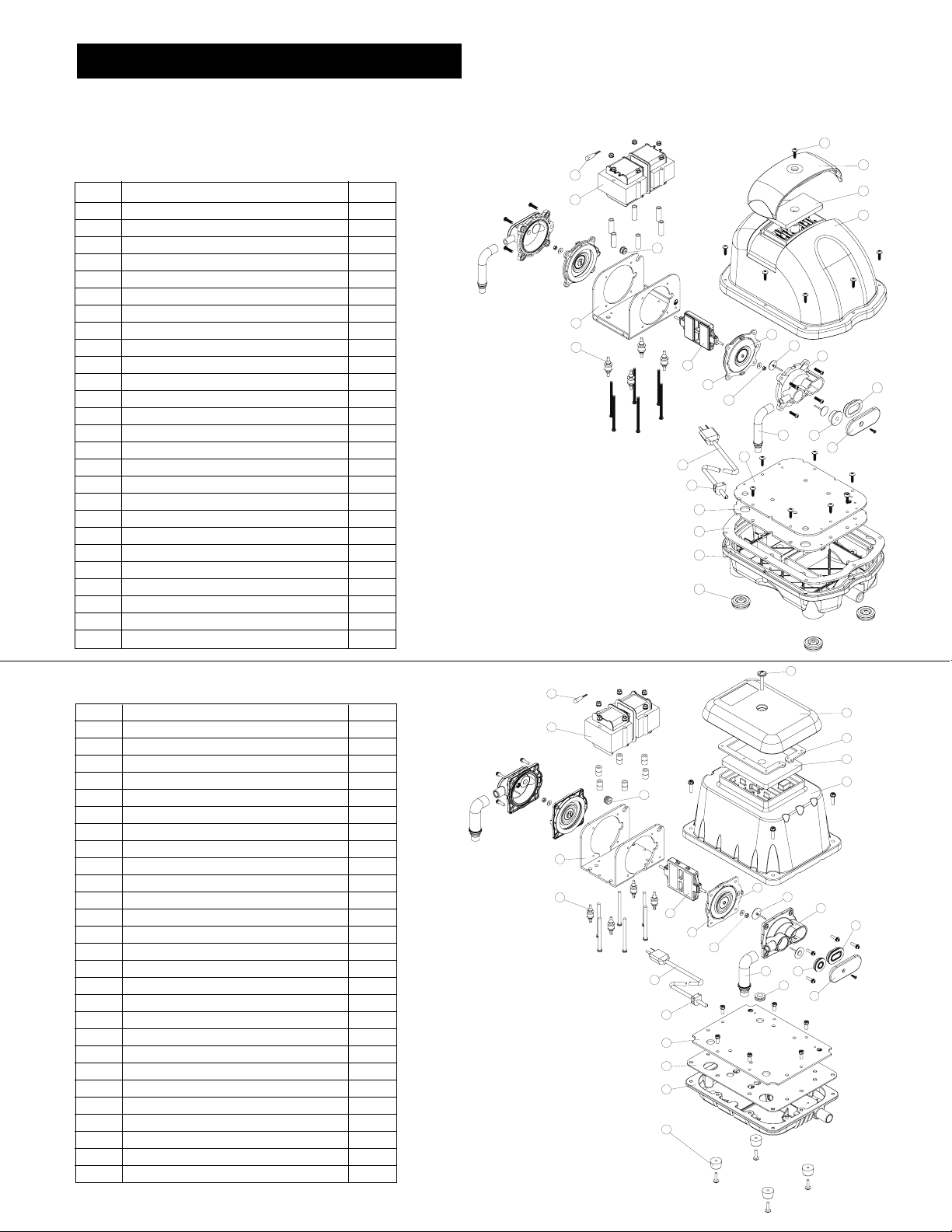
EXPLODED PRODUCT VIEW & PARTS
* Your model may vary in appearance and configuration. However, internal components will be similar to those shown.
Parts shown are for stock models. For specific OEM models, please consult the factory.
When corresponding or ordering kits, please give complete model and serial numbers.
ĴĵĶķĸĹĺIJıIJijIJĴIJIJIJIJĵIJķIJĶIJĸIJĹIJĺijıijIJijijijĴijĵijĶijķij
NO. DESCRIPTION QTY
1 TOP SCREW 1
2 FILTER COVER 1
3 FOAM SEAL 1
4 FILTER 1
5 UPPER HOUSING 1
6 THERMOSTAT 1
7 ELECTROMAGNET 2
8 WIRE STOPPER 1
9 U-SHAPED COIL FRAME 1
10 VIBRATION CONTROL RUBBER 4
11 ACTIVATING ARM 1
12 DIAPHRAGM 2
13 DIAPHRAGM FRAME 2
14 U NUT 2
15 CHEC VALVE 4
16 L – TUBE 2
17 DIAPHRAGM HOUSING 2
18 CHAMBER SEAL (ROUND) 2
19 CHAMBER SEAL (OVAL) 2
20 SIDE COVER (STEEL) 2
21 CORD PROTECTOR 1
22 STEEL PLATE 1
23 GAS ET 1
24 LOWER HOUSING 1
25 RUBBER FEET 4
26 CORD RELIEF 1
27 POWER CORD 1
NO. DESCRIPTION QTY
1 TOP SCREW 1
2 FILTER COVER 1
3 FILTER 1
4 UPPER HOUSING 1
5 THERMOSTAT 1
6 ELECTROMAGNET 2
7 WIRE STOPPER 1
8 U-SHAPED COIL FRAME 1
9 VIBRATION CONTROL RUBBER 4
10 ACTIVATING ARM 1
11 DIAPHRAGM 2
12 DIAPHRAGM FRAME 2
13 U NUT 2
14 CHEC VALVE 4
15 L - TUBE 2
16 DIAPHRAGM HOUSING 2
17 CHAMBER SEAL (ROUND) 2
18 CHAMBER SEAL (OVAL) 2
19 SIDE COVER (STEEL) 2
20 STEEL PLATE 1
21 GAS ET 1
22 GAS ET 1
23 LOWER HOUSING 1
24 RUBBER FEET 4
25 CORD RELIEF 1
26 POWER CORD 1
8

DDL40, 60, 80
ĴĵĸIJIJIJĴIJĸIJĶijijijĶIJķĹĺIJıIJijIJĵIJķIJĹIJĺijıijIJijĴijĵijĶijķ
NO. DESCRIPTION QTY
1 TOP SCREW 1
2 FILTER COVER 1
3 FOAM SEAL 1
4 FILTER 1
5 UPPER HOUSING 1
6 THERMOSTAT 1
7 ELECTROMAGNET 2
8 WIRE STOPPER 1
9 U-SHAPED COIL FRAME 1
10 VIBRATION CONTROL RUBBER 4
11 ACTIVATING ARM 1
12 DIAPHRAGM 2
13 DIAPHRAGM FRAME 2
14 U NUT 2
15 CHEC VALVE 4
16 L - TUBE 2
17 DIAPHRAGM HOUSING 2
18 CHAMBER SEAL (ROUND) 2
19 CHAMBER SEAL (OVAL) 2
20 SIDE COVER (STEEL) 2
21 STEEL PLATE 1
22 GAS ET 1
23 LOWER HOUSING 1
24 RUBBER FEET 4
25 CORD RELIEF 1
26 POWER CORD 1
9
NO. DESCRIPTION QTY
1 TOP SCREW 1
2 FILTER COVER 1
3 FILTER 1
4 UPPER HOUSING 1
5 COIL COVER 1
6 SAFETY SYSTEM IT 1
7 THERMOSTAT 1
8 ELECTORMAGNET 2
9 WIRE STOPPER 1
10 COIL FRAME 1
11 VIBRATION CONTROL RUBBER 4
12 ACTIVATING ARM 1
13 DIAPHRAGM 2
14 DIAPHRAGM FRAME 2
15 U NUT 2
16 CHEC VALVE 4
17 L – TUBE 2
18 DIAPHRAGM HOUSING 2
19 CHAMBER SEAL (ROUND) 2
20 CHAMBER SEAL (OVAL) 2
21 SIDE COVER (STEEL) 2
22 STEEL PLATE 1
23 GAS ET 1
24 LOWER HOUSING 1
25 RUBBER FEET 4
26 POWER CORD 1
IJijĴĵĶķĸĹĺIJıIJIJIJijIJĴIJĵIJĶIJķIJĹIJĸIJĺijıijIJijijijĴijĵijĶijķ
DBMX80, 100, 120
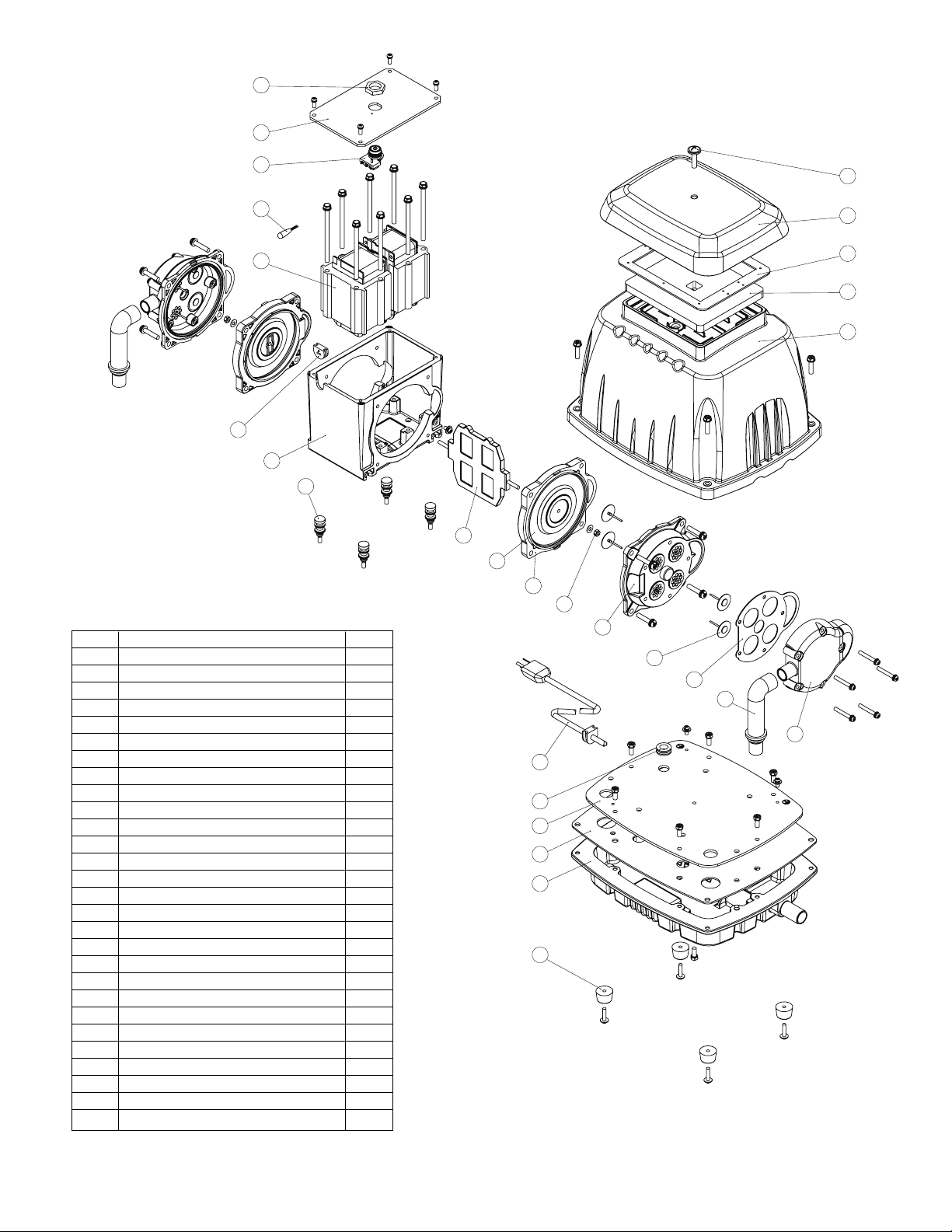
NO. DESCRIPTION QTY
1 TOP SCREW 1
2 FILTER COVER 1
3 FOAM SEAL 1
4 FILTER 1
5 UPPER HOUSING 1
6 SAFETY SYSTEM NUT 1
7 COIL COVER 1
8 SAFETY SYSTEM IT 1
9 THERMOSTAT 1
10 ELECTORMAGNET 2
11 WIRE STOPPER 1
12 COIL FRAME 1
13 VIBRATION CONTROL RUBBER 4
14 ACTIVATING ARM 1
15 DIAPHRAGM 2
16 DIAPHRAGM FRAME 2
17 U – NUT 2
18 DIAPHRAGM HOUSING 2
19 CHEC VALVE 8
20 GAS ET - 1 2
21 L – TUBE 2
22 DIAPHRAGM HOUSING COVER 2
23 POWER CORD 1
24 CORD PROTECTOR 1
25 STEEL PLATE 1
26 GAS ET - 2 1
27 LOWER HOUSING 1
28 RUBBER FEET 4
IJijĴĵĶĸķĹĺIJıIJIJIJijIJĴIJĵIJķIJĶIJĸijIJijıIJĺIJĹijĵijĶijķijĸijĹijĴijij
DBMX1 0, 200
10

11
Low High Pump Motor Excess Reason and remedy
Pressure Pressure Overheat Overload Noise for problem.
• Filter dirty.
Clean or replace.
• Valves dirty or valves bent.
Clean or replace.
•••Worn or torn diaphragm.
Repair or replace.
• Relief valve set too high.
Inspect and adjust.
• Relief valve set too low.
Inspect and adjust.
• Plugged pressure line.
Inspect and repair.
• Low voltage, won’t start.
Check power source.
••••Voltage wrong.
Check power source.
••Rod magnet misalignment.
Realign.
• Leaky hose or check valve.
Replace.
••••Dirt or liquid in compressor.
Inspect and clean.
••Blown or leaking head gasket
or tubes. Replace.
TROUBLESHOOTING CHART
AUnitof Corporation
ISO 9001 &14001 CERTIFIED
LINEAR OILLESS COMPRESSORS PART NO. 70-1570 F1-210 (REV. F)
World Headquarters
GAST Manufacturing Inc.
A Unit of IDEX Corporation
2300 M-139 Highway
Benton Harbor, Michigan 49022
Phone 269-926-6171
Fax 269-925-8288
GAST Hong Kong
Room 6/9F, New Commerce
Centre
19 On Sum St., Shatin
N.T., Hong ong
Phone 852-2690-1008
Fax 852-2690-1012
GAST GROUP LTD
A unit of IDEX Corporation
Unit 11, The I O Centre
Nash Road
Redditch, B98 7AS
United ingdom
Phone +44 (0)1527 504040
Fax +44 (0)1527 525262
For the name of the nearest authorized service facility, contact one of our offices below or visit
our website at www.gastmfg.com.
Gast finished products, when properly installed and operated under normal conditions of use, are warranted by Gast to
be free from defects in material and workmanship for a period of twelve (12) months from the date of purchase from Gast
or an authorized Gast Representative or Distributor. In order to obtain performance under this warranty, the buyer must
promptly (in no event later than thirty (30) days after discovery of the defect) give written notice of the defect to Gast
Manufacturing Incorporated, PO Box 97, Benton Harbor Michigan USA 49023-0097 or an authorized Service Center
(unless specifically agreed upon in writing signed by both parties or specified in writing as part of a Gast OEM Quotation).
Buyer is responsible for freight charges both to and from Gast in all cases.
This warranty does not apply to electric motors, electrical controls, and gasoline engines not supplied by Gast. Gast’s
warranties also do not extend to any goods or parts which have been subjected to misuse, lack of maintenance, neglect,
damage by accident or transit damage.
THIS EXPRESS WARRANTY EXCLUDES ALL OTHER WARRANTIES OR REPRESENTATIONS EXPRESSED OR IMPLIED
BY ANY LITERATURE, DATA, OR PERSON. GAST’S MAXIMUM LIABILITY UNDER THIS EXCLUSIVE REMEDY SHALL
NEVER EXCEED THE COST OF THE SUBJECT PRODUCT AND GAST RESERVES THE RIGHT, AT ITS SOLE
DISCRETION, TO REFUND THE PURCHASE PRICE IN LIEU OF REPAIR OR REPLACEMENT.
GAST WILL NOT BE RESPONSIBLE OR LIABLE FOR INDIRECT OR CONSEQUENTIAL DAMAGES OF ANY IND,
however arising, including but not limited to those for use of any products, loss of time, inconvenience, lost profit, labor
charges, or other incidental or consequential damages with respect to persons, business, or property, whether as a result
of breach of warranty, negligence or otherwise. Notwithstanding any other provision of this warranty, BUYER’S REMEDY
AGAINST GAST FOR GOODS SUPPLIED OR FOR NON-DELIVERED GOODS OR FAILURE TO FURNISH GOODS,
WHETHER OR NOT BASED ON NEGLIGENCE, STRICT LIABILITY OR BREACH OF EXPRESS OR IMPLIED WARRANTY
IS LIMITED SOLELY, AT GAST’S OPTION, TO REPLACEMENT OF OR CURE OF SUCH NONCONFORMING OR NON-
DELIVERED GOODS OR RETURN OF THE PURCHASE PRICE FOR SUCH GOODS AND IN NO EVENT SHALL EXCEED
THE PRICE OR CHARGE FOR SUCH GOODS. GAST EXPRESSLY DISCLAIMS ANY WARRANTY OF MERCHANTABILITY
OR FITNESS FOR A PARTICULAR USE OR PURPOSE WITH RESPECT TO THE GOODS SOLD. THERE ARE NO
WARRANTIES WHICH EXTEND BEYOND THE DESCRIPTIONS SET FORTH IN THIS WARRANTY, notwithstanding any
knowledge of Gast regarding the use or uses intended to be made of goods, proposed changes or additions to goods, or
any assistance or suggestions that may have been made by Gast personnel.
Unauthorized extensions of warranties by the customer shall remain the customer’s responsibility.
CUSTOMER IS RESPONSIBLE FOR DETERMINING THE SUITABILITY OF GAST PRODUCTS FOR CUSTOMER’S USE
OR RESALE, OR FOR INCORPORATING THEM INTO OBJECTS OR APPLICATIONS WHICH CUSTOMER DESIGNS,
ASSEMBLES, CONSTRUCTS OR MANUFACTURES.
This warranty can be modified only by authorized Gast personnel by signing a specific, written description of any
modifications.
WARRANTY
This manual suits for next models
3
Table of contents
Other Gast Air Compressor manuals


