Gast JUN-AIR 106R-4M User manual

Part No. 6190759 (Rev B)
106R-4M, 106R-25M, 106R-25MQ2,
2x10⁶R-40M, 2x10⁶R-40MQ2
6190759 | REV B
® Registered Trademark/™ Trademark of JUN-AIR Inc. ©Copyright 2023 JUN-AIR Manufacturing Inc. All Rights Reserved.
WWW
.
JUN
-
AIR
.
COM
ISO 9001 CERTIFIED
A BRAND OF
®
Cabinet Systems
A BRAND OF
®

2
6190759 (Rev B) 106R Cabinet Systems User Guide
© 2023, JUN-AIR
We reserve the right to make any alterations which may be due to any technical improvements
Printed in the USA
Table of Contents
Operating Manual .................................................................................................4
Technical Specifications........................................................................................... 9
Diagrams.........................................................................................................11
Kits ...............................................................................................................21
Feature Diagrams ................................................................................................22
Symbols .........................................................................................................30
3
© 2023, JUN-AIR
We reserve the right to make any alterations which may be due to any technical improvements
Printed in the USA
106R Cabinet Systems User Guide 6190759 (Rev B)
SAFETY
Important - read this first!
Please read the following information and operating instructions
included with this product before use. This information is for your
safety and it is important that you follow these instructions. It will
also help prevent damage to the product. Failure to operate the unit
in accordance with the instructions or using JUN-AIR unauthorized
spare parts can cause damage to the unit and could cause serious
injury.
IMPORTANT: General instructions for installation
• If the compressor is not fitted with a supply plug, a circuit
breaker must be incorporated in the fixed wiring.
• If this unit is supplied with a three-pin plug, connect with a
properly grounded outlet only.
CAUTION: To reduce risk of electric shock
• Only authorized service agents should carry out service.
Removing parts or attempting repairs can create an electric
shock. Refer all servicing to qualified service agents.
WARNING: To reduce risk of electrocution
• Do not use this unit with electrical voltages other than stated
on the rating plate.
• Always unplug this unit immediately after use and store in a dry
place.
• Do not use this product in or near liquid or where it can fall or
be pulled into water or other liquids.
• Do not reach for this product if it has fallen into liquid. Unplug
immediately.
• This unit is not weatherproof. Never operate outdoors in the
rain or in a wet area.
DANGER: To reduce risk of explosion or fire
• During spraying with combustible liquids, risk of explosion may
arise, particularly in closed rooms.
• Do not use this product in or near explosive atmospheres or
where aerosol products are being used.
• Do not pump any other gases other than atmospheric air.
• Do not pump combustible liquids or vapors with this product;
do not use it in or near areas with combustible or explosive
liquids or vapors.
• Do not use this unit near open flames.
CAUTION: To prevent injury
• Compressed air can be dangerous; do not direct airflow at
a person’s head or body.
• Always keep the system out of reach of children.
• Never operate this product if it has a damaged power lead or
plug, if it has been dropped or damaged, or if it has fallen into
water. Return the product to a service center for examination
and repair.
• Keep the electrical cable away from hot surfaces.
• Ensure all openings are kept free of restriction, and never
place the motor on a soft surface where the openings may
be blocked. Keep all openings free from dust, dirt and other
particles.
• Never leave this product unattended when plugged in.
• Never insert fingers or any other objects into fans.
• This unit is thermally protected and can automatically restart
when the overload resets.
• Wear safety glasses, when servicing this product.
• Use only in well ventilated areas.
• This product may only be connected to units or tools with a
max. pressure rating higher or equal to that of the compressor.
• The surface of the compressor can get hot. Do not touch
compressor motor during operation.
Failure to observe the safety precautions could result in severe
bodily injury, including death in extreme cases.
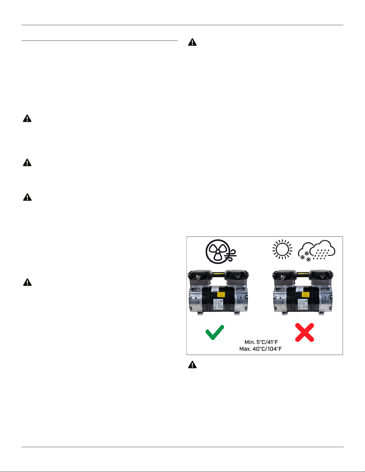
IMPORTANT: General directions for use
• Protect compressor against rain, moisture, frost and dust.
• The compressor is constructed and approved for a max.
pressure as stated under Technical Specifications.
• Do not operate the compressor at ambient temperatures
exceeding 40°C/104°F or falling below 0°C/32°F.
• If the supply power lead on the compressor is defective, an
authorized Jun-Air distributor or other qualified personnel
must carry out the repair.
4
6190759 (Rev B) 106R Cabinet Systems User Guide
© 2023, JUN-AIR
We reserve the right to make any alterations which may be due to any technical improvements
Printed in the USA
INSTALLATION
Your JUN-AIR compressor is easy to operate. Observe the
instructions and you will get many years service from your
compressor.
• Visually inspect unit for shipping damage, contact your supplier
immediately if you think the unit may have been damaged.
• Check that the performance of the compressor matches the
actual air consumption, please refer to Technical Specifications.
• Check that the rating plate of the compressor corresponds with
the electrical voltage offered and check that fusing is adequate.
Placing
Place the compressor in a dust-free, dry and cool, yet frost-free room.
Sufficient cooling from the surroundings is important.
• Ambient temperature: 0°C to 40°C, 32°F to 104°F
• Relative humidity: Max 90%
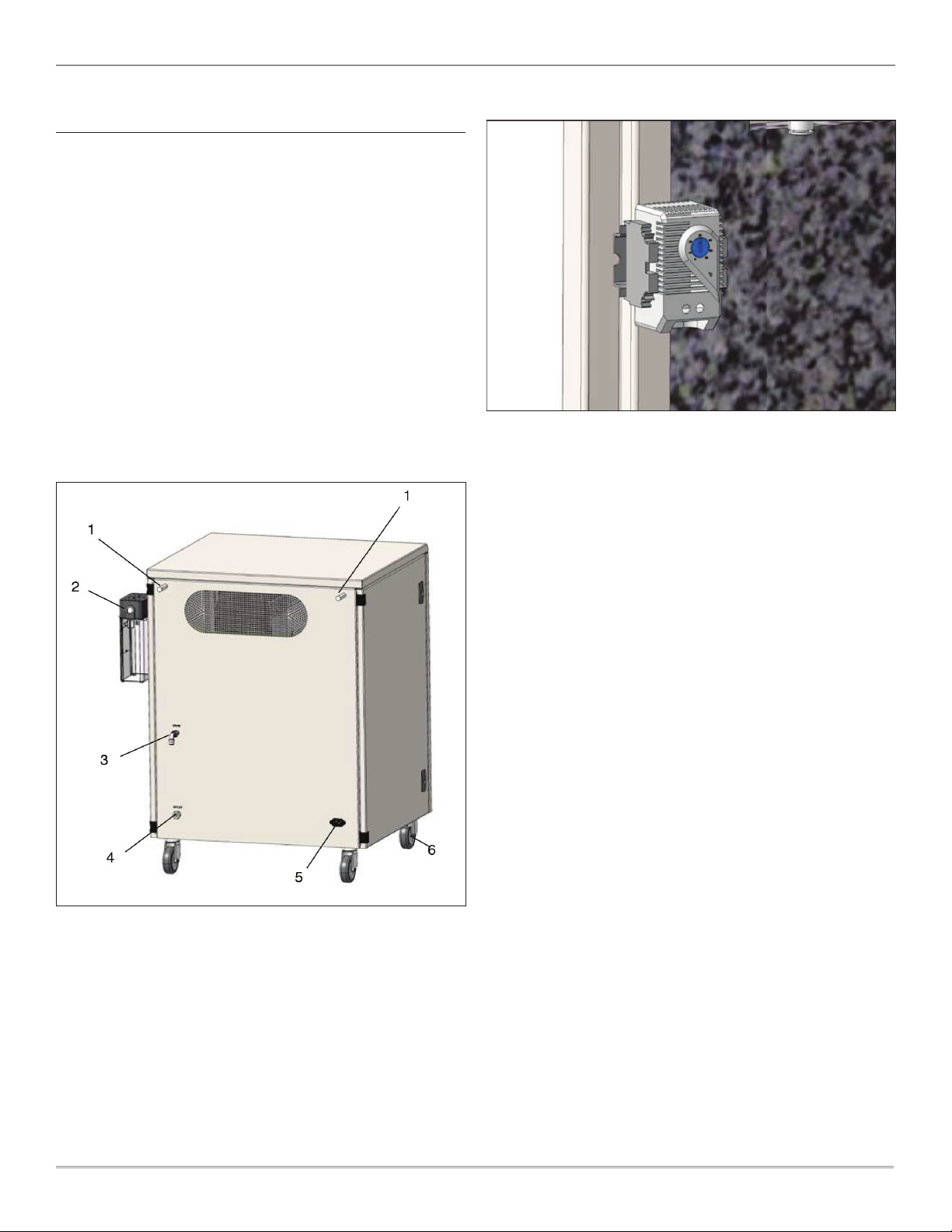
Mount the two distance bolts (1) on the back of the cabinet to ensure
sufficient ventilation.
Installation
• Mount the drain bottle (2) visibly outside the cabinet and mount
the hose at the back of the cabinet (3).
• Connect the cable at the back of the cabinet (5).
• Plug the compressor into a standard outlet switch.
• Connect equipment at the back of the cabinet (4).
• The front wheels are delivered with brakes. Brake the wheels
before starting the compressor (6).
Thermo Switch
The fans are controlled by a Stego thermo switch adjusted to 30°C
from the factory – do not alter this setting. Check that the setting is
correct and adjust if necessary.
The fans will start when the temperature inside the cabinet exceeds
30°C and will run continuously until the temperature drops below
30°C.
5
© 2023, JUN-AIR
We reserve the right to make any alterations which may be due to any technical improvements
Printed in the USA
106R Cabinet Systems User Guide 6190759 (Rev B)
OPERATION
• If the compressor has been stored at an extremely low
temperature, allow it to heat to room temperature before
switching it on.
• The cut-in and cut-out pressure is preset from the factory and
it is normally not necessary to change this. However, if it is
necessary to change the preset settings, the instructions of this
manual shall be followed carefully.
• All AC compressors are designed for 100% duty, but 50%
operation is recommended to prolong the lifetime.
• The fans on the back of the cabinet will start when the
temperature exceeds 30°C. It will run continuously even if the
compressor may have switched of until the temperature is below
30°C again.
• Do not lubricate the oil-less motor with oil, as it will destroy
important components.
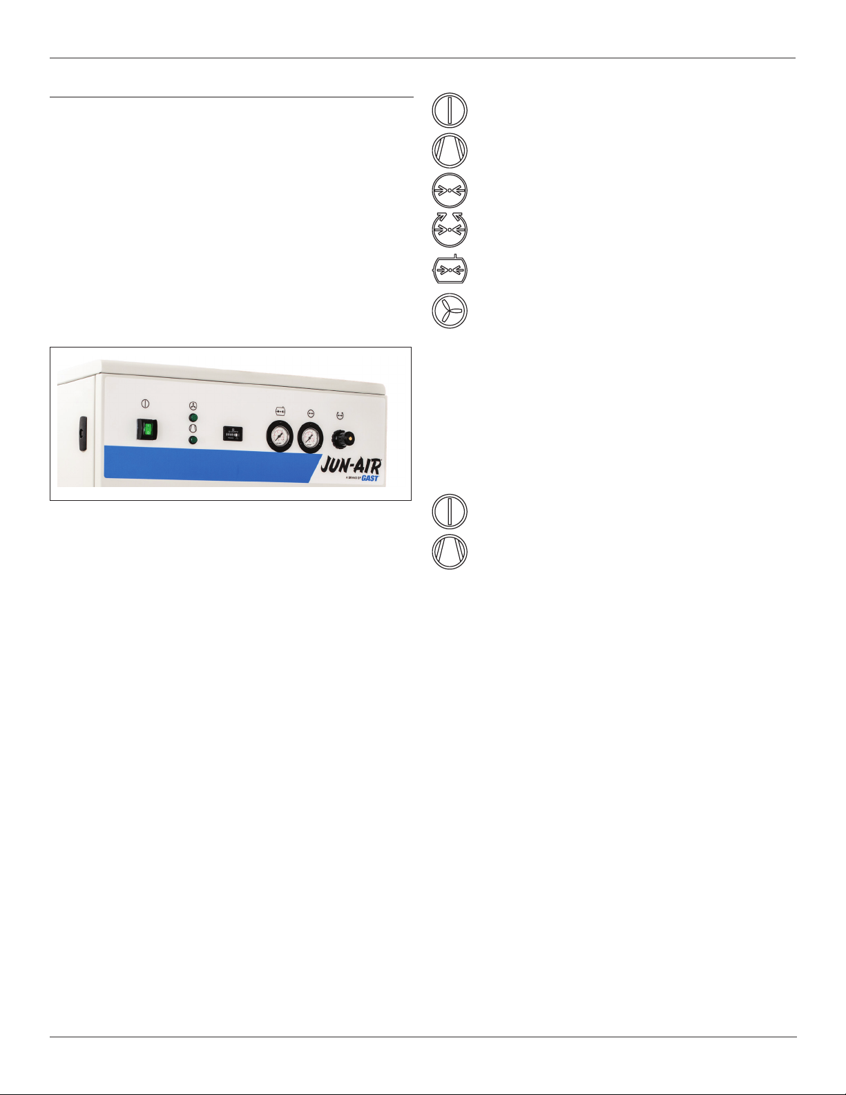
Start
Start the compressor by pressing the green button.
The green lamp for compressor in operation is now
alight.
Read the outlet pressure on the pressure gauge.
Adjust the pressure on the regulator.
Read the receiver pressure on the pressure gauge.
The green lamp is alight when the fans are in operation.
Read on the hour counter the elapsed service time.
If the compressor does not start, there might be pressure in
the receiver. The compressor will automatically start when the
pressure drops.
The compressor will automatically stop when the preset cut-out
pressure is reached.
Stop
Turn off the compressor by pushing the green button.
The green light for compressor in operation switches off.

6
6190759 (Rev B) 106R Cabinet Systems User Guide
© 2023, JUN-AIR
We reserve the right to make any alterations which may be due to any technical improvements
Printed in the USA
MAINTENANCE
To ensure a long lifetime of the compressor, it is important that
inspection and maintenance is carried out regularly as described in
the following.
Read the elapsed operation time on the hour counter.
Opening of cabinet
Turn the four () locks clockwise with a screwdriver or sim. to
open the cabinet.
Preventive maintenance
Activity Weekly Monthly
One a year,
or every
2000 hours
aDrain condensate •
bCheck filter regulator •
cCheck for leaks •
dClean the unit •
eCheck safety valve •
fCheck inlet filter •
gCheck non-return
valve •
hCheck fans •
iCheck dryer •
a) Drain condensate
CAUTION
Risk of Bursting
Open door to access drain assembly.
If drain bottle is installed, empty when necessary. ().
) Drain condensate by opening the manual drain on the receiver.
If mounted with auto drain, condensate will be drained
automatically.
b) Check outlet filter
Check and change the filter and filter element in accordance with
the instructions in ”Installation and maintenance instructions” for
the filter in question.
c) Check for leaks
Check motor, hoses and equipment for leaks. Check the pumping
time.
d) Clean the unit
Clean the unit when needed with a soft, damp cloth. If necessary,
use paraffin to remove adhesions. Dust and dirt prevent cooling.
e) Check safety valve
Check the safety valve with pressure in the receiver. The safety valve
is operated by pulling the ring (1) or turning the screw (2) depending
on the valve type.
f) Check intake filter
Check the intake filter and change it if necessary.
g) Check the non-return valve
Turn off the compressor on the mains switch and pull out the
plug.
Empty the receiver for compressed air by operating the safety
valve. When the receiver is empty, the reading of the pressure
gauge is bar.
Dismount the non-return valve from the receiver.
7
© 2023, JUN-AIR
We reserve the right to make any alterations which may be due to any technical improvements
Printed in the USA
106R Cabinet Systems User Guide 6190759 (Rev B)
Disassemble the non-return valve and remove the O-ring () part
no. from the piston.
Clean the non-return valve.
Mount a new O-ring and re-assemble the non-return valve.
Re-install the non-return valve.
h) Check the fans
Check that the fans at the back of the cabinet work. They
will start when the temperature exceeds °C and will run
continuously until the temperature falls below °C.
i) Check dryer
If a dryer is installed refer to the operating manual for the dryer.
Please note that all service must be carried out by a qualified
person.
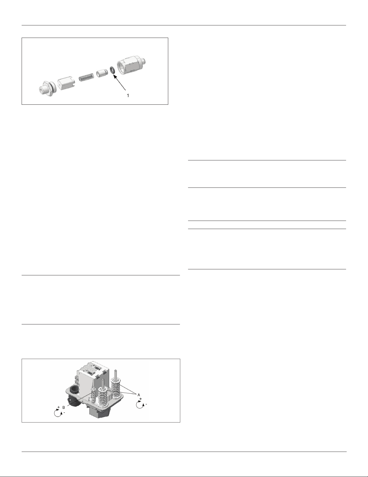
Adjustment of pressure switch
The working presure has ben preset from the factory, and it is
normally not necessary to change this.
However, if it is necessary to change the preset settings, the
instructions mentioned below should be followed carefully.
Warning
The compressor is constructed and approved for a max.
pressure as stated under Technical Specifications - do not
adjust to a higher pressure.
Higher working pressure will reduce the lifetime of the
compressor.
The compressor will stop at max. pressure (stop pressure) and
start again at min. pressure (start pressure). The difference
between max. and min. pressure is the differens pressure.
Unscrew the lid of the pressure switch. Adjust max. pressure
adjusting the two springs marked A (clockwise: higher pressure).
Adjust the two springs identically.
Adjust the differens pressure adjusting the spring marked B
(clockwise: higher differens pressure, start pressure maintained).
Test of pumping time
The pumping time indicates the condition of the compressor.
. Check that there are no leaks in the system.
. Empty the air receiver of compressed air so that the
pressure gauge shows bar.
. Close the filter regulator and check that the drain valve is
closed.
. Start the compressor and note the time it takes until it is
turned off again by the pressure switch. Check that the
pumping time agrees with the technical specifications for
the actual compressor system.
Please note that the pumping time in this manual is given for to
max pressure. Deviations from this result in deviating results.
Important
Always test the pumping time when cold. If the compressor is
warm, the pumping time will be considerably longer.
FAULT FINDING AND REPAIR
Important
Switch off and isolate from electrical supply before removing
any parts from the pump. Empty air receiver of air before
performing any operation on the compressors’ pressure
system.
1. Compressor does not start
a. The air receiver is pressurized. The motor will start when
the pressure has dropped to the preset start pressure.
Empty the receiver.
b. Check that the mains supply agrees with the motor
label.
c. No power from mains. Check fuses and plug.
d. Bad connection or broken cable.
e. The motor is overheated and the thermal protection
has switched it off. When cooled the motor will turn on
automatically. Go to section .
f. The compressor has not been unloaded and there
is back pressure on the piston. Ensure that the
compressor is unloaded each time it stops.
g. The motor is blocked.
h. Defective capacitor.
2. The compressor makes a buzzing sound but does not start
a. Leaky non-return valve. Dismount the pressure pipe and
check if air leaks from the non-return valve. Clean and
replace.
b. The motor is blocked.

8
6190759 (Rev B) 106R Cabinet Systems User Guide
© 2023, JUN-AIR
We reserve the right to make any alterations which may be due to any technical improvements
Printed in the USA
3. The compressor runs but the pressure does not increase
a. Intake filter clogged. Replace.
b. Non-return valve is clocked. Clean or replace.
c. Leaks in fittings, tubes or pneumatic equipment. Check
with soapy water or by letting unit stay over night
disconnected from mains. Pressure drop should not
exceed bar.
d. Check the piston gaskets. Replace if necessary.
e. Defective valve plate. Contact your JUN-AIR distributor.
4. The motor gets very hot
a. The ambient temperature is too high. If the motor is
installed in a cabinet, sufficient ventilation must be
ensured.
b. Leaks in fittings, tubes or pneumatic equipment. Check
with soapy water or by letting unit stay over night
disconnected from mains. Pressure drop should not
exceed bar.
c. The compressor is overloaded.
5. The compressor runs even if no air is tapped
a. Leaks in fittings, tubes or pneumatic equipment. Check
with soapy water or by letting unit stay over night
disconnected from mains. Pressure drop should not
exceed bar.
6. The compressor does not start at min pressure or does not
stop at max pressure.
a. Defective pressure switch. Replace.
PRESSURE VESSEL
Pressure tested at 4-25 litre 24 bar
40-50 litre 18.3 bar
Directions for use
Application Receiver for compressed air
Receiver specifications See name plate
Installation Tubes, etc. must be installed with
suitable materials
Placement
Observe the working temperature of
the receiver
Ensure sufficient room for
inspection and maintenance
The receiver must be kept in a
horizontal position
Corrosion protection
The surface treatment must be
maintained as required
Internal inspection at least every
five years
Drain condensate at least once a
week
Alternation/repair No welding must be made on
pressurized parts
Safety valve
Ensures that PS will not be
exceeded
Never adjust to a higher pressure
than PS
The capacity of the valve must
be calculated in accordance with
the volume of air supplied by the
compressor
PS - Maximum working pressure of
the receiver

9
© 2023, JUN-AIR
We reserve the right to make any alterations which may be due to any technical improvements
Printed in the USA
106R Cabinet Systems User Guide 6190759 (Rev B)
Technical Data & Specifications
Specifications 106R-4M 106R-25M 106R-
25MQ2
2x10⁶R-
40M
2x10⁶R-
40MQ2
Electrical rating volts 120 V 120 V 230 V 120 V 230 V 120 V 230 V 230 V
Tank size liter 4 25 25 40 40
U.S. gallon 1.1 6.6 6.6 10.6 10.6
Weight kg 46 80 84 85 108 106 111
lbs 102 176 186 188 238 234 245
Dimensions
(w x h x d)
mm 49,9 × 42,2 ×
56,9
44,7 × 85,8 ×
56,9 43,7 × 85,8 × 71,7 64 × 85,9 × 67,6
in 17.3 × 16.6 × 22.4 17.6 × 33.8 × 22.4 17.2 × 33.8 × 28.2 25.2 × 33.8 × 26.6
Continuous System
Output Flow @ 8 bar
(116 psi)
LPM 45.3 45.3
40.2 @
50 Hz
48.7 @
60Hz
43
40.2 @
50 Hz
48.7 @
60 Hz
93.5
82.1 @
50 Hz
96.3 @
60 Hz
62.3 @ 50 Hz
72.2 @ 60 Hz
CFM 1.6 1.6
1.4
@50Hz
1.7
@60Hz
1.5
1.4 @
50 Hz
1.7 @
60 Hz
3.3
2.9 @
50 Hz
3.4 @
60 Hz
2.2 @ 50 Hz
2.6 @ 60 Hz
Cut-in Pressure bar 6
psi 87
Cut-out Pressure bar 8
psi 116
Air Filtration mm 5
Safety Relief Valve
Pressure
bar 11
psi 160
Sound Level dB(A) 5 7.4 5 7. 9
55.8 @
50 Hz
57.9 @
60 Hz
76.8
76.2 @
50 Hz
76.2 @
60 Hz
59.8
57.3 @
50 Hz
58.2 @
60 Hz
57.3 @ 50Hz
58.2 @ 60Hz
Operating
Temperature
°C 5 to 40
°F 41 to 104
Operating Relative
Humidity % 20 to 80
Pump Up Time
(0 to cut out)* mm:ss 00:26 02:33
03:07 @
50 Hz
02:39 @
60 Hz
2:32
03:52 @
50 Hz
03:19 @
60 Hz
1:53
02:11 @
50 Hz
01:52 @
60 Hz
02:32 @ 50 Hz
02:08 @ 60 Hz
* at operating temperature
Technical modifications reserved.

10
6190759 (Rev B) 106R Cabinet Systems User Guide
© 2023, JUN-AIR
We reserve the right to make any alterations which may be due to any technical improvements
Printed in the USA
English German French Spanish Dutch Dansk
Voltage Spannung Voltage Voltaje Voltage Spænding
Frequency Frequenz Fréquence Frequencia Frequentie Frekvens
Power Motor HP Moteur CV Motor CV Motor HP Effekt
Displacement Ansaugleistung Débit Aire aspirado Capaciteit Ydelse
Max. pressure Max. Druck Pression de service
max.
Presión de régimen
máx.
Max. druk Max. driftstryk
Max. current Stromverbrauch Consommation Corriente máxima Max. stroom Strømforbrug
Tank size Behältervolumen Volume réservoir Volumen de tanque Tankvolume Beholderstørrelse
Weight Gewicht Poids Peso Gewicht Vægt
Dimensions
(l x w x h)
Abmessungen
(l x b x h)
Dimensions
(l x p x h)
Dimensiones
(l x a x h)
Afmetingen
(l x w x h)
Dimensioner
(l x b x h)
Noise level Schallemissionen Niveau sonore Nivel de ruido Geluidsniveau Lydniveau
Pumping time Pumpzeit Temps de refoule-
ment
Tiempo de bombeo Pomptijd Oppumpningstid
Neutral is required Null-leiter ist er-
forderlich
Neutre nécessaire Neutro necesairo Neutraal noodza-
kelijk
Nul-leder kræves
Available for opera-
tion at a maximum
pressure of 10
barg/145 psig upon
request. Please
note that operation
at higher pressure
will influence the
life time.
Auf Anfrage er-
hältlich bis zu einem
Betriebsdruck
von max. 10 bar.
Höherer Druck hat
Auswirkungen auf
die Lebensdauer.
Kan leveres til max.
driftstryk på 10 bar.
Bemærk at øget
driftstryk reducerer
levetiden.
Displacement is
reduced by approx.
18-20% on units
with dryer (D).
Min. pressure
required to operate
dryer: 6 bar.
Bei Kompressoren
mit Adsorption-
strockner reduziert
sich die effektive
Luftliefermenge um
18-20% (D). Mind-
estarbeitsdruck für
den Lufttrockner
beträgt 6 bar
Le débit est réduit
de 18-20% pour les
unités avec sécheur
d’air (D) Pression
min. 6 bar
Le capacidad se
reduce con 18-20%
para las unidades
con secador de aire
(D)
Bij systemen
met droger is de
capaciteit ca. 18-
20% lager (D). Min.
benodigde druk
voor de droger: 6
bar
Ydelsen reduceres
med ca. 18-20% på
kompressorer med
tørrer (D). Min. tryk
til drift af tørrer: 6
bar
3-phase units are
approx. 100 mm
wider than 1-phase
units
3 phasige Anlagen
ca. 100 mm breiter.
3-fasede anlæg er
ca. 100 mm bredere
end 1-fasede anlæg.
Technical modifica-
tions reserved.
Technische Änder-
ungen vorbehalten
Droits réservés
pour modifications
techniques
Reservamos el
derecho a cambiar
estas especifica-
ciones técnicas sin
previo aviso
Technische wijzigin-
gen voorbehouden
Ret til ændringer
forbeholdes
Translations
11
© 2023, JUN-AIR
We reserve the right to make any alterations which may be due to any technical improvements
Printed in the USA
106R Cabinet Systems User Guide 6190759 (Rev B)
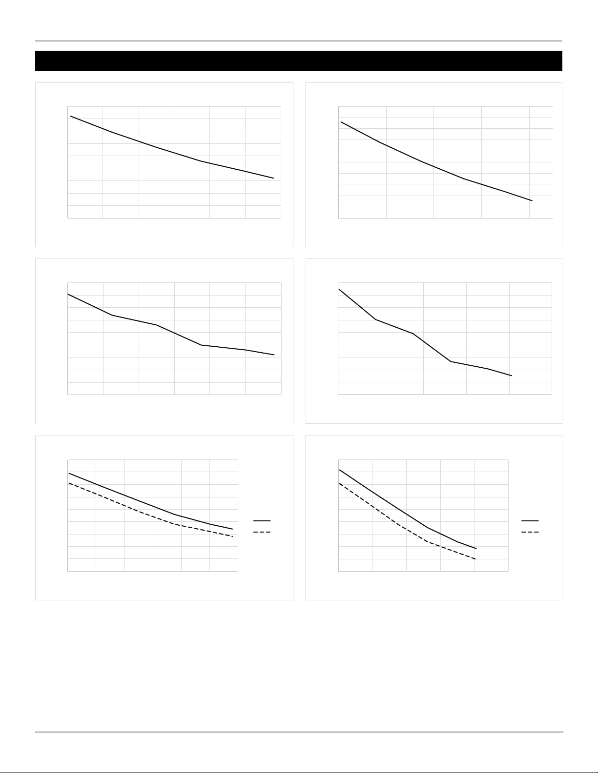
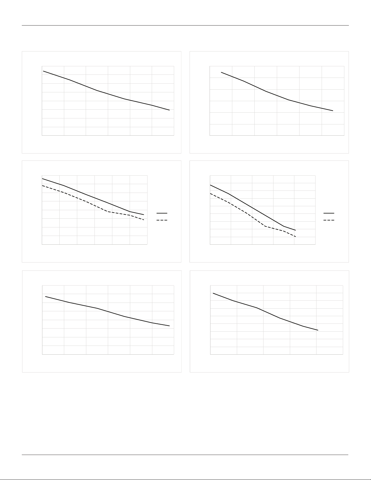
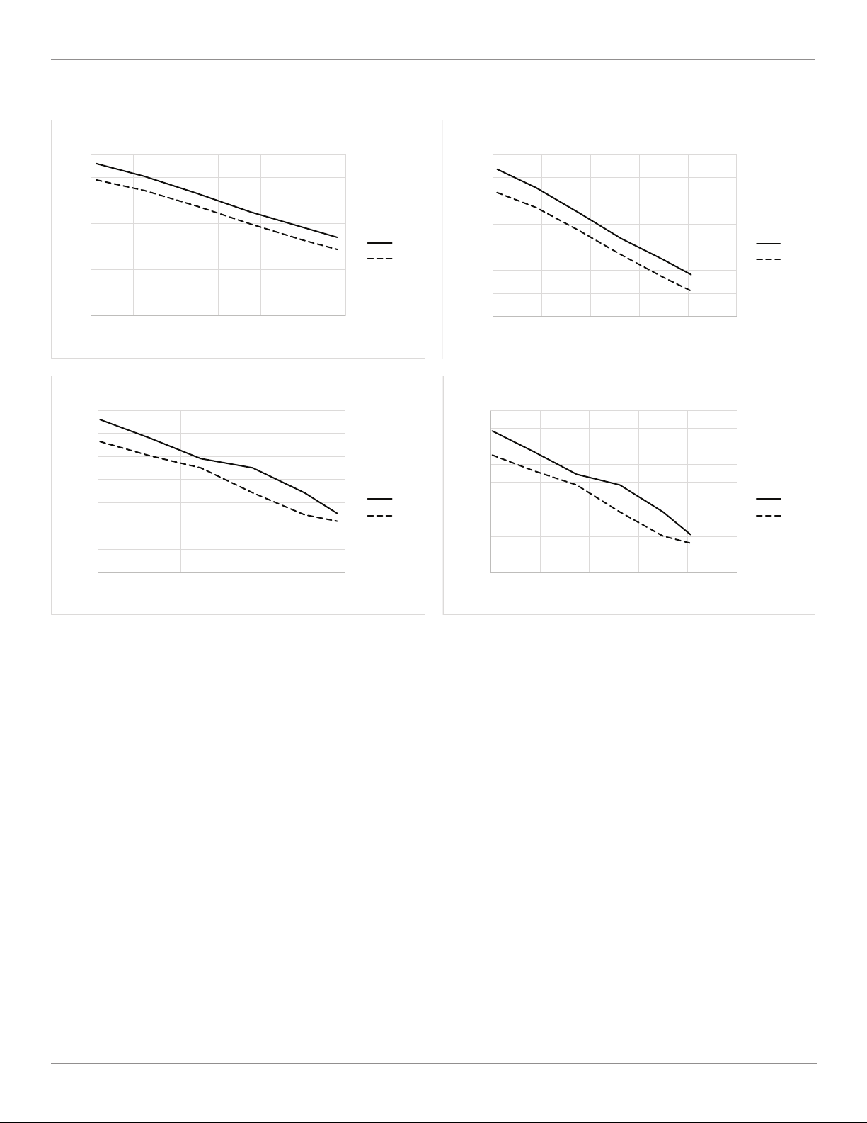
Performance Curves
0.0
0.5
1.0
1.5
2.0
2.5
3.0
3.5
4.0
4.5
020406080100 120
Flow (CFM)
Duty (psi)
106R-4M 120V Air Flow
30
40
50
60
70
80
90
100
110
120
130
02468
Flow (lpm)
Duty (bar)
106R-4M 120V Air Flow
30
40
50
60
70
80
90
100
110
120
130
02468
Flow (lpm)
Duty (bar)
106R-4M 120V Air Flow
0.0
0.5
1.0
1.5
2.0
2.5
3.0
3.5
4.0
4.5
020406080100 120
Flow (CFM)
Duty (psi)
106R-25M 120V Air Flow
30
40
50
60
70
80
90
100
110
120
0246810
Flow (lpm)
Duty (bar)
106R-25M 120V Air Flow
0.0
0.5
1.0
1.5
2.0
2.5
3.0
3.5
4.0
4.5
020406080100 120
Flow (CFM)
Duty (psi)
106R-25M 230V Air Flow
60Hz
50Hz
30
40
50
60
70
80
90
100
110
120
0246810
Flow (lpm)
Duty (bar)
106R-25M 230V Air Flow
60Hz
50Hz
12
6190759 (Rev B) 106R Cabinet Systems User Guide
© 2023, JUN-AIR
We reserve the right to make any alterations which may be due to any technical improvements
Printed in the USA
0.0
0.5
1.0
1.5
2.0
2.5
3.0
3.5
4.0
020406080100 120
Flow (CFM)
Duty (psi)
106R-25MQ2 120V Air Flow
0
20
40
60
80
100
120
0.079979181 1.72368925 3.447378 55.171067756.8947577.99791812
Flow (lpm)
Duty (bar)
106R-25MQ2 120V Air Flow
0.0
0.5
1.0
1.5
2.0
2.5
3.0
3.5
4.0
020406080100 12 0
Flow (CFM)
Duty (psi)
106R-25MQ2 230V Air Flow
60Hz
50Hz
30
40
50
60
70
80
90
100
110
120
0246810
Flow (lpm)
Duty (bar)
106R-25MQ2 230V Air Flow
60Hz
50Hz
0.0
1.0
2.0
3.0
4.0
5.0
6.0
7.0
8.0
020406080100 120
Flow (CFM)
Duty (psi)
2x10⁶R-40M 120V Air Flow
30
50
70
90
110
130
150
170
190
210
0246
81
0
Flow (lpm)
Duty (bar)
2x10⁶R-40M 120V Air Flow
13
© 2023, JUN-AIR
We reserve the right to make any alterations which may be due to any technical improvements
Printed in the USA
106R Cabinet Systems User Guide 6190759 (Rev B)
0
1
2
3
4
5
6
7
020406080100 12 0
Flow (CFM)
Duty (psi)
2x10⁶R-40M 230V Air Flow
60Hz
50Hz
60
80
100
120
140
160
180
200
0246810
Flow (lpm)
Duty (bar)
2x10⁶R-40M 230V Air Flow
60Hz
50Hz
0.0
1.0
2.0
3.0
4.0
5.0
6.0
7.0
020406080100 120
Flow (CFM)
Duty (psi)
2x10⁶R-40MQ2 230V Air Flow
60Hz
50Hz
30
50
70
90
110
130
150
170
190
210
0246810
Flow (lpm)
Duty (bar)
2x10⁶R-40MQ2 230V Air Flow
60Hz
50Hz
14
6190759 (Rev B) 106R Cabinet Systems User Guide
© 2023, JUN-AIR
We reserve the right to make any alterations which may be due to any technical improvements
Printed in the USA
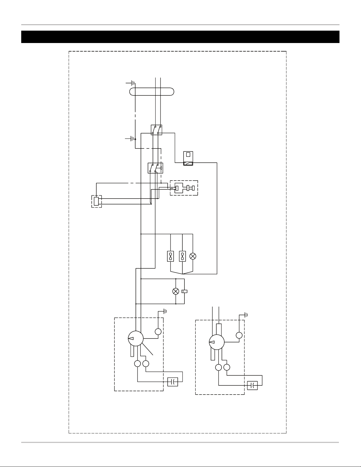
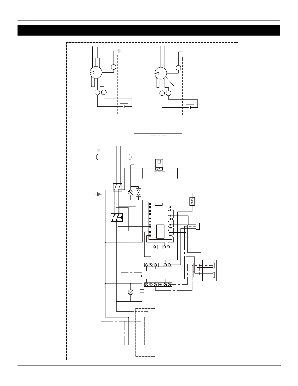
Electrical Drawing Model R-M and R-M
Z
Compressor
Motor
W
X
Ins.
Capacitor
Brown
Green &
Yellow
Red
Black
Or ange
Brown
Compressor Chamber
230V
White
In
out
PRESSURE RELIEF
3*AWG16
Cabinet
PRESSURE SWITCH DPST I/O Switch
t
ADJUSTABLE
THERMO SWITCH
MODELS WITH
AUTOMATIC DRAIN
h
N
L1
Blue
Brown
120V
Compressor Chamber
Compressor
Motor
Capacitor
Z
X
W
Green &
Yellow
Brown
Brown
Red
Orange White
Blue
Black
Brown
Blue
Brown
Blue
Yellow
Brown
Blue
Orange
Pink
Red
Red
Red
Fan
Fan
Hourcounter
Lamp
Lamp
Blue
Blue
Blue
Blue
Blue
Brown
15
© 2023, JUN-AIR
We reserve the right to make any alterations which may be due to any technical improvements
Printed in the USA
106R Cabinet Systems User Guide 6190759 (Rev B)
Electrical Drawing Model R-MQ and xR-MQ
3*AWG16
Cabinet
PRESSURE SWITCH
DPST I/O Switch
h
N
L1
t
ADJUSTABLE
THERMO SWITCH
Blue
Brown
Yellow/Green
BrownBlue
N1
L1
N111213141B1C1D1E
Q1 Q2 Q3 Q4
100-240V AC
SR2B121FU
OUTPUT 4x Relale/8A
Brown
Blue
Brown
BrownBrown BrownBrown
MOTOR PRESSURE
RELIEF
Brown
Red
DRYER
FAN
Blue Brown
Brown
Blue
Blue
Blue
Blue Blue
Yellow
Yellow
FAN
Red
Red
Orange
To Motor or Thermoswitch
Blue
LAMP
HOUR COUNTER
Blue Blue
Brown
Brown
Yellow/Green
TO
MOTOR
Yellow/Green
Blue
Brown
TO
MOTOR
LAMP
2X10⁶R-40MQ2
Brown
Blue
Brown
Blue
White
230V
Compressor Chamber
Brown
Or ange
Black
Red
Green &
Yellow
Brown
Capacitor
Ins.
X
W
Compressor
Motor
Z
Black
Blue
White
Orange
Red
Brown
Brown
Green &
Yellow
W
X
Z
Capacitor
Compressor
Motor
Compressor Chamber
120V

16
6190759 (Rev B) 106R Cabinet Systems User Guide
© 2023, JUN-AIR
We reserve the right to make any alterations which may be due to any technical improvements
Printed in the USA
Electrical Drawing Model xR-M
In
out
PRESSURE RELIEF
3*AWG16
Cabinet
PRESSURE SWITCH DPST I/O Switch
t
ADJUSTABLE
THERMO SWITCH
MODELS WITH
AUTOMATIC DRAIN
MODELS WITH
DRYER
h
N
L1
Brown
BrownBlue
BlueRed
Orange
Blue
Brown
Blue
Brown
Black
BlackBlack
Yellow
WhiteWhite
White
LAMP
LAMP
HOURCOUNTER
FAN
Blue
White
230V
Compressor Chamber
Brown
Orange
Black
Red
Green &
Yellow
Brown
Capacitor
Ins.
X
W
Compressor
Motor
Z
Orange
Black
Red
Green &
Yellow
Brown
Capacitor
Ins.
X
W
Compressor
Motor
Z
Brown
Compressor Chamber
Blue
White
230V
Blue
Black
Blue
White
Orange
Red
Brown
Brown
Green &
Yellow
W
X
Z
Capacitor
Compressor
Motor
Compressor Chamber
120V
N
L1
BlueBrown
Pink
FAN
FAN
Blue
Brown
Brown
Blue
Blue
Blue
Blue
eulBeulB

17
© 2023, JUN-AIR
We reserve the right to make any alterations which may be due to any technical improvements
Printed in the USA
106R Cabinet Systems User Guide 6190759 (Rev B)
Pneumatic Diagram Model R-M
4 Liter Tank
To Drain Bole
Check
Valve
h
Automac
Drain Valve
Regulated
Pressure
Pressure Switch
Tank
Pressure
Pressure
Relief
SAFETY VALVE
5
µm
Filter
COMPRESSOR AIR OUTLET
Compressor
with Motor
Intake Filter

18
6190759 (Rev B) 106R Cabinet Systems User Guide
© 2023, JUN-AIR
We reserve the right to make any alterations which may be due to any technical improvements
Printed in the USA
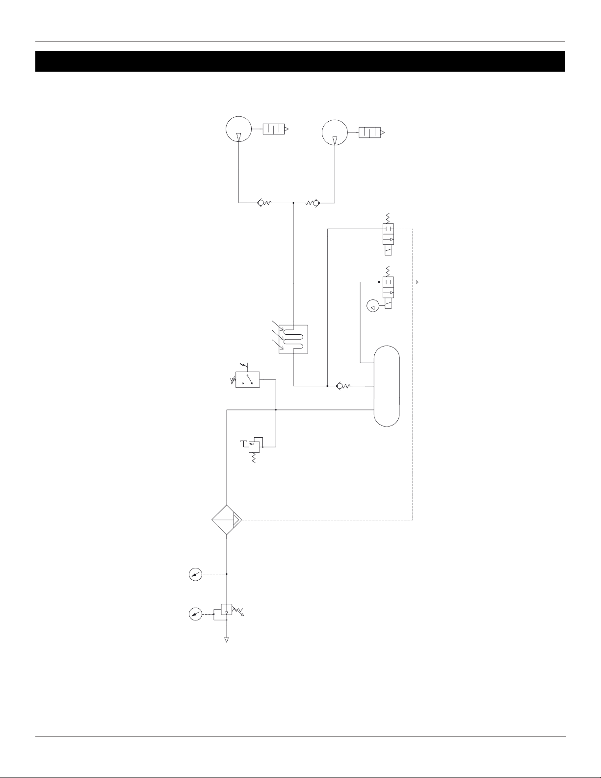
Pneumatic Diagram Model R-M
Intake Filter
Aercooler
25 Liter Tank
To Drain Bole
Check
Valve
h
Tank Purge
Timer Solenoid
h
Regulated
Pressure
Pressure Switch
CUT-IN 6.0 BAR (87 psi)
CUT-OUT 8.0 BAR (116 psi)
Tank
Pressure
Dump
Solenoi
d
Valve
Compressor
with Motor
SAFETY VALVE 12
BAR 177 PSI
5
µm
Filter
COMPRESSOR AIR OUTLE
T
19
© 2023, JUN-AIR
We reserve the right to make any alterations which may be due to any technical improvements
Printed in the USA
106R Cabinet Systems User Guide 6190759 (Rev B)
Pneumatic Diagram Model xR-M
Intake Filter
Aercooler
40 Liter Tank
To Drain Bole
Check
Valve
h
Automac
Drain Valve
Regulated
Pressure
Pressure Switch
Tank
Pressure
Pressure
Relief
Compressor
with Motor
SAFETY VALVE
5
µm
Filter
COMPRESSOR AIR OUTLET
Compressor
with Motor
Intake Filter

20
6190759 (Rev B) 106R Cabinet Systems User Guide
© 2023, JUN-AIR
We reserve the right to make any alterations which may be due to any technical improvements
Printed in the USA
Pneumatic Diagram Models R-MQ & xR-MQ
To Drain Bole
Intake Filter
Aercooler
CO
MPRESSOR AIR
OU
TLET
Tank
Pressure
Regulated
Pressure
Regulated
Pressure
Tank
Pressure
COMPRESSOR AIR
OUTLET
25L
40L
TA
NK
ADSORPTIONDRYER - ADJ50/150/300
Valve
DRYER
Intake Filter
Compressor
Compressor
DRYER
2x10⁶R-40MQ2
Pressure
SwitchSafety
Valve
Pressure
Relief
Safety
Valve
Pressure
Switch
Filter with
Automac Drain
Filter without
Automac Drain
Counter with
Reducer
Non
Return
Valve
Pressure
Relief
Non
Return
Valve
This manual suits for next models
12
Table of contents
Other Gast Air Compressor manuals


Popular Air Compressor manuals by other brands

Rothenberger
Rothenberger ROPULS eDM D Instructions for use

AirCom
AirCom SealAir2K manual

MULTIQUIP
MULTIQUIP DIS185SSI4F installation instructions

Gardner Denver
Gardner Denver INTEGRA EFD99E Operating and service manual

Carlyle
Carlyle 06D Application guide

EINHELL
EINHELL TE-AC 50 Silent Original operating instructions


