GatesAir Intraplex IP Link 100e User manual

IP Link 100e Audio over IP
Card
For FAX Compact Series Transmitter
888-2944-001
Revision A
Oct 2021

Intraplex®IP Link 100e Quick Start Guide v1.0
Page 2of 8
Publication Information
©2021 GatesAir, Inc. . Proprietary and Confidential.
GatesAir considers this document and its contents to be proprietary and confidential.
Except for making a reasonable number of copies for your own internal use, you may
not reproduce this publication, or any part thereof, in any form, by any method, for any
purpose, or in any language other than English without the written consent of GatesAir.
All others uses are illegal.
This publication is designed to assist in the use of the product as it exists on the date of
publication of this manual, and may not reflect the product at the current time or an
unknown time in the future. This publication does not in any way warrant description
accuracy or guarantee the use for the product to which it refers.
GatesAir reserves the right, without notice to make such changes in equipment, design,
specifications, components, or documentation as progress may warrant to improve the
performance of the product.
Trademarks
[Product names and other appropriate trademarks, e.g. Maxiva™, Intraplex® HD
Link™, PowerSmart®, Flexiva™ 3DX®] are trademarks of GatesAir or its subsidiaries.
Microsoft® and Windows® are registered trademarks of Microsoft Corporation. All other
trademarks and trade names are the property of their respective companies.
Contact Information
GatesAir has office locations around the world. For locations and contact information
see: http://www.gatesair.com/contact-us/
Support Contact Information
For support contact information see:
▪
▪

Intraplex®IP Link 100e Quick Start Guide v1.0
Page 3of 8
Intraplex® IP Link 100e Quick Start
Guide
Congratulations on purchasing the Intraplex®IP
Link 100e! This document provides initial setup
instructions.
A) Installation
You may need to install your IP Link
100e in a Flexiva Transmitter if you did
not purchase them together. Otherwise,
you can skip this section and start with
Section B.
1. Remove AC power from Flexiva
Compact Class Transmitter and
transport to an ESD safe
workbench.
2. Remove top cover of transmitter
(Figure 1).
Figure 1. Flexiva Top Cover
3. Locate the modulator board in your
transmitter. This is the large circuit
card pictured in Figure 2.
Figure 2. Flexiva Modulator Board
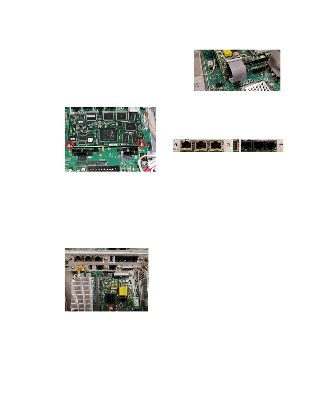
4. From the back of the transmitter
remove the 3 screws securing the
bottom-most knock out panel. Keep
these screws as they will be used in
future steps. Remove the aluminum
panel and set aside (Figure 3).
Figure 3. Remove Rear Panel
5. (If there are no other cards
installed) Install the two standoffs
supplied with the kit as shown in
figure below. The rear of the 100e
card will sit on top of these in the
next step (Figure 4).
Figure 4. Install Standoffs
Without Other Cards
Intraplex®IP Link 100e Quick Start Guide v1.0
Page 4of 8
6. (If other cards are installed) For
those customers with an Orban
processor or Exgine card installed
you will not see empty standoffs.
Remove the two screws shown in
Figure 5 that hold the top card onto
the standoffs below. Install the
supplied standoffs in place of the
screws that were removed. Keep
the screws as they can be used in
future steps.
Figure 5. Install Standoffs With
Other Cards
7. Set the 100e card on top of the new
standoffs. The screws should line up
on top of the posts as well as the
three holes that previously held up
the rear close-up plate. Start all
screws by fingers first and do not
tighten. Once all screws are started,
tighten them down (Figure 6).
Figure 6. Install 100e
8. Install supplied cables as shown
below (Figure 7).
Figure 7. Install Cables
9. Replace top cover and screw it
down.
B) Set Up Network Connection
Figure 8. 100e Back Panel Connections
Connect your IP Link 100e MGMT
interface to the desired network. See the
above picture to identify the interfaces
(Figure 8). Network interfaces can be
configured from the Flexiva web
interface once 100e has been installed
in Flexiva. Alternatively, you can
connect to the MGMT interface on the
default IP (192.168.1.1) and do the
network setup once you are in the 100e
web interface.
C) Access 100e
1. Access the software by typing in the
system’s IP through Chrome or
Firefox on a computer that is
connected to the same network as
the IP Link 100e.
2. The login page will be displayed
whenever IP Link 100e is first
accessed.
D) First Login
The IP Link 100e has a default
administrator account with the ability to
create and manage accounts, view log
and configuration files, and upload
feature keys. To configure user
accounts, you will first need to change
the default admin password and create
an engineer account.
MGMT WAN1 WAN2 USB Audio GPIO Serial
Intraplex®IP Link 100e Quick Start Guide v1.0
Page 5of 8
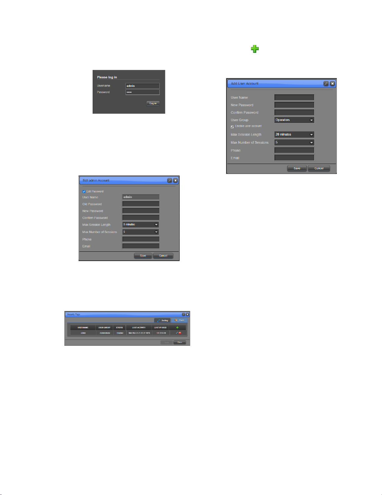
1. After the page loads, the 100e login
page appears (Figure 9).
Figure 9. Login Page
2. Login with the default credentials.
“admin” for Username and
Password.
3. Click Log in.
4. Click OK in the pop-up to change
the default password (Figure 10).
Figure 10. Edit Admin Account
Form
5. Now you can access the Users
page by hovering over
Administration on the left and
clicking Users (Figure 11).
Figure 11. Users Page
6. Click to add a user to the
system. The Add User Account
window appears (Figure 12).
Figure 12. Add User Account
Window
7. Type the User Name for the
account (case sensitive).
8. Enter a password for the user in
New Password and the same
password in Confirm Password
(case sensitive and minimum of
eight characters).
9. For User Group, select “Engineers”
from the dropdown.
NOTE: Engineer accounts can configure the
system while Operators are only able to view
status.
10. Ensure the Enable user account
check box is selected.
11. Make any other changes to the form
as desired.
12. Click Save. The new user now
appears in the Users table.
13. Click Sign out at the top right of the
page.
E) Upgrade Firmware
1. To access the Firmware Manager
(Figure 13), click the Upgrade
Firmware option under the
Administration section on the side
bar menu.
2. Click Upload, then Browse to
select the software package to be
installed, and then Upload again to
load the package onto the system.
3. Click Activate and set the
Firmware Role to “Primary”.

Intraplex®IP Link 100e Quick Start Guide v1.0
Page 6of 8
4. Click OK to reset the system and
load the IP Link 100e Software.
Figure 13. Firmware Manager
F) Configure the Network Interfaces
1. Type the Username and Password
of the Engineer account you just
created.
2. Click Log in. The IP Link 100e
home page appears (Figure 14).
Figure 14. Home Page
3. On the IP Link 100e home page, click
Network Interfaces on the Network
tab. The Networking page appears
(Figure 15).
Figure 15. Networking Settings
4. Click on the active network interface
to bring up its settings.
5. Either enable DHCP or disable
DHCP to set a static IP Address
and Subnet Mask for the connected
network.
6. Click Apply.
7. Enter the newly applied IP address
into the browser’s address bar (as in
Section B, Step 2) and press enter.
Note: If the system is assigned a
new network address, you may also
need to reconfigure your PC to
regain access.
G)Define a Static Route
If you are using IP Link 100e on a
different subnet, perform these steps to
define a static route:
1. Under the Networking tab, click the
Forwarding Table. The
Forwarding Table page appears
(Figure 16).
Figure 16. Forwarding Table
2. Configure the Destination,
Netmask, and Gateway.
3. Click Apply.
H) Configure Channels
To configure the channel settings, click
the on the top right of the channel.
This will show the Channel page
(Figure 17). Here you will find tabs for
Intraplex®IP Link 100e Quick Start Guide v1.0
Page 7of 8
the input and output channel settings.
You can change the sample rate and
channel sources.
Figure 17. Channel Settings Page
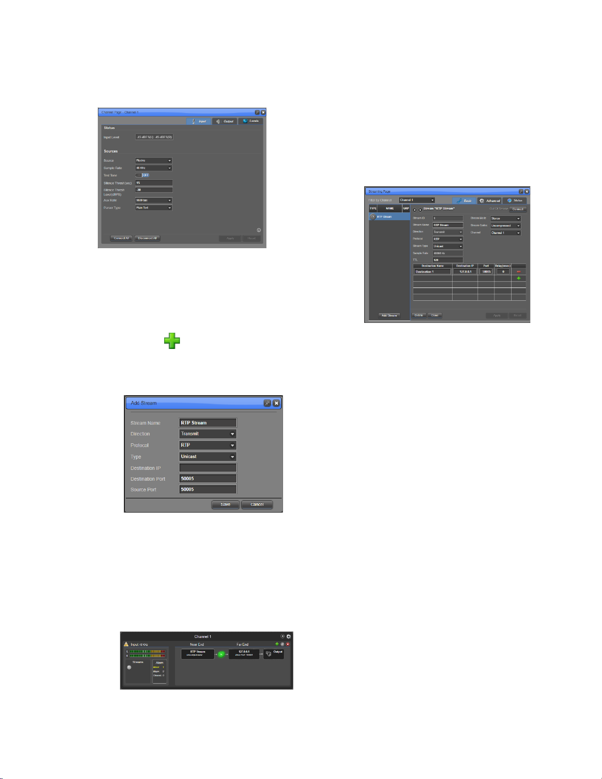
I) Set Up RTP Unicast Streams
To create an RTP stream and set
stream parameters, complete the
following steps:
1. Click the in the top right of the
input or output section of the
channel to bring up the Add Stream
page (Figure 18).
Figure 18. Stream Creation
Window
2. For transmit streams, enter the
Destination IP address. For receive
streams, no fields require any
changes.
3. Click Save and the stream will be
displayed on the channel on the
IPLink Home page (Figure 19).
Figure 19. Channel with Stream
4. To begin streaming, right-click the
stream and click Connect. The
stream will turn green if connected
to a receiving stream and working
properly.
5. To view or change the stream’s
settings, click on the stream and the
Streaming window appears (Figure
20).
Figure 20. Stream Settings
Repeat the above steps to setup
additional RTP streams.

Intraplex®IP Link 100e Quick Start Guide v1.0
Page 8of 8
J) I/O Specification
1. AES3 Audio Pin Assignments
StudioHub pinout for RJ-45
connector
2. GPIO Pin Assignments
Contact Inputs:
•TTL (Transistor-Transistor-
Logic) compatible OR closure to
ground
•Inputs are active low. (TTL low
or shorting to ground causes
assertion.)
•Max voltage input = 5 V
Contact Outputs:
•Max Voltage = 350 V
•Max Current = 120 mA
•Max On Resistance = 35 Ohms
(when active)
Output Contact State:
•Power Off –Hi-Z
•Initial Power On –Hi-Z
•Normal –Hi-Z
•Alarm or Assert –Low-Z
3. Serial Pin Assignments
K) Additional Help
If you have questions or any difficulties
installing or configuring your Ascent
system, please call or send non-
emergency email to GatesAir Customer
Support:
•U.S., Canada, and Latin America:
•1-217-222-8200 or
•Europe, Middle East and Africa:
tsupport.europe@gatesair.com
•Asia and Pacific Rim:
tsupport.asia@gatesair.com
Not Used
Not Used
Table of contents


