TONO Theta-9000e User manual

Θ- 9000E
COMMUNICATIONS TERMINAL

TABLE OF CONTENTS
1. FEATURES & PRECAUTIONS
1-1 Features ...................................................................... 1
1-2 Precautions ................................................................. 7
2. INSTALLATION
2-1 Keyboard Introduction .................................................. 8
2-2 Rear Apron Connections ............................................... 9
2-3 Jac and Connector on CPU Board ................................. 10
2-4 Mode and Function Programming .................................. 10
2-5 Outline of Screen ......................................................... 10
3. CONNECTION
3-1 Power Supply .............................................................. 13
3-2 Video Monitor .............................................................. 13
3-3 Transceiver .................................................................. 13
3-4 Oscilloscope ................................................................ 13
3-5 Printer ........................................................................ 14
4. SET UP
4-1 Preliminary Setting ....................................................... 16
4-2 Procedure to Power-up the Equipment ........................... 16
5. OPERATION
5-1 CW Mode (MORSE) ...................................................... 17
5-2 RTTY Mode (BAUDOT) .................................................. 22
5-3 ASCII Mode ................................................................. 27
6. DATA TRANSMISSION
6-1 Classification of the Data Transmission .......................... 30
6-2 Buffer Transmission ...................................................... 30
6-3 Channel Memory Transmission ...................................... 30
6-4 Screen Transmission ("SEND" Function) ......................... 33
6-5 Echo-Bac Transmission ............................................... 33
6-6 Test Message Transmission .......................................... 34
7. VARIOUS FUNCTIONS
7-1 Split-Screen Mode ........................................................ 35
7-2 Graphic Mode .............................................................. 35
7-3 Control Code Output .................................................... 37
7-4 Selective Calling System ............................................... 37
7-5 Full Duplex Mode ......................................................... 39
8. WORD PROCESSOR MODE
8-1 Introduction ................................................................ 43
8-2 Various Functions ......................................................... 46
8-3 Channel Memory .......................................................... 53
8-4 Application .................................................................. 54
9. INTRODUCTION TO ALL THE FUNCTION EYS
9-1 MORSE, BAUDOT and ASCII Mode ................................ 57
9-2 Word Processor Mode ................................................... 60

10. APPLICATION
10-1 Connection to a Cassette Tape Recorder ........................ 63
10-2 Connection to the Equipment with RS232C Input/Output . 63
11. MAINTENANCE
11-1 Battery Replacement for the Battery-Bac ed-Up Memory . 63
11-2 Fuse Replacement ........................................................ 63
11-3 Light Pen ..................................................................... 63
Code Tables ................................................................................... 64
Input/Output Circuit ..................................................................... 67
Block Diagram ............................................................................... 68

1
1. FEATURES & PRECAUTIONS
1-1 Features
1. Communications Terminal
As a result of the most up-to-date microprocessor technology, just one piece of equipment can
accomplish complete automatic send/receive of Morse code (CW), Baudot code (RTTY) and AS-
CII code (RTTY & KCS). By using a light pen, it can also handle send/receive of graphic pat-
terns and characters freely.
2. Word Processor Function
Helps with easy generation of documents or letters. With cassette tape recorder storage, the
document can be stored and modified.
3. Selective Calling System
With a eyboard command, SELCAL mode becomes active. Upon receipt of the signal corre-
sponding to your own "SELCAL Characters" (stored in CMOS-Battery-Bac -Up memory), the Θ-
9000E begins to receive the message. And your own "End of Text" will terminate the reception.
Also capable of calling up the specified distant station.
4. Two Display Format and Large Capacity Display Memory
Provides two different display format: 80 characters × 24 lines and 40 characters × 24 lines.
Manually changeable with the eyboard command. Display memory covers up to 14,000 char-
acters. The scroll feature enables to display of all the characters.
5. Graphic Function
Using the accessory light pen, graphic pattern can be drawn on the screen and easily transmit-
ted and received.
6. Full Duplex Function
You may select full duplex mode when the Θ-9000E is used for ASCII mode. Capable of using
as CRT terminal by RS232C serial interface. You can handle up to 9600 baud in send/receive.
7. Built-in Demodulator for High Performance
Three-step shift selects either 170 Hz, 425 Hz or 850 Hz shift with a manual fine tune control
of the space channel for odd shifts. HIGH (Mar Frequency 2125 Hz) / LOW (Mar Frequency
1275 Hz) tone pairs available. Mar only or Space only copy capability for selective fading.
8. Crystal Controlled AFSK Modulator
A transceiver without direct FSK inputs can transmit in RTTY mode by utilizing the high stability
crystal-controlled modulator, controlled by the microprocessor.
9. Optoisolator CW, FSK eyer built in
Very high-voltage, high-current optoisolator eyer is provided for CW, FSK eying.

2
10. Automatic Transmit/Receive
The transmit/receive switch is controlled by the microprocessor. Built-in remote control ey
function automatically controls the transmit/receive circuitry of the transceiver. manual opera-
tion is also available.
11. Convenient ASCII Key Arrangement
The eyboard layout is ASCII arrangement with function eys. Automatic insertion of LTR/FIG
code.
12. Two Modes in ASCII
In ASCII, both KCS (Kansas City Standard) and RTTY mode tone sets are available.
13. Battery-Bac -Up Memory
Data in the battery-bac -up memory, covering 256 characters × 7 channels, is retained even
when the external power source is removed. Channel 6 is divided into 16 subsections contain-
ing 32 characters, any of which may be used individually. Messages can be repeated 1–9 times
from a eyboard command and any channel can read out continuously. You can store mes-
sages into any channel while receiving.
14. Anti-Noise Circuit
Well designed anti-noise circuit prevents garbled message in the absence of signal.
15. Screen Display Type-Ahead Buffer Memory
A 3120-character-buffer-memory is displayed on the lower part on the screen. The characters
move to the left erasing one by one as soon as they are transmitted. The operator is free to
prepare messages while another document is received.
16. Function Display System
Each parameter of operation (mode, channel number, speed and so on) is displayed on the
screen.
17. "SEND" Function
Allows to send the transmitted text displayed on the screen, including the data stored in every
channel of the Battery-bac -up memory with an instruction from the eyboard. It is possible to
interrupt the transmission and resume it.
18. Split Screen
With a eyboard command, the same screen format can be divided in two; the upper half for
receive and the lower for transmit, While receiving, you can compose text for transmission in
the Buffer Memory with the Pre-load function, which is to be ta en over by the SEND function.
19. Composite Video Signal Output
Composite Video Signal Output is provided for Video monitor display.

3
20. Printer Interface
Centronics Parallel Compatible interface enables easy connection of a low-cost dot-matrix print-
er for hard copies.
21. Wide range of transmitting and receiving speeds
10 communications speed for transmitting (with AUTOTRACK on receive) in Morse Code and 14
communication speeds with Fine Adjustments for transmitting and receiving in Baudot and AS-
CII. The multiple speed feature ma es the Θ-9000E ideal for amateur, business and commer-
cial use.
22. Pre-load function
The Buffer Memory can store the messages written from the eyboard instead of sending them
immediately. The stored messages can then be sent with a eyboard command.
23. "RUB-OUT" function
You can correct mista es while writing messages in the Buffer Memory and misspellings can be
erased while the information is still in the Buffer Memory.
24. Automatic CR/LF
While transmitting, CR/LF is automatically sent every 64, 72 or 80 characters.
25. WORD MODE operation
Characters can be transmitted in word groupings from the Buffer Memory. Keyboard-Selctable.
26. LINE MODE operation
Characters can be transmitted in line groupings from the Buffer Memory. Keyboard-Selectable.
27. WORD-WRAP-AROUND
In receive mode, WORD-WRAP-AROUND prevents the last word on a line from becoming split
in two and provides you a readable screen.
28. Automatic Idle Signal Insertion
In RTTY mode, idle signal can be automatically inserted in a pause of transmitting.
29. "ECHO" function
With a eyboard instruction, received data can be read and resent at the same time. This func-
tion enables the cassette tape recorder to be used as the bac -up memory and a system can
be created as effective as paper tape storage.
30. Cursor Control function
Full cursor control (up/down-left/right) is available from the eyboard.
31. Test Message function
Two built-in test messages, "RY" and "QBF" are eyboard selectable.

4
32. CW Identification function
In RTTY (Baudot & ASCII) mode, eyboard-controlled CW identification is available if required.
33. MARK-AND-BREAK (SPACE-AND-BREAK) system
Mar only or Space only copy capability for selective fading.
34. Variable CW weights
For CW transmission, weights (ratio of dot to dash) can be changed within the range of 1:3 to
1:6 in ten steps.
35. Audio Monitor Circuit
A built-in audio monitor circuit with an automatic transmit/receive switch enables chec ing of
the transmitting and receiving states. In receiving mode, it is possible to monitor the output of
the mar channel, the space channel and incoming audio from AGC amplifier prior to the chan-
nel filters.
36. CW practice function
The Θ-9000E reads data from the hand ey and displays the characters on the screen. CW ey-
ing output circuit wor s according to the ey operation.
37. CW Random Generator
Output of random CW signal can be used as CW copy practice.
38. Cross-hatch chec ing output terminal
The oscilloscope may be connected to display the traditional cross-hatch tuning indicator. This
supplements the tuning LEDs and audio monitor provided in the system.

5
SPECIFICATIONS
1. Code
Morse Code (CW), Baudot Code (RTTY) and ASCII (RTTY & KCS)
2. Characters
Alphabet, Figures, Symbol and Special Characters
3. Speed
Morse: Receiving 5–50 Words/Minute (Automatic Trac )
Transmitting 5–50 Words/Minute (Weight 1:3 ~ 1:6)
Baudot/ASCII: 45.45, 50, 56.88, 74.2, 100, 110, 150, 200, 300, 600, 1200, 2400,
4800, 9600 Baud
NOTE:Details are mentioned in 2-1. 8.
4. Input
AF Input Impedance: CW, RTTY and ASCII: 500 ohms
KCS Input Impedance: 500 Ohms
TTL Level Input: Common to CW, RTTY and ASCII
RS232C Input: Common to CW, RTTY and ASCII
5. AF Frequency
MORSE: 830 Hz
RTTY (Baudot/ASCII): Mar 1275 HZ (Low-Tone), 2125 Hz (High-Tone)
Shift 170 Hz, 425 Hz, 850 Hz + Fine Tuning
KCS: Mar 2400 Hz
Space 1200 Hz
6. Output
Keying Output: CW 80 mA, 200 V (Optoisolator)
FSK 80 mA, 200 V (Optoisolator)
REMOTE 200 mA, 100 V (Optoisolator)
PTT 100 mA, 100 V (Optoisolator)
AFSK Output Impedance:500 ohms (Common to CW, RTTY and ASCII)
RS232C Output: Common to CW, RTTY and ASCII
7. AFSK Output Frequency
MORSE: 830 Hz
RTTY (Baudot/ASCII) Mar 1275 Hz (Low-Tone), 2125 Hz (High-Tone)
Shift 170 Hz, 425 Hz, 850 Hz + Fine Tuning
KCS Mar 2400 Hz
Space 1200 Hz
8. Display Output
Composite Video Signal Output Impedance: 75 ohms

6
9. Interface for Printer
Centronics Compatible Parallel Interface
10. Number of Characters Displayed
Screen format (Keyboard-selectable): 80 characters × 24 lines = 1920 characters
40 characters × 24 lines = 950 characters
11. Battery-bac -up Memory: 256 characters × 7 channels
12. Buffer memory: 3120 characters
13. Output Impedance for Oscilloscope: 200 Ω
14. AF Output: 150 mW @ 8 ohms
15. Power Supply Requirement: 12 VDC, 1.3 A
16. Dimension: 415 mm × 245 mm × 45 mm ~ 78 mm
17. Accessories
Instruction Manual 1×
Pin Plug 13×
Fuse 1×
Coaxial Cable 4 m
Light Pen 1×
3P Connector 1×
The specifications are subject to change without prior notice.

7
1-2 Precautions
1. You should plan to read this OPERATOR'S MANUAL thoroughly to become familiar with your Θ-
9000E.
2. Before ma ing connection to a transceiver, practice is recommended with a CRT display.
3. Adjust for minimum SWR between the transceiver and antenna as follows:
OUTPUT SWR
< 10 W Maximum 1.5
10 W ··· 100 W Maximum 1.3
100 W ··· 500 W Maximum 1.1
Table 1 SWR Adjustment
4. Be sure that the connection to the input circuits and output circuits are appropriate. Input sig-
nal and load should be within the range mentioned in the Specifications.
5. Voltage of DC power supply should be within the range of DC 11 V ~ 14 V.
6. DC power supply for the Θ-9000E should not be connected to other equipment if any interac-
tion is noticed.
7. It is suggested that the Θ-9000E is put at a well-ventilated dry place not exposed to the direct
sun with special care for intense heat.
8. Notice the maximum speed as follows:
In full duplex mode, the available speed is up to 9600 baud and in RTTY modem, up to 150
baud. When you connect to the cassette tape recorder in KCS mode, the maximum baud rate
is variable according to its characteristic. In good condition, you can handle up to 1200 baud.
Other modes are usually up o 9600 baud.
9. In order to prevent the possibility of receiver interference from the microprocessor cloc , it is
recommended that the receiving antenna not be adjacent to the Θ-9000E terminal. The trans-
mitting antenna should be well matched and also should not be located adjacent to the termi-
nal to prevent R.F. interference to the logic and video generating circuits of the unit. This ter-
minal is well bypassed and is designed in a metal enclosure to minimize any interference prob-
lem.
New Federal Communications Commission (Part 15) regulations require that the following cau-
tion notice be published:
Warning: This equipment generates, uses and can radiate radio frequency energy and if not
installed and used in accordance with the instructions manual, may cause interference to radio
communications. As temporarily permitted by regulation, it has not been tested for compliance
with the limits for Class A computing devices pursuant to Subpart J of Part 15 of the FCC rules
which are designed to provide reasonable protection against such interference. Operation of
this equipment in a residential area is li ely to cause interference in which case the user at his
own expense will be required to ta e whatever measures may required to correct the interfer-
ence.
8
2. INSTALLATION
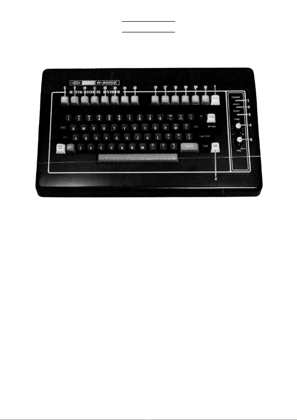
2-1 eyboard Introduction
This section will assist you in becoming familiar with the eyboard controls.
1. POWER LED: indicates power is on.
2. SPACE LED: indicates tuning of the space filter.
3. MARK LED: indicates tuning of the mar filter.
4. FINE TUNING: Fine adjustment of the shift width while receiving BAUDOT RTTY or ASCII
RTTY.
5. VOL: controls the volume of the monitor spea er.
6. LP: This is used for Graphic mode (using light pen).
7. RESET: initializes the microprocessor.
8 – 21: Function Keys - - - Refer to page 57.
9
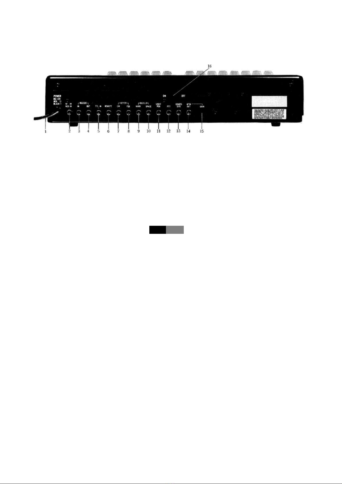
2-2 Rear Apron Connections
This section will introduce you to the rear apron connections on this terminal. Refer to Fi-
gure 2 for the legend of the rear apron.
1. POWER SUPPLY CORD:
12 V DC. Red is positive, blac is GND.
2. AF IN: This is an audio input from EARPHONE terminal of the tape recorder or
EXT SP terminal of the transceiver.
3. RS232C IN: Connects to the serial input of RS232C level.
4. RS232C OUT: Connects to the serial output of RS232C level.
5. TTL IN: This is an input accepting TTL LEVEL of non-modulated signals in CW,
BAUDOT or ASCII.
6. REMOTE: Activates or deactivates the remote-control jac for external equipment.
When you are called up in SEL-CAL mode, the REMOTE line becomes active.
End of SEL-CAL releases this function automatically.
With the eystro e ESC &·6, this jac can be turned ON/OFF regardless
of the SEL-CAL mode.
7. CW: ┐
8. FSK: ┘Connects to the eying terminal of the transceiver in CW or RTTY mode. Out-
puts to collector of optoisolator.
NOTE CW: When in Normal position, this jac is ON in RTTY SPACE or CW
MARK and OFF in RTTY MARK or CW SPACE.
FSK: When in Normal position, this jac is ON in RTTY MARK or CW
SPACE and OFF in RTTY SPACE or CW MARK.
9. MARK: Connects to the Oscilloscope for MARK output of cross hatch.
10. SPACE: Connects to the Oscilloscope for SPACE output of cross hatch.
11. LIGHT PEN: Connects to the accessory light pen when using the Graphic (light pen)
mode.
12. PTT: Connects to the PTT terminal of the transceiver for remote control.
13. COMPOSITE; Feeds to a video monitor.
14. AFSK OUT: This is an audio output from the AFSK generator and may be used to feed
the AUDIO INPUT of a tape recorder or a transceiver.
15. GAIN: Adjusts the output level of the AFSK output jac s.
16. Power Switch

10
2-3 Jack and Connector on CPU Board
On CPU board, you may find the earphone jac and 3P connector (used for full duplex
mode). Follow the procedure below:
(1) Remove two M4 screws on rear panel
and two M4 screws on the bottom.
(2) Connect the earphone jac or 3P
connector if necessary.
2-4 Mode and Function Programming
Modes and functions are set according to instructions from eyboard. Press ESC M so
that the state of MODE, TONE, TYPING MODE, AUDIO, CR/LF AUTOMATIC INSERTION,
SPEED, INPUT or SENSE is retained even if the power is removed. When the power is ap-
plied again, the microprocessor is reset to the same state as one just before the power was
removed. Press ESC ?·/ to initialize the unit. Notice nothing changes on your screen un-
less the power is removed or [ RESET ] is pressed.
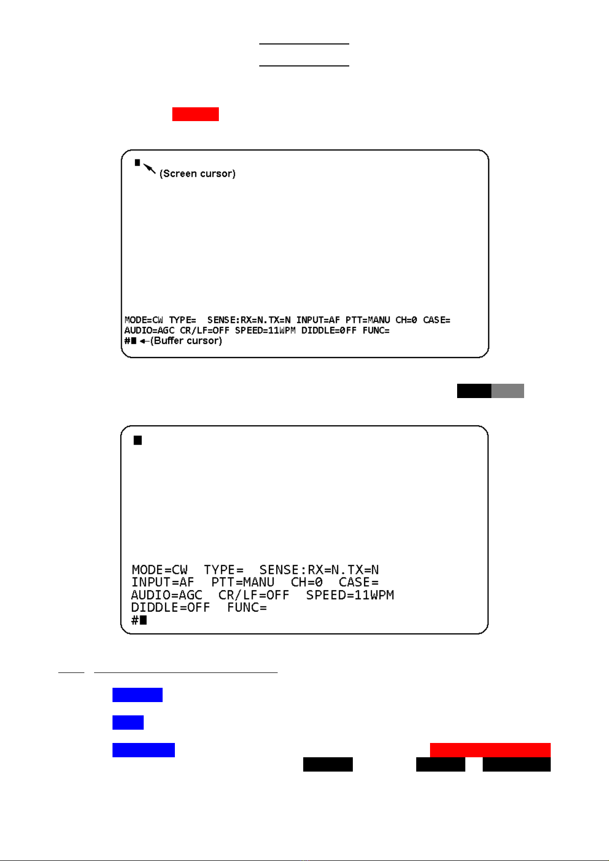
2-5 Outline of Screen
2-5-1 Screen format
(1) 80 × 24 Screen Format
One Screen Format contains 80 characters × 24 lines (1920 characters).
Figure 3-1 80 × 24 Screen Format
* The Send/Receive Screen includes 134 lines (10,720 char.)
* The Buffer Memory Screen includes 39 lines (3,120 char.)

11
(2) 40 × 24 Screen Format
One Screen format contains 40 characters × 24 lines (960 characters).
Figure 3-2 40 × 24 Screen Format
* The Send/Receive Screen includes 268 lines (10,720 char.)
* The Buffer Memory Screen includes 78 lines (3,120 char.)
2-5-2 Screen format in Graphic Mode
Screen Format in Graphic mode using a light pen is a display matrix 80 elements wide by
72 elements high = 5,760 elements.
Figure 4 Screen Format in Graphic Mode

12
2-5-3 Screen format in Split Screen Mode
(1) 80 × 24 Screen Format
Figure 5-1 80 × 24 Screen Format in Split Screen Mode
(2) 40 × 24 Screen Format
Figure 5-2 40 × 24 Screen Format in Split Screen Mode

13
3. CONNECTION
3-1 Power Supply
Before connecting power lead to your DC power supply, ma e sure the voltage is within the
range of DC 11 -- 14 V.
3-2 Video Monitor
Solder an ancillary coaxial cable and a pin plug as shown in FIG. 6, and connect the pin
plug to COMPOSITE jac of the Θ-9000E.
Figure 6 How to solder coaxial cable to pin plug
3-3 Transceiver
Adjust the SWR as shown in Table 1 (page 7) to assure normal operation. For connections,
refer to FIG. 8
3-4 Oscilloscope
The output impedance for OSCILLO (MARK, SPACE) is 200 Ω (maximum amplitude is 3.5
Vpp approx.). Use an oscilloscope whose input impedance is over 1 MΩ.

14
3-5 Printer
Connector CN1 on the CPU board is a connector for a printer. Each pin drives five standard
TTL loads. Avoid overload.
_____
(1) When READY is set LOW, Timing of DATA for printer is as follows:
Figure 7. Timing of data for printer
_____
When READY is set HIGH, the port for printer holds the previous data.
(2) A printer with Centronics Compatible interface can be connected directly to the
Θ-9000E.
(3) Refer to FIG. 19 for Pin Connections.
15
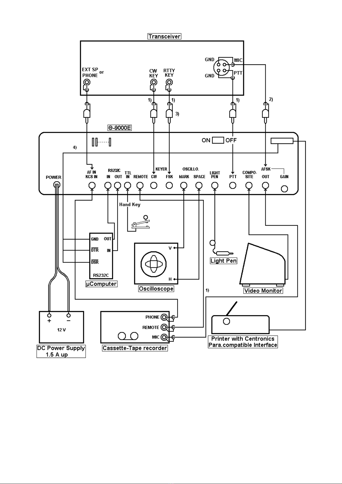
Figure 8 Connections to the peripheral equipment
NOTES:
1) Chec the polarity first with a meter. Ma e sure the center pin in the plug always has the
highest voltage.
2) Connect to the Θ-9000E when used with AFSK function. No need to use for FSK function.
3) Connect to the Θ-9000E when used with FSK function. No need to use for AFSK function.
4) Connect to the internal CPU board with accessory 3P connector.

16
4. SET UP
4-1 Preliminary Setting
Θ-9000E
FRONT PANEL VOL Adjust the volume properly
FINE Medium
REAR PANEL GAIN Medium
Power supply SW OFF
DC Power Supply
Power Supply SW OFF
Transceiver
MODE SW Same mode as the Θ-9000E; RTTY or LSB when using the AFSK function
Power Supply SW OFF
AF VOL Adjust the volume so that the audio input level to the Θ-9000E is set to 0.1 to
1 Vpp
4-2 Procedure to Power-up the Equipment
Set the power switches ON --- 1. DC Power Supply --- 2. the Θ-9000E --- 3. Video Monitor
--- 4. Transceiver. When the POWER pilot LED is lit and the indications shown in FIG. 9 is
displayed on the screen, your Θ-9000E is ready.
Figure 9 Initial Screen Indicator
Modes eys
CW (MORSE) MORSE
RTTY (BAUDOT) BAUDOT
ASCII ASCII
WORD PROCESSOR CTRL ASCII
Table 3 Mode Selection
NOTE: CTRL ASCII means that hold CTRL ey down and tap ASCII .
17
5. OPERATION
5-1 CW Mode (MORSE)
When the ey MORSE is depressed, CW mode becomes active. The indications on the
screen are as follows:
Figure 10-1 Screen Indicators in CW mode (80 × 24)
Screen Format (80 × 24, 40 × 24) is changeable with the eystro e ESC (·8. You
should now see the following text when using 40 × 24 format:
Figure 10-2 Screen Indicators in CW mode (40 × 24)
5-1-1 Introduction to the Screen Indicators
(1) MODE=CW indicates CW mode.
(2) CH=0 indicating which channel memory is selected.
(3) TYPE=LINE If you desire to select LINE mode, depress SHIFT |TYPE·SENSE
followed by the ey RETURN . Every time RETURN or LINE FEED
is pressed, the buffer memory is transmitted.
Table of contents
Other TONO Conference System manuals


