Gateway Office Furniture STRETCH User manual
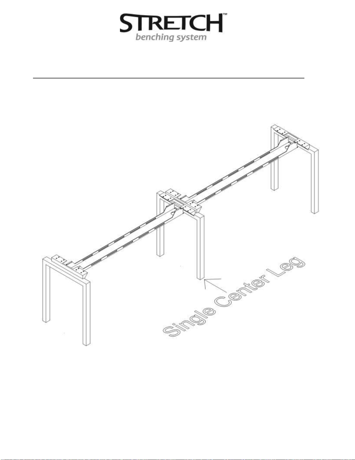
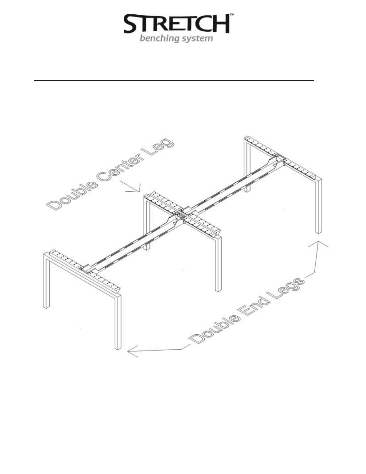
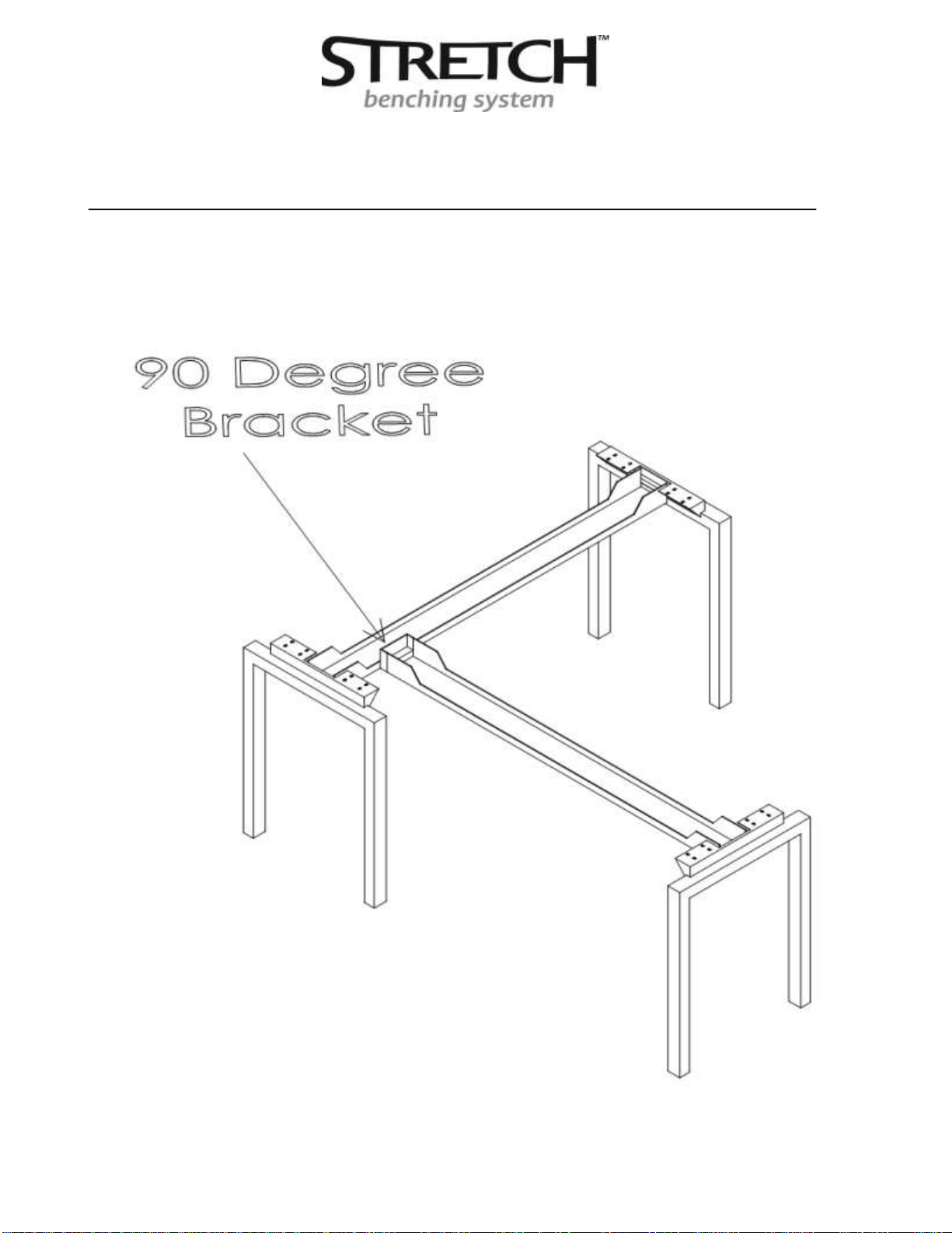
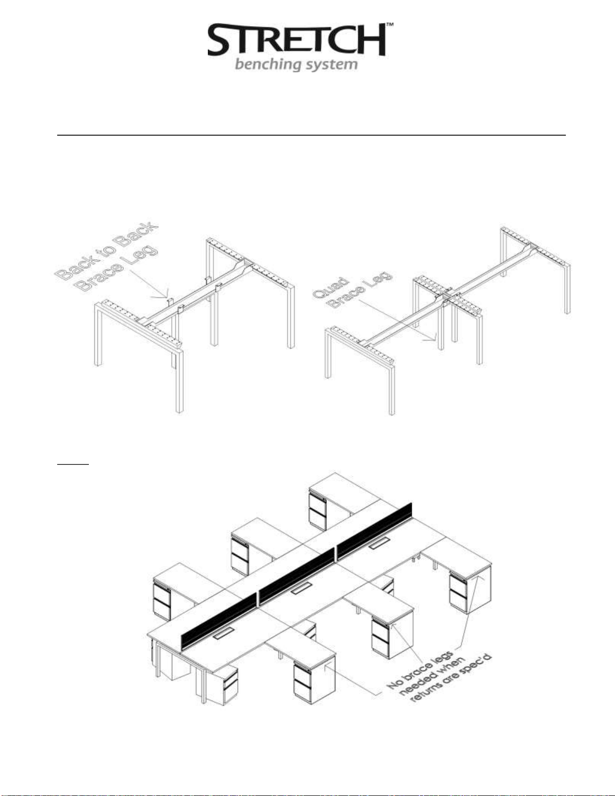
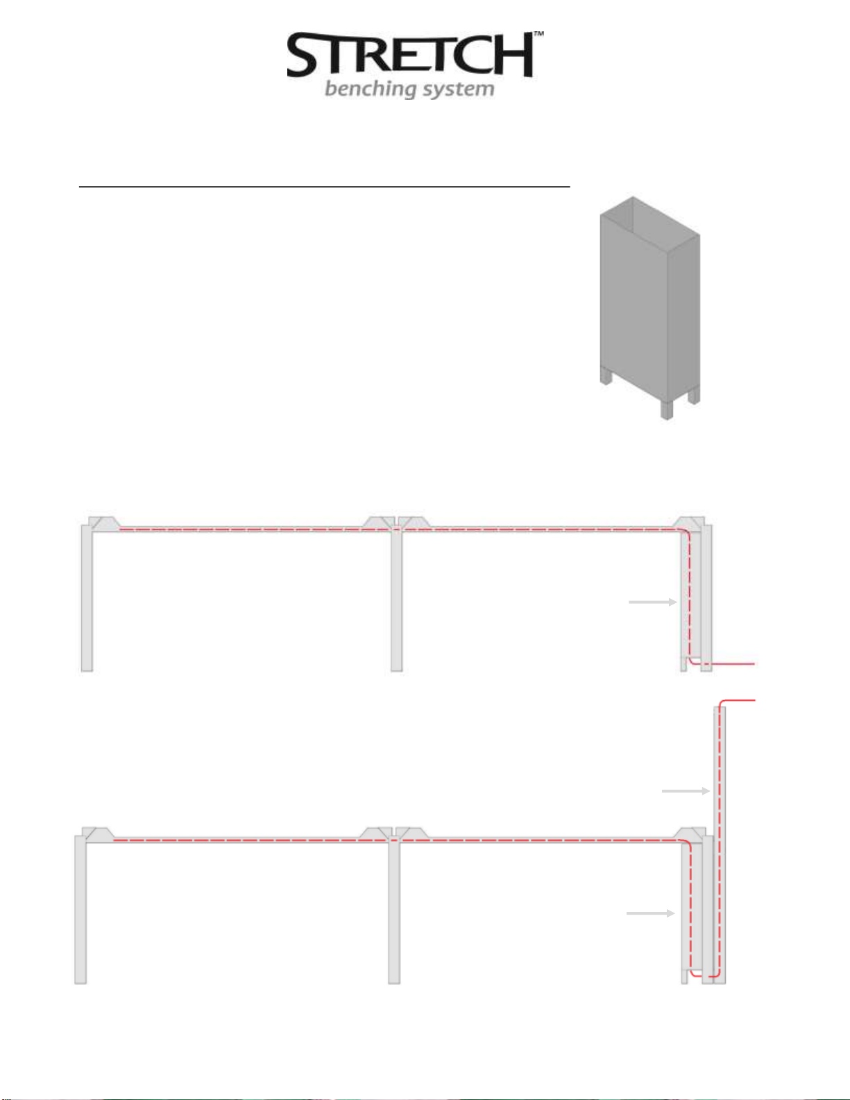
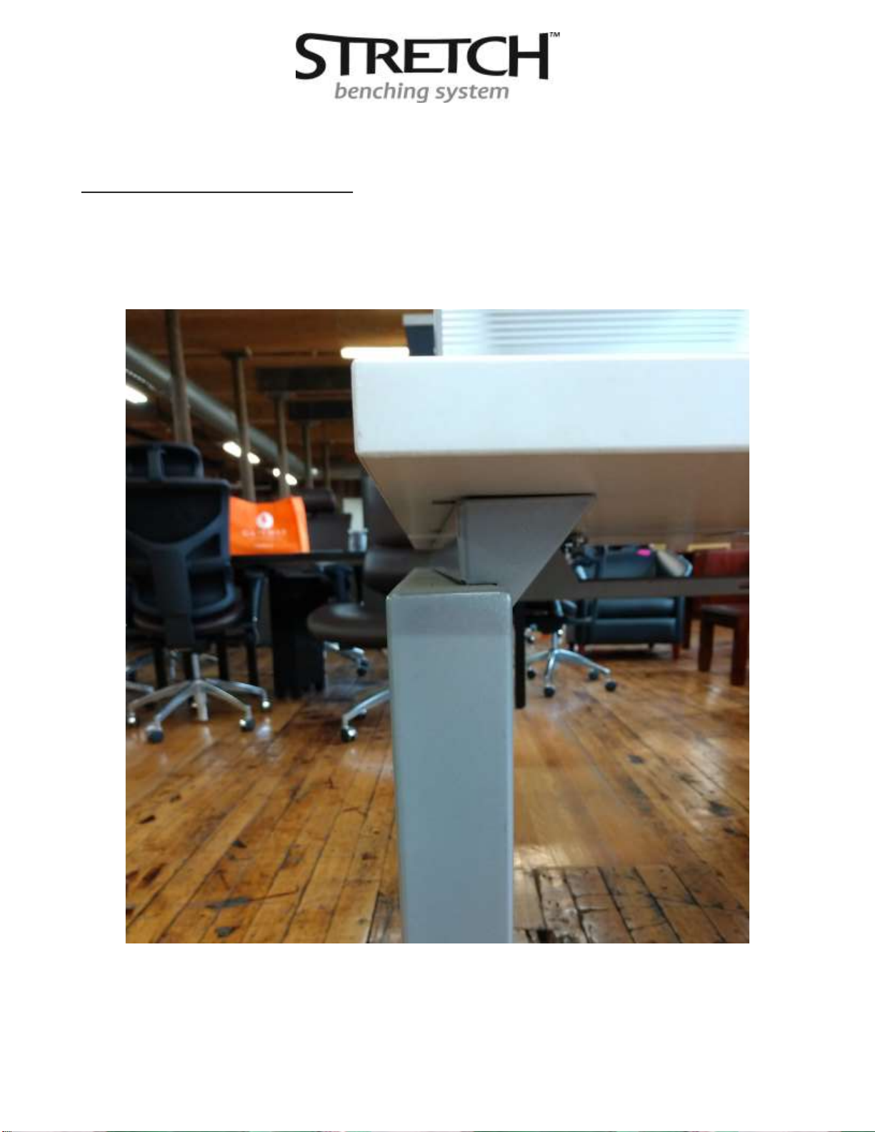
For Technical Assistance Please Call Conklin Oce Furniture
at 800.817.1187 or email support@conklinoce.com
Assembly Instructions
&
General Overview

2
For Technical Assistance Please Call Conklin Oce Furniture
at 800.817.1187 or email support@conklinoce.com
1. General Overview & Assembly Order………………………...Page 3
2. Assembling the Structural Components……………………Page 4-11
3. Power, Data, Power Poles and Cable Floor Boxes……….Page 12-17
4. Worksurfaces and Screen Brackets…………………………….Page 18-24
5. Final Check………………………………………………………………..Page 25

3
For Technical Assistance Please Call Conklin Oce Furniture
at 800.817.1187 or email support@conklinoce.com
General Overview
Stretch™ benching is a modular system designed to be easy to install and specify
as well as being easily re-congured. At the core of the system are the legs and cable
trays., which are able to extend or retract to accommodate multiple work surface
lengths without specifying additional components. The whole system can be
assembled with two allen wrenches and a drill with a phillips head driver.
NOTE: BECAUSE STRETCH IS AN ADJUSTABLE WIDTH SYSTEM IT IS IM-
PORTANT TO LEAVE ALL FASTENING SCREWS ON WORKSURFACES AND CA-
BLE TRAYS LOOSE UNTIL ALL WORKSURFACES HAVE BEEN PLACED AND
SCREEN BRACKETS HAVE BEEN INSTALLED . ONCE ALL COMPONENTS
ARE ALIGNED, SECURELY TIGHTEN ALL SCREWS.
Assembly Order
1. Assemble legs and cable trays
2. Place and position oor supporting storage
3. Lay in any cabling and power components
4. Place work surfaces and screen brackets
5. Fasten work surfaces to legs while leaving screen brackets in place but loose
6. Install screens into brackets and tighten brackets to screen and work surface
7. Level legs and oor supporting storage
8. Hang screen accessories
9. Tighten all screws!!!

4
For Technical Assistance Please Call Conklin Oce Furniture
at 800.817.1187 or email support@conklinoce.com
Structural Component Assembly (Cable Tray & Support Leg)
Remove the two screws and at plate from the receiver on the leg.
Insert teeth on cable tray into receiving slots on leg.
After inserting the teeth, the cable tray must be pushed down to lock the teeth into
the leg (a rubber hammer may be used to assist). Re-install the two hole plate and
tighten the screws to fully secure the cable tray.

5
For Technical Assistance Please Call Conklin Oce Furniture
at 800.817.1187 or email support@conklinoce.com
Structural Component Assembly (Cable Tray & Support Leg)
There are four types of main support legs (two types of single legs and two types of
double legs).
Single end legs are used at the end of runs or on both sides of a single free stand-
ing desk.

6
For Technical Assistance Please Call Conklin Oce Furniture
at 800.817.1187 or email support@conklinoce.com
Structural Component Assembly (Cable Tray & Support Legs)
Single center legs are used in between desks in the middle of runs and have cable
tray receivers on both sides.
The double legs are used in the same manner as the single legs but are used for pods
(back to back conguration)

7
For Technical Assistance Please Call Conklin Oce Furniture
at 800.817.1187 or email support@conklinoce.com
Structural Component Assembly (Cable Tray & Support Legs)
The double legs are used in the same manner as the single legs but are used for pods
(back to back conguration)

8
For Technical Assistance Please Call Conklin Oce Furniture
at 800.817.1187 or email support@conklinoce.com
Structural Component Assembly (Cable Tray & Support Legs)
Under worksuface cable management can be added to return worksurfaces by using a
90 degree bracket.

9
For Technical Assistance Please Call Conklin Oce Furniture
at 800.817.1187 or email support@conklinoce.com
Structural Component Assembly (Brace Legs)
In addition to the main support legs there are four brace legs used for stabilizing
when no return work surfaces are utilized. Brace legs are always installed
perpendicular to End legs and Center legs Two of the legs are used for single sided
run congurations and two of the legs are used for pod congurations. Refer to pages
9 and 10 for typical placement.

For Technical Assistance Please Call Conklin Oce Furniture
at 800.817.1187 or email support@conklinoce.com
Structural Component Assembly (Brace Leg Single & Double)
The rst two legs are used for single sided pods also know as runs ( Single Brace Leg
& Double Brace Leg). See below for typical installation locations.
Note: When return work surfaces are utilized brace legs are not necessary.

For Technical Assistance Please Call Conklin Oce Furniture
at 800.817.1187 or email support@conklinoce.com
Structural Component Assembly (Brace Leg Quad & Back to Back)
The other two legs are used for double sided pods (quad brace leg & brace leg back to
back). See below for typical installation locations.
Note: When return work surfaces are utilized brace legs are not necessary.

For Technical Assistance Please Call Conklin Oce Furniture
at 800.817.1187 or email support@conklinoce.com
Power Components & Installation
Below are the components that make up the power system. Power Bar with duplexes,
slide mount brackets and jumper or base infeed.

For Technical Assistance Please Call Conklin Oce Furniture
at 800.817.1187 or email support@conklinoce.com
Power Components & Installation
Slide the brackets into the end of the cable tray as shown

For Technical Assistance Please Call Conklin Oce Furniture
at 800.817.1187 or email support@conklinoce.com
Power Components & Installation
Slide the power bar on to the clips until secure.

For Technical Assistance Please Call Conklin Oce Furniture
at 800.817.1187 or email support@conklinoce.com
Power Components & Installation
Connect base power infeed to power bar and connect jumpers between power bars.
When power bars are in the desired location install the 4 securing screws that came
with the cable tray.

For Technical Assistance Please Call Conklin Oce Furniture
at 800.817.1187 or email support@conklinoce.com
Cable Floor Box & Power Pole (Cable Routing)
The cable oor box is a hollow box elevated by four
Legs to allow cabling to pass underneath and then
up to the cable tray.
The red line below shows the path of cable routing when coming from the wall
or oor.
Cable Floor Box
The red line below shows the path of cable routing when coming from
ceiling through the power / data pole. Power / Cable Pole
Cable Floor Box

For Technical Assistance Please Call Conklin Oce Furniture
at 800.817.1187 or email support@conklinoce.com
Network Cable Installation
Network cables shown installed in power way after power raceways and duplexes have
been installed.
Center legs are cut out in the middle to allow cables to pass through to the next tray

18
For Technical Assistance Please Call Conklin Oce Furniture
at 800.817.1187 or email support@conklinoce.com
Worksurface Installation
The main worksurfaces have threaded inserts pre-installed that match with the loca-
tion of the holes on the primary Stretch legs. 6MM machine screws are used to
attach the worksuface to the legs.

19
For Technical Assistance Please Call Conklin Oce Furniture
at 800.817.1187 or email support@conklinoce.com
Worksurface Installation
On end of runs worksurface edge should be ush with the Stretch leg.

20
For Technical Assistance Please Call Conklin Oce Furniture
at 800.817.1187 or email support@conklinoce.com
Worksurface Installation
Return worksurfaces are attached via wood screws and at brackets to the main work
surface.
Table of contents
Other Gateway Office Furniture Indoor Furnishing manuals
Popular Indoor Furnishing manuals by other brands

Emmezeta
Emmezeta HMBK203 Assembling Instruction

MARCKERIC
MARCKERIC 13862 Assembly instructions

AMERLIFE
AMERLIFE USATVN1016600 Assembly instructions

Living Spaces
Living Spaces Mateo 7030-01100 Assembly instructions

Furniture of America
Furniture of America CM3744SC-2PK Assembly instructions

American Standard
American Standard Doral Classic Champion 2076 installation instructions