Step 1 - Install the oor mount bin within the cupboard
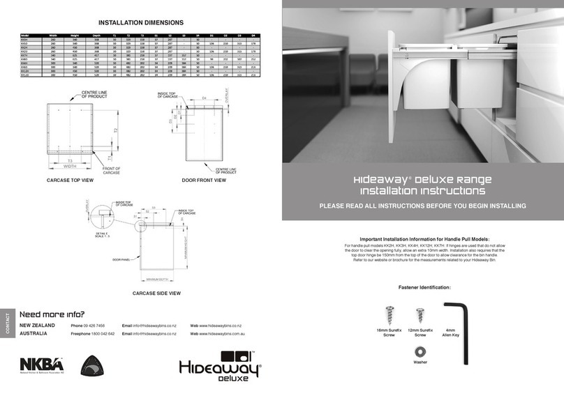
(refer to the Installation Dimensions on the back page)
• With the bin standing on the oor mount brackets, fully extend the runners and remove the buckets.
• Close the runners fully.
FLOOR MOUNT HANDLE PULL MODELS ONLY
• Place the unit inside the cabinet in the desired location (ideally place the bin in the centre of the space provided). Secure to base of cabinet
using screws provided. Mounting holes are located at the base of the oor mount brackets.
• If hinges are used on the door that do not allow the handle of the bin to clear the opening fully, allow an extra 10mm width.
• Move on to step 5.
FLOOR MOUNT DOOR PULL MODELS ONLY
• Place the unit inside the cabinet in the desired location (ideally place the bin in the centre of the space provided). Secure to base of cabinet
using screws provided. Mounting holes are located at the base of the oor mount brackets.
• Move on to step 2.
Step 2 – Predrilling the Door Panel (Door Pull Models Only)
• Mark the vertical centre line of the product down the rear of the door panel.
• Mark the overlay at the bottom of the door panel.
• With reference to the Installation Dimensions mark the D2 Door Mount positions.
• Drill a 2mm hole 10mm deep at each of the marked positions.
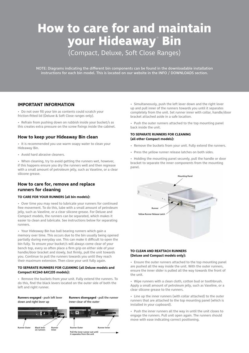
Step 3 – Remove the inner runner with collar and door bracket attached (refer FIG 3 & 4)
• Fully extend the runners.
• Find the black levers located on the outer side of both the left and right runner.
• Simultaneously, push the left lever up and the right lever down and pull inner of the runners towards you until it separates completely from the
unit. Set runner inner (with collar and door bracket attached) aside in a safe location.
• Push the outer runners attached to the top mounting panel back inside the unit.
Step 4 – Mounting and Adjusting the Door Panel (Door Pull Models Only) Refer FIG 2
• Position the door bracket on the door panel and align with the predrilled holes.
• Secure the door bracket using a 12mm Surex Screw in each of the 2 vertical slots.
• Reattach the runner inner – Refer to FIG 4.
1. Ensure the outer runners attached to the mounting panel are pushed as far as they will go into the unit.
2. Ensure the inner slider is forward as far as it will go.
3. Line up the inner runners (with the collar and door bracket attached) to the outer runners.
4. Push the inner runners into position until the unit is fully closed. There may be some resistance when pushing the unit closed but
the runner should operate smoothly after reassembly.
• Adjust the angle of the door panel by loosening the two M6 nuts and bolts, moving the door panel so it is parallel with the carcase and
retightening the M6 nuts and bolts.
• Adjust the vertical position of the Door Panel by loosening the 2 Surex Screws in the vertical slots and moving the panel as required.
• Drill a 2mm pilot hole 10mm deep at the centre of each of the horizontal slots.
• Secure the door panel using 12mm sure x screws through the 4 horizontal slots.
• If required adjust the horizontal position of the door panel by removing the 2 screws in the vertical slots, loosening the screws in the horizontal
slots, adjusting the panel position and retightening the screws in the horizontal slots.
• Reinstall the 2 screws into the vertical slots. Additional pilot holes may need to be drilled.
Step 5 – Place the bin bucket(s) into the collar.
• Check that the bin opens and closes smoothly and that there is no contact between the bin and the mounting panel.
• Please leave the Care and Maintenance instructions inside the bucket for the owner.
FIG 3 FIG 4FIG 2 - Door Pull Model
M6 Bolt
Door Bracket
Vertical Slot
Horizontal Slot
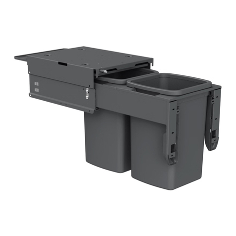
FIG 1 - Bin Parts
Friction Fitted Lid
Handle Pull
Liner Holder
Runner
Floor Mount Brackets Floor Mount Brackets
Runner Release Latch
Bucket
INSTALLATION INSTRUCTIONS START HERE
Runners engaged - push left lever down
and right lever up
Runner Outer Runner Inner
Black lever on runners
Runner Outer Runner Inner
Pull the inner runner out until it separates
from the unit
Runners disengaged - pull the runner inner
clear of the outer


