GATEWORKS GW2342 User manual

AVILA
NETWORK COMPUTER
Operating Manual
For
GW2342 Network Processor
Document #10000330
Revision 06
1 October 2005
Copyright 2005

Avila Network Computer Operating Manual
2of 25
TABLE OF CONTENTS
1. INTRODUCTION.....................................................................................................................................4
1.1. Product Description..........................................................................................................................4
1.2. Standard Features .............................................................................................................................4
1.3. Ordering Options –Standard Configuration*.................................................................................4
1.4. Functional Blocks..............................................................................................................................5
Processor......................................................................................................................................................6
IXP42x Processor Feature Comparison....................................................................................................6
SDRAM........................................................................................................................................................6
Flash..............................................................................................................................................................6
Compact Flash .............................................................................................................................................6
Mini-PCI Sockets.........................................................................................................................................7
Ethernet ........................................................................................................................................................7
EEPROM......................................................................................................................................................7
Real Time Clock..........................................................................................................................................7
Temperature and Voltage Monitor.............................................................................................................7
Fan Speed Controller...................................................................................................................................8
Serial I/O ......................................................................................................................................................8
Digital I/O ....................................................................................................................................................8
USB ..............................................................................................................................................................8
JTAG Port ....................................................................................................................................................8
Status LED and Push Button Reset ............................................................................................................8
DC/DC Converter........................................................................................................................................8
2. CONFIGURATION AND INSTALLATION.......................................................................................9
2.1. Memory Mapping...............................................................................................................................9
2.2. PCI Device Mapping.......................................................................................................................10
2.3. Interrupt Mapping...........................................................................................................................10
2.4. Digital I/O Mapping........................................................................................................................11
2.5. Interface Connectors.......................................................................................................................12
Mini-PCI Sockets (J1, J2, J3, J4)..............................................................................................................13
Compact Flash Socket (J5)........................................................................................................................15
COM2 Serial Port Header (J6)..................................................................................................................16
JTAG Port Header (J7)..............................................................................................................................16
Digital I/O Header (J8)..............................................................................................................................16
Power Connector (J9)................................................................................................................................17
Ethernet Connectors (J10, J11).................................................................................................................17
USB Device Connector (J12)....................................................................................................................18
COM1 Serial Port Connector (J13)..........................................................................................................18
Fan Controller (J14)...................................................................................................................................18
Auxiliary Power (J17)...............................................................................................................................19
2.6. JTAG Programming........................................................................................................................19
2.7. Getting Started.................................................................................................................................20
2.8. Manufactures Website Links / Support Mailing List.....................................................................20
Hardware ....................................................................................................................................................20
Software......................................................................................................................................................21

Avila Network Computer Operating Manual
3of 25
3. SPECIFICATIONS.................................................................................................................................22
3.1. Electrical..........................................................................................................................................22
3.2. Mechanical.......................................................................................................................................22
3.3. Environmental..................................................................................................................................22
4. CUSTOMER SUPPORT........................................................................................................................23
4.1. Product Revision History................................................................................................................23
4.2. Technical Assistance........................................................................................................................24
4.3. Warranty...........................................................................................................................................24
4.4. Return for Repair.............................................................................................................................24
4.5. Life Support Policy..........................................................................................................................25
4.6. Trademarks......................................................................................................................................25

Avila Network Computer Operating Manual
4of 25
1.INTRODUCTION
1.1. Product Description
The GW2342 is a member of the Gateworks Avila Network Processor family. The
GW2342 meets the requirements for enterprise and residential network
applications. This single board network processor consists of an IntelIXP series
XScaleCPU operating at speeds up to 533MHz, up to 128Mbytes of SDRAM,
and up to 32Mbytes of Flash. Peripherals include four Type III Mini-PCI slots, two
10/100 Base-TX Ethernet channels, Type B USB device controller, Compact
Flash socket, and two RS232 serial ports for management and debug. Additional
features include serial EEPROM, real time clock, voltage and temperature
monitor, fan controller, watchdog timer, passive power over Ethernet, digital I/O,
and a wide range DC/DC power supply. Software support includes Linux and
VxWorksoperating systems.
1.2. Standard Features
♦IntelXScaleIXP42x Processor Operating at Speeds up to 533MHz
♦Up to 128Mbytes SDRAM
♦Up to 32Mbytes Flash
♦Up to four Type III Mini-PCI Slots
♦Two 10/100 Base-TX Ethernet Ports
(Auto MDI/MDIX)
♦Type B USB Device
♦Compact Flash Socket
♦Two RS-232 Serial Ports
♦2Kbyte Serial EEPROM
♦Battery Powered Real
Time Clock
♦Voltage and Temperature Monitor
♦Watchdog Timer
♦General Purpose I/O
♦User LED and Push Button Reset
♦Passive Power Over Ethernet
♦6-28VDC Input Voltage Range
♦Reverse Voltage and Transient Protection
♦14W available for Mini-PCI Sockets
♦3W Typical Operating Power
♦0°C to 70°C Operating Temperature
♦Software Support for Linux and VxWorks
♦1 Year Warranty
1.3. Ordering Options –Standard Configuration*
Order Code Processor SDRAM Flash Mini-PCI
GW2342-C2R2F1E4
IXP425 (533MHz) 64Mbytes 16Mbytes 4
* Contact factory for different configurations of CPU, DRAM, Flash, number of Mini-PCI sockets and
selection of peripherals
Avila Network Computer Operating Manual
5of 25
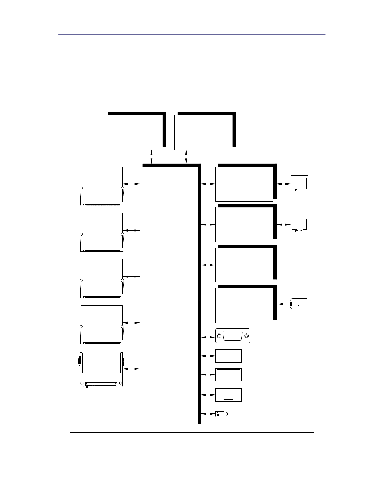
1.4. Functional Blocks
The functional block diagram for the GW2342 network processor is shown below
followed by a detailed description of each major functional block. The network
processor includes several options that are specified at the time of ordering.
Options include the processor type, amount of system memory, amount of Flash
memory, and number of Mini-PCI sockets.
ETHERNET
10/100 PHY
ETHERNET
10/100 PHY
SDRAM
32-128Mbytes
MINI-PCI
SOCKET
MINI-PCI
SOCKET
JTAG
POWER
STATUS LED
XSCALE
PROCESSOR
IXP420@266MHz
to
IXP425@533MHZ
FLASH
16-32Mbytes
MINI-PCI
SOCKET
MINI-PCI
SOCKET
RS232
DIO
COMPACT
FLASH
SOCKET
RS-232
SERIAL EEPROM
REAL TIME CLOCK
SYSTEM MONITOR
FAN CONTROLLER
DC/DC
CONVERTER
6-28V@18W
GW2342 Functional Block Diagram

Avila Network Computer Operating Manual
6of 25
Processor
The GW2342 supports the IntelIXP420, IXP422 and IXP425 processors. The
features common to these processors are listed below. The primary difference
between these processors is support for encryption, operating speed, operating
temperature and cost. See the following table below for the differences between
the processor families.
•StrongARM Version 5TE Compliant
•Network processing engines to offload Ethernet filtering
•32-bit SDRAM interface operating at 133MHz
•32-bit PCI interface operating at 33MHz for Mini-PCI support
•16-bit Expansion interface for Flash support
•Two 802.3 MII/RMII interfaces for Ethernet PHY support
•USB 1.1 device controller
•Two serial ports
•Four internal timers
•Internal bus performance monitoring unit
•General purpose Input/Outputs
•Watchdog Timer
Feature IXP420 IXP422 IXP425
Speed (MHz) 266, 400, 533 266 266, 400, 533
Hardware Encryption No Yes Yes
Extended Temperature 266 only No 266, 400, 533
Cost Low Mid High
IXP42x Processor Feature Comparison
SDRAM
The DRAM resides in two synchronous DRAM devices soldered directly to the
board. This architecture supports SDRAM memory capacities from 32Mbytes up
to 128Mbytes. The 32-bit SDRAM interface operates at 133MHz. The Gateworks
standard shipping configuration is 64Mbytes.
Flash
The Flash resides in one or two J3 Intel StrataFlashdevices soldered directly to
the board. This architecture supports Flash memory capacities from 4Mbytes up
to 32Mbytes. The 16-bit Flash interface operates at 33MHz. The Gateworks
standard shipping configuration is 16Mbytes.
Compact Flash
The GW2342 supports a single Compact Flash socket located on the rear of the
board. The Compact Flash socket accepts small removable mass storage cards
with storage capacities up to 4Gbytes.

Avila Network Computer Operating Manual
7of 25
Mini-PCI Sockets
Mini-PCI is a small form factor PCI card that uses the same signal protocol,
electrical specifications, and configuration definitions as conventional PCI. There
are up to four Mini-PCI sockets available on the GW2342. There are a wide
variety of Mini-PCI cards available for expanding the networking functionality of
the GW2342. Even though the mini-PCI specification limits the socket operating
power to 2.5W, there is a total of 14W to be distributed as needed.
Ethernet
The GW2342 supports two Ethernet ports using an Intel LXT973 PHY
Transceiver. Both channels operates in a 100BASE-TX or 10BASE-T
configuration and support auto MDI/MDIX for automatically switching twisted pair
inputs and outputs. Additional features include full-duplex operation for both
10Mbps and 100Mbps configurations as well as support for auto-negotiation. The
Ethernet ports are available through standard RJ45 connectors. The connectors
have two integrated status lights. The green status light indicates link and
activity. The light is on for link and blinking for activity. The yellow status light
indicates speed. The light is on for 100Mbps and off for 10Mbps.
EEPROM
The Atmel AT24C16AN is an Electrically Erasable Programmable Read Only
Memory (EEPROM) with 16Kbits of storage. The 16kbits of storage is organized
in a 2048 x 8-bit configuration. Additional features include 1,000,000 erase/write
cycles and a 100-year minimum data retention time. Data is transmitted to and
from the EEPROM over the processor I2C bus. The I2C clock frequency is 0 to
400KHz. The I2C base address is A0 hex for writes and A1 hex for reads.
Real Time Clock
The Dallas Semiconductor DS1672 is designed to count seconds and can be
used to derive time-of-day, week, month, and year using software. A battery
ensures uninterrupted operation when the main power supply drops below the
battery voltage. The battery capacity is 35mAH. The real time clock requires
0.425 micro amps typical and 1 micro amp maximum for backup operation. This
results in a battery life of 4 years minimum and more than 9 years typical. Data is
transmitted to and from the Real Time Clock over the processor I2C bus. The I2C
clock frequency is 0 to 400KHz. The I2C base address is D0 hex for writes and
D1 hex for reads.
Temperature and Voltage Monitor
The Analog Devices AD7418 provides temperature and voltage monitoring
capability. The GW2342 operating temperature is monitored through this device.
The temperature accuracy is ±1°C at 25°C and ±2°C over the entire temperature
range of -40°C to +125°C. The GW2342 input voltage is also monitored through
this device. A resistor divider is used on the A/D input to scale the input voltage
down. Multiple the A/D voltage reading by 23.1 to get the actual input voltage.
Data is transmitted to and from the Temperature and Voltage Monitor over the

Avila Network Computer Operating Manual
8of 25
processor I2C bus. The I2C clock frequency is 0 to 400KHz. The I2C 7-bit base
address is 50 hex for writes and 51 hex for reads.
Fan Speed Controller
Fan speed control increases fan service life and decreases system acoustic
airflow noise. The GW2342 includes a Microchip TC653BE that controls the
speed of a fan based on temperature. This device keeps the fan off until the
GW2342 temperature reaches 35 degrees Celsius. The controller adjusts the fan
speed from 50% to 100% between 35 and 45 degrees Celsius.
Serial I/O
The GW2342 includes two RS232 serial I/O ports. One serial I/O port is available
through a 10-pin header and the other is available through a 9-pin female D-shell
connector. The serial ports are 16550-compliant UARTs with additional depth for
both the transmit and receive buffers. The interface supports transfer rates from
1200bps up to 120Kbps.
Digital I/O
The IXP processor includes a 16 bits of digital I/O. Some of these signals are
used for controlling and monitoring the status of devices local to the GW2342
and some of them are available on a 10-pin header for application use. The
function of each digital I/O signal is described in Section 2, Digital I/O Mapping.
USB
The GW2342 includes a version 1.1 Device Controller interface. The interface
operates as a half-duplex, slave-only device at a baud rate of 12Mbps. The
interface does not operate as a USB host. A standard USB Type B connector is
provided on the board.
JTAG Port
A JTAG debug port is available to facilitate program download directly into Flash
memory. See Section 2, JTAG Programming, for more information.
Status LED and Push Button Reset
The GW2342 includes a status LED and a push button reset. The LED is
connected to the digital I/O and can be controlled by software. See Section 2
Configuration and Installation for the mapping of the LED.
DC/DC Converter
A switching DC/DC converter supplies power to the GW2342. This allows the
board to support a wide input voltage range and low power operation. The
DC/DC has a minimum input voltage of 6VDC and a maximum of 28VDC. DO
NOT EXCEED THE 28VDC INPUT MAXIMUM OR DAMAGE MAY OCCUR TO
THE BOARD. Also note that if a power over Ethernet injector is used to power
the board, there will be voltage loss due to the resistance of the Ethernet cable.
This should be taken into account when sizing the voltage supply.

Avila Network Computer Operating Manual
9of 25
2.CONFIGURATION AND INSTALLATION
The following section gives memory, interrupt, I2C and digital I/O mappings
specific to the GW2342. See the Intel IXP4XX Product Line and IXC1100 Control
Plane Processors Developer’s Manual for more information on these interfaces.
2.1. Memory Mapping
The memory map and Expansion bus chip select mapping for the GW2342 is
shown below.
Memory Address Size Description
0000_0000 –0FFF_FFFF 256Mbyte Flash Memory (32Mbyte max)
0100_0000 –2FFF_FFFF 756Mbyte SDRAM Memory (128 Mbyte max)
3000_0000 –3FFF_FFFF Reserved
4000_0000 –47FF_FFFF Reserved
4800_0000 –4FFF_FFFF 128Mbyte PCI Bus
5000_0000 –5FFF_FFFF 256Mbyte Expansion Bus
6000_0000 –63FF_FFFF 64Mbyte Queue Manager
6400_0000 –BFFF_FFFFReserved
C000_0000 –C3FF_FFFF 64Mbyte PCI Controller Configuration and Status
C400_0000 –C7FF_FFFF 64Mbyte Expansion Bus Configuration
C800_0000 –C800_0FFF 1Kbyte COM1 Serial Port
C800_1000 –C800_1FFF 1Kbyte COM2 Serial Port
C800_2000 –C8FF_2FFF 1Kbyte Performance Monitor
C800_3000 –C8FF_3FFF 1Kbyte Interrupt Controller
C800_4000 –C8FF_4FFF 1Kbyte GPIO Controller
C800_5000 –C8FF_5FFF 1Kbyte Timers
C800_6000 –C8FF_6FFF 1Kbyte Reserved
C800_7000 –C8FF_7FFF 1Kbyte Reserved
C800_8000 –C8FF_8FFF 1Kbyte Reserved
C800_9000 –C8FF_9FFF 1Kbyte Ethernet MAC A
C800_A000 –C8FF_AFFF 1Kbyte Ethernet MAC B
C800_B000 –C8FF_BFFF 1Kbyte USB Controller
C800_C000 –C800_FFFF Reserved
C801_0000 –CBFF_FFFF Reserved
CC00_C000 –CC00_00FF 256byte SDRAM Configuration Registers
CC00_0100 –FFFF_FFFF Reserved
Note: The bottom 256Mbytes is configurable through bit 31 of the EXP_CONFG0 register.
Memory Map
Chip
Select Description
CS0 Flash Memory (U3)
CS1 Compact Flash Socket #CS0 (J5)
CS2 Compact Flash Socket #CS1 (J5)
CS3 Flash Memory (U4)
CS4-CS7 Not Used
Expansion Bus Chip Selects

Avila Network Computer Operating Manual
10 of 25
2.2. PCI Device Mapping
The GW2342 PCI device mapping is listed below.
Bus
Number
Device
Number
Fcn
Number
IRQ
Number
Description
00 01 028 Mini-PCI Slot (J3)
00 02 027 Mini-PCI Slot (J1)
00 03 026 Mini-PCI Slot (J4)
00 04 025 Mini-PCI Slot (J2)
PCI Device Map
2.3. Interrupt Mapping
The IXP42X processor allows for 32 interrupts which originate from either internal
processor blocks or from the 14 dedicated GPIO pins. The interrupt mapping is
shown below.
Interrupt Function
0WAN/HSS NPE –Not Used
1Ethernet NPE A
2Ethernet NPE B
3Queue Manager (1-32)
4Queue Manager (33-64)
5General Purpose Timer 0
6GPIO(0)
7GPIO(1)
8PCI Interrupt -Not Used
9PCI DMA Channel 1
10 PCI DMA Channel 2
11 General Purpose Timer 1
12 USB
13 Console UART
14 Timestamp Timer
15 High-Speed UART –Not Used
16 Watchdog Timer
17 Performance Monitoring Unit
18 XScale PMU
19 GPIO(2)
20 GPIO(3)
21 GPIO(4)
22 GPIO(5) -Not Used (Serial Enable)
23 GPIO(6) -Not Used (I2C Bus SCL)
24 GPIO(7) -Not Used (I2C Bus SDA)
25 GPIO(8) -Mini-PCI Slot
J2 -INTA
J4 –INTB
26 GPIO(9) -Mini-PCI Slot
J4 -INTA

Avila Network Computer Operating Manual
11 of 25
J1 –INTB
27 GPIO(10) -Mini-PCI Slot
J1 -INTA
J3 -INTB
28 GPIO(11) -Mini-PCI Slot
J3 -INTA
J2 -INTB
29 GPIO(12) –Compact Flash
30 SW Interrupt 0
31 SW Interrupt 1
Interrupt Map
2.4. Digital I/O Mapping
The GW2342 uses the IXP42x Processor digital I/O for controlling and monitoring
the status of various devices. The IXP42x processor includes three 16-bit
registers for configuring, initializing, and using the digital I/O. The output enable
register (GPOER) configures each bit as an input or output. The data output
register (GPOUTR) controls the digital I/O configured as outputs. The input
register (GPINR) reads the digital I/O configured as inputs. See the Intel IXP4XX
Product Line and IXC1100 Control Plane Processors Developer’s Manual –
Chapter 13. The digital I/O bit mapping is shown below.
GPIO Bit Description
0
1
2
3
4
5
6
7
8
9
10
11
12
13
14
15
Digital I/O Header (J8 pin 1) input or output
Digital I/O Header (J8 pin 3) input or output
Digital I/O Header (J8 pin 5) input or output
Digital I/O Header (J8 pin 7) input or output
Shared with Status LED output 0=on and 1=off
Digital I/O Header (J8 pin 9) input or output.
Reserved
I2C Bus -SCL
I2C Bus -SDA
Mini-PCI Interrupt -See IRQ Map (Section 2.3)
Mini-PCI Interrupt -See IRQ Map (Section 2.3)
Mini-PCI Interrupt -See IRQ Map (Section 2.3)
Mini-PCI Interrupt -See IRQ Map (Section 2.3)
Compact Flash Interrupt –See IRQ Map (Section 2.3)
PCI Reset input 0 = active and 1=inactive
Reserved for Watchdog Timer Strobe
Reserved
Digital I/O Map
Avila Network Computer Operating Manual
12 of 25
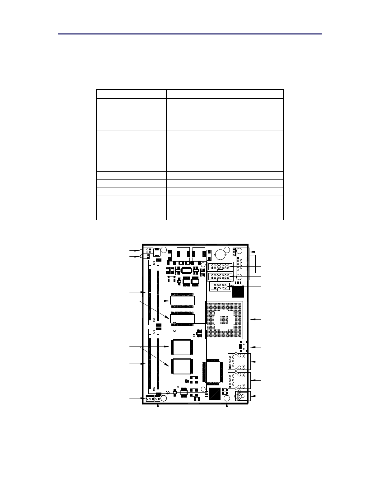
2.5. Interface Connectors
The Gw2342 interface connector pin assignments and signal descriptions are
included in the following sections. The connectors are listed in the table below
and the connector locations are shown in the following diagrams.
Connector Function
J1 Mini-PCI Socket Top Side
J2 Mini-PCI Socket Bottom Side
J3 Mini-PCI Socket Top Side
J4 Mini-PCI Socket Bottom Side
J5 Compact Flash Socket Bottom Side
J6 COM2 Serial Port Header
J7 JTAG Port Header
J8 Digital I/O Header
J9 Power Connector
J10 Ethernet Connector
J11 Ethernet Connector
J12 USB Device Connector
J13 COM1 Serial Port Connector
J14 Fan Controller
J17 Auxiliary Power
Connectors
Power (J9)
Ethernet 1 (J10)
Ethernet 2 (J11)
USB Device (J12)
IXP Processor
Serial Port 2 (J6)
JTAG Port (J7)
GPIO Port (J8)
Serial Port 1 (J13)
Push Button Reset
User Status LED
Mini-PCI Socket (J3)
Mini-PCI Socket (J1)
Fan Control (J14) Mounting Holes
(4 places)
System Flash
System SDRAM
Auxiliary Power (J17)
Top Side Component Locations

Avila Network Computer Operating Manual
13 of 25
Compact Flash (J5)
Mini-PCI (J2)
Mini-PCI (J4)
Bottom Side Component Locations
Mini-PCI Sockets (J1, J2, J3, J4)
There are four Mini-PCI sockets for expanding the peripheral support with high-
speed PCI devices. The GW2342 supports standard 3.3V Mini-PCI cards.
Support is not provided for audio, modem, and networking sideband signaling as
defined in the Mini-PCI specification. The GW2342 Mini-PCI connector signaling
is illustrated in the following table.

Avila Network Computer Operating Manual
14 of 25
Pin
Signal Connect Pin
Signal Connect Pin
Signal Connect
1TIP NC 44 AD26 AD26 87 AD7 AD7
2RING NC 45 CBE3# CBE3# 88 VCC3 VCC3
3LANRXP NC 46 AD24 AD24 89 VCC3 VCC3
4LANTXP NC 47 AD23 AD23 90 AD6 AD6
5LANRXN NC 48 IDSEL IDSEL 91 AD5AD5
6LANTXN NC 49 Ground Ground 92 AD4 AD4
7LANRSV NC 50 Ground Ground 93 Reserved Reserved
8LANRSV NC 51 AD21 AD21 94 AD2 AD2
9LANRSV NC 52 AD22 AD22 95 AD3 AD3
10 LANRSV NC 53 AD19 AD19 96 AD0 AD0
11 LANGNP NC 54 AD20 AD20 97 VCC5 NC
12 LANRNN NC 55 Ground Ground 98 Reserved Reserved
13 LANYEP NC 56 PAR PAR 99 AD1 AD1
14 LANYEN NC 57 AD17 AD17 100 Reserved Reserved
15 CHSGND CHSGND 58 AD18 AD18 101 Ground Ground
16 Reserved Reserved 59 CBE2# CBE2# 102 Ground Ground
17 INTB# INTB# 60 AD16 AD16 103 ACSYNC NC
18 VCC5 NC 61 IRDY# IRDY# 104 M66EN NC
19 VCC3 VCC3 62 Ground Ground 105 ACDIN NC
20 INTA# INT# 63 VCC3 VCC3 106 ACDOUT NC
21 Reserved Reserved 64 FRAME# FRAME# 107 ACCLK NC
22 Reserved Reserved 65 CLKRUN#
Pull Down 108 ACID0 NC
23 Ground Ground 66 TRDY# TRDY# 109 ACID1 NC
24 VCC3AX VCC3 67 SERR# SERR# 110 ACRST NC
25 CLK CLK 68 STOP# STOP# 111 AMON NC
26 RST# RST# 69 Ground Ground 112 Reserved Reserved
27 Ground Ground 70 VCC3 VCC3 113 AGND NC
28 VCC3 VCC3 71 PERR# PERR# 114 Ground Ground
29 REQ# REQ# 72 DEVSEL# DEVSEL# 115 AOUT NC
30 GNT# GNT# 73 CBE1# CBE1# 116 AIN NC
31 VCC3 VCC3 74 Ground Ground 117 AGND NC
32 Ground Ground 75 AD14 AD14 118 AINGND NC
33 AD31 AD31 76 AD15 AD15 119 AGND NC
34 PME# NC 77 Ground Ground 120 AGND NC
35 AD29 AD29 78 AD13 AD13 121 Reserved Reserved
36 RSVD RSVD 79 AD12 AD12 122 MPCIACT NC
37 Ground Ground 80 AD11 AD11 123 VCC5AX NC
38 AD30 AD30 81 AD10 AD10 124 VCC3AX VCC3
39 AD27 AD27 82 Ground Ground 125 CHSGND CHSGND
40 VCC3 VCC3 83 Ground Ground 126 CHSGND CHSGND
41 AD25 AD25 84 AD9 AD9 127 NC NC
42 AD28 AD28 85 AD8 AD8 128 NC NC
43 Reserved Reserved 86 CBE0# CBE0#
Mini-PCI Connector

Avila Network Computer Operating Manual
15 of 25
Compact Flash Socket (J5)
The pin assignment for the industry standard Compact Flash socket is shown
below. The Compact Flash is connected to the expansion bus on the IXP
processor. The GW2342 Compact Flash connector signaling is illustrated in the
following table. The Compact Flash interrupt mapping is listed in Section 2,
Interrupt Mapping.
Pin Signal Connect Pin Signal Connect
1Ground Ground 26 CD1# No Connect
2D3 EXP D3 27 D11 EXP D11
3D4 EXP D4 28 D12 EXP D12
4D5 EXP D5 29 D13 EXP D13
5D6 EXP D6 30 D14 EXP D14
6D7 EXP D7 31 D15 EXP D15
7CS0# EXP CS1# 32 CS1# EXP CS2#
8A10 EXP A10 33 VS1# No Connect
9ATASEL# Ground 34 IORD# EXP RD#
10 A09 Ground 35 IOWR# EXP WR#
11 A08 Ground 36 WE# Pull Up
12 A07 Ground 37 INTRQ No Connect
13 VCC VCC 38 VCC VCC
14 A06 Ground 39 CSEL# Ground
15 A05 Ground 40 VS2# No Connect
16 A04 Ground 41 RESET# RESET#
17 A03 Ground 42 IORDY# No Connect
18 A02 EXP A2 43 INPACK# No Connect
19 A01 EXP A1 44 REG# Pull Up
20 A00 EXP A0 45 DASP# No Connect
21 D00 EXP D0 46 PDIAG# No Connect
22 D01 EXP D1 47 D08 EXP D8
23 D02 EXP D2 48 D09 EXP D9
24 IOCS16# No Connect 49 D10 EXP D10
25 CD2# No Connect 50 GND GND
Compact Flash Connector

Avila Network Computer Operating Manual
16 of 25
COM2 Serial Port Header (J6)
The COM2 serial port is available through a 10-pin header in a 2x5 configuration
with 0.1-inch pin spacing. The mating connector is an AMP/Tyco 746288-1,
available from Digi-Key as part number AKN10A-ND. The pin assignment
supports a ribbon cable connection to a standard 9-pin D-shell connector.
Pin Signal Pin Signal
1No Connect 2No Connect
3Transmit Data 4Clear To Send
5Receive Data6Request To Send
7No Connect 8No Connect
9Ground 10 No Connect
COM2 Serial Port Header
JTAG Port Header (J7)
These JTAG port is available through a 14-pin header in a 2x7 configuration with
0.1-inch pin spacing. The mating connector is an AMP/Tyco 746288-2, available
from Digi-Key as part number AKN14A-ND. The primary purpose for the JTAG
Port is to facilitate program download into Flash memory.
Pin Signal Pin Signal
1VCC3 Pull Up 2Ground
3JTAG RST 4Ground
5JTAG TDI 6Ground
7JTAG TMS 8Ground
9JTAG TCK 10 Ground
11 JTAG TDO 12 Board Reset
13 VCC3 Pull Up 14 Ground
JTAG Port Header
Digital I/O Header (J8)
The digital I/O is available through a 10-pin header in a 2x5 configuration with
0.1-inch pin spacing. The mating connector is an AMP/Tyco 746288-1, available
from Digi-Key as part number AKN10A-ND. Note that GPIO3 is shared with the
status LED as described in Section 2, Digital I/O Mapping.
Pin Signal Pin Signal
1GPIO0 2Ground
3GPIO1 4Ground
5GPIO2 6Ground
7GPIO3 8Ground
9GPIO4 10 Ground
Digital I/O Header

Avila Network Computer Operating Manual
17 of 25
Power Connector (J9)
Power is applied to the GW2342 through a standard 2.5mm x 5.5mm barrel jack
or through either Ethernet Connector. The input voltage range is 6VDC minimum
and 28VDC maximum. The power jack should have the positive input voltage on
the inner sleeve and ground on the outer sleeve. The mating connector is a G/S
SR2048A, available from Jameco as part number 190537CJ. The schematic
symbol representing this configuration is shown below.
Power Connector
Ethernet Connectors (J10, J11)
The GW2342 contains two 10/100 Base-TX Ethernet channels. Both Ethernet
channels are available through standard 8-pin RJ45 connectors. Both Ethernet
connectors support passive power over Ethernet. This enables the GW2342
operating voltage to be provided through the Ethernet connector rather than the
Power connector. The input voltage range is 6VDC minimum and 28VDC
maximum.
Pin Signal Standard Wire
Color
1TX+ WHITE/ORANGE
2TX-ORANGE
3RX+ WHITE/GREEN
4PoE + V BLUE
5PoE +V WHITE/BLUE
6RX-GREEN
7GND WHITE/BROWN
8GND BROWN
Ethernet Connector J10
Pin Signal Standard Wire
Color
1TX+ WHITE/ORANGE
2TX-ORANGE
3RX+ WHITE/GREEN
4PoE + V BLUE
5PoE +V WHITE/BLUE
6RX-GREEN
7GND WHITE/BROWN
8GND BROWN
Ethernet Connector J11

Avila Network Computer Operating Manual
18 of 25
USB Device Connector (J12)
The GW2347 includes a Type B connector to support the USB Device
configuration. The interface does not operate as a USB host.
Pin Signal
1No Connect
2Data-
3Data+
4Ground
USB Device Connector
COM1 Serial Port Connector (J13)
The COM1 serial port connector is an industry standard female 9-pin D-shell
connector with the pin assignment given in the table below. The DCE pin
assignments permit a direct connection to a standard PC DTE port running
terminal emulation software. The mating connector for insulation displacement
ribbon cable is CW Industries CWR-280-09-000, available from Digi-Key as part
number CMM09G-ND.
Pin Number Signal
1No Connect
2Transmit Data
3Receive Data
4No Connect
5Ground
6No Connect
7Clear To Send
8Request To Send
9No Connect
COM1 Serial Port Connector
Fan Controller (J14)
The fan is connected to a 2-pin MTA connector. The mating connector is an
AMP/Tyco 770602-02, available from Digi-Key as part number A19490-ND. This
connector requires separate contacts AMP/Tyco 770666-2, available from Digi-
Key as part number A23962-ND.
Pin Number Signal
1Fan Power
2Fan Ground
Fan Speed Control Connector

Avila Network Computer Operating Manual
19 of 25
Auxiliary Power (J17)
Auxiliary power is available through a 3-pin MTA connector. The mating
connector is an AMP/Tyco 770602-03, available from Digi-Key as part number
A19491-ND. This connector requires separate contacts AMP/Tyco 770666-2,
available from Digi-Key as part number A23962-ND.
Pin Number Signal
1Input Power
2Reset#
3Ground
Auxiliary Power Connector
2.6. JTAG Programming
The GW2342 Flash memory is programmed through the JTAG port. Gateworks
offers a low cost GW16102 JTAG programmer that enables the developer to
program or recover the Flash image through a standard PC parallel port.
Gateworks also offers a GW16013 JTAG gang programmer for simultaneously
programming up to 16 GW2342 processors in a production environment.
The following are the steps required to use the GW16012 JTAG programmer.
1. Connect the GW16012 JTAG programmer to a PC parallel port using the
standard DB25 cable included with programmer.
2. Connect the 10-pin IDC female from the GW16012 dongle to the GW2342
JTAG connector.
3. Create a bootable DOS floppy with the FLASH.EXE program and the
binary image. The FLASH.EXE program is a DOS program, which must
be run from a DOS prompt, it cannot be run from a Windows DOS box.
The development kit CDROM contains both the FLASH.EXE program and
the default factory programmed image.
4. Insert the DOS bootable floppy, with the FLASH.EXE program and binary
image into the PC’s floppy drive and boot to DOS.
5. Run the FLASH.EXE program with the following syntax
CC:> flash image.bin {p} {v} where p=program, v=verify and image.bin is
the binary image.
Examples:
C:> flash gw2342.bin p
Program the Flash with the gw2342.bin image
C:> flash gw2342.bin v
Verify that the Flash matches the gw2342.bin image
C:> flash gw2342.bin pv
Program and verify the Flash with the gw2342.bin image

Avila Network Computer Operating Manual
20 of 25
2.7. Getting Started
The GW2342 is factory configured with Redboot v2.01 and a uCLinux port
programmed into Flash memory. The software is configured to use either serial
port for a serial console. To get started, connect a serial cable from to another
computer running a terminal software application such as Windows
HyperTerminal. Configure the terminal program for 115,200 baud, 8 data bits, 1
stop bit, no parity and no flow control. Apply power and watch for Redboot and
Linux output on the serial console.
It is also possible to communicate to the GW2342 using a telnet session over
Ethernet. First, connect the J10 Ethernet port on the GW2342 to the Ethernet
port on a Host Computer using either a standard or a crossover cable. The
default telnet address for the GW2342 is 192.168.3.2. Second, configure the
Host Computer IP address to be on the same subnet (i.e. 192.168.3.99). Third,
switch to Host Computer to a command prompt and type C:>telnet 192.168.3.2.
The GW2342 console information will now be routed to the Host Computer
display.
2.8. Manufactures Website Links / Support Mailing List
The section provides links to hardware and software related web sites. An email
mailing list is also available for Avila board support issues. To subscribe send an
reply email. You can then post and view messages on the mailing list.
Hardware
Processor -Intel IXP420 and IXP425
http://developer.intel.com/design/network/products/npfamily/ixp425.htm
Flash -Intel TE28F320J3, TE28F640J3, TE28F640J3
http://developer.intel.com/design/flcomp/prodbref/298044.htm
Ethernet PHY -Intel LXT973
http://developer.intel.com/design/network/products/lan/PHYs/lxt973.htm
Serial EEPROM -Philips Semiconductor PCF8594
http://www.semiconductors.philips.com/
Real Time Clock -Dallas Semiconductor DS1672
http://www.maxim-ic.com/
Temperature and Voltage Monitor -Analog Devices AD7418
http://www.analog.com/
Fan Controller –Microchip TC653BEVUA
http://www.microchip.com/
Table of contents
Other GATEWORKS Motherboard manuals

RB Series user guide")


