ECS X58B-A User manual


Preface
Preface
Copyright
This publication, including all photographs, illustrations and software, is protected
under international copyright laws, with all rights reserved. Neither this manual, nor
any of the material contained herein, may be reproduced without written consent of
the author.
Version 1.0B
Disclaimer
The information in this document is subject to change without notice. The manufac-
turer makes no representations or warranties with respect to the contents hereof and
specifically disclaims any implied warranties of merchantability or fitness for any
particular purpose. The manufacturer reserves the right to revise this publication and
to make changes from time to time in the content hereof without obligation of the
manufacturer to notify any person of such revision or changes.
TrademarkRecognition
Microsoft, MS-DOS and Windows are registered trademarks of Microsoft Corp.
MMX, Pentium, Pentium-II, Pentium-III, Celeron are registered trademarks of Intel
Corporation.
Other product names used in this manual are the properties of their respective
owners and are acknowledged.
FederalCommunicationsCommission(FCC)
This equipment has been tested and found to comply with the limits for a Class B
digital device, pursuant to Part 15 of the FCC Rules. These limits are designed to
provide reasonable protection against harmful interference in a residential installa-
tion. This equipment generates, uses, and can radiate radio frequency energy and, if
not installed and used in accordance with the instructions, may cause harmful inter-
ference to radio communications. However, there is no guarantee that interference
will not occur in a particular installation. If this equipment does cause harmful
interference to radio or television reception, which can be determined by turning the
equipment off and on, the user is encouraged to try to correct the interference by one
or more of the following measures:
• Reorient or relocate the receiving antenna
• Increase the separation between the equipment and the receiver
• Connect the equipment onto an outlet on a circuit different from that to
which the receiver is connected
• Consult the dealer or an experienced radio/TV technician for help
Shielded interconnect cables and a shielded AC power cable must be employed with
this equipment to ensure compliance with the pertinent RF emission limits governing
this device. Changes or modifications not expressly approved by the system’s manu-
facturer could void the user’s authority to operate the equipment.

ii
Preface
DeclarationofConformity
This device complies with part 15 of the FCC rules. Operation is subject to the
following conditions:
• This device may not cause harmful interference, and
• This device must accept any interference received, including interfer-
ence that may cause undesired operation
CanadianDepartmentofCommunications
This class B digital apparatus meets all requirements of the Canadian Interference-
causing Equipment Regulations.
Cet appareil numérique de la classe B respecte toutes les exigences du Réglement sur
le matériel brouilieur du Canada.
AbouttheManual
The manual consists of the following:
Describes features of the
motherboard.
Go to Hpage 1
Describes installation of
motherboard components.
Goto Hpage 7
Provides information on us-
ing the BIOS Setup Utility.
Go to Hpage 25
Goto H
Describes the ATI
CrossfireTM Technology
page 43
Describes the motherboard
software
Go to Hpage 49
Chapter 2
Installing the Motherboard
Chapter 1
Introducing the Motherboard
Chapter 3
UsingBIOS
Chapter 4
Using the Motherboard Software
Chapter 5
ATI CrossfireTM TechnologySupport
Describes the Intel® Matrix
StorageManager RAID Con-
figurations
Chapter 6
Intel® Matrix Storage Manager
RAIDConfigurations Go to Hpage 53

iii
Chapter 2 77
77
7
Installing the Motherboard 7
SafetyPrecautions............................................................................7
Choosinga ComputerCase.............................................................7
Installingthe Motherboard in a Case............................................7
CheckingJumperSettings...............................................................8
Setting Jumpers.......................................................................8
Checking Jumper Settings.......................................................9
Jumper Settings.......................................................................9
InstallingHardware...................................................................10
Installing the Processor.........................................................10
Installing Memory Modules...................................................12
Expansion Slots......................................................................15
Connecting Optional Devices................................................17
Installing a Hard Disk Drive/CD-ROM/SATA Hard Drive...19
ConnectingI/ODevices.................................................................21
ConnectingCase Components.....................................................22
Front Panel Header...............................................................24
TT
TT
TABLE OF CONTENTSABLE OF CONTENTS
ABLE OF CONTENTSABLE OF CONTENTS
ABLE OF CONTENTS
Preface i
Chapter 1 1
IntroducingtheMotherboard 1
Introduction...................................................................................1
Feature............................................................................................2
Specifications................................................................................4
MotherboardComponents..........................................................5
Chapter 3 25
UsingBIOS 25
AbouttheSetup Utility.................................................................25
The Standard Configuration...................................................25
Entering the Setup Utility.......................................................25
UsingBIOS......................................................................................26
Standard CMOS Setup..........................................................27
Advanced Setup.....................................................................29
Advanced Chipset Setup.........................................................31
Integrated Peripherals...........................................................32
Power Management Setup.....................................................33
PCI/PnP Setup.......................................................................34

iv
PC Health Status...................................................................35
M.I.B (MB Intelligent BIOS).................................................37
Load Default Settings............................................................40
Supervisor Password............................................................40
User Password......................................................................41
Save & Exit Setup..................................................................41
Exit Without Saving...............................................................41
Updating the BIOS................................................................42
Chapter 4 4343
4343
43
UsingtheMotherboardSoftware 43
Aboutthe SoftwareCD-ROM......................................................43
Auto-installingunderWindows XP/Vista..................................43
Running Setup.......................................................................44
ManualInstallation........................................................................48
UtilitySoftware Reference........................................................48
Chapter 5 4949
4949
49
ATICrossFireTM TechnologySupport 49
Requirements..................................................................................49
InstallingCrossFireTM graphicscards.........................................50
TheCatalystTM Control CenterDialog Box.................................51
View.......................................................................................51
To Enable CrossFireTM..........................................................51
Chapter 6 5353
5353
53
Intel®MatrixStorageManagerRAIDConfigurations 53
Beforecreating aRAID set...........................................................53
Entering Intel®MatrixStorageManager RAID BIOS utility....54
CreatingaRAID set.......................................................................55
DeletingaRAID set.......................................................................57
Resettingdisks toNon-RAID......................................................58
ExitingSetup...................................................................................58
Bootblock Initialization Code Checkpoints 59
POSTCodeCheckpoints 60

1
IntroducingtheMotherboard
Chapter1
IntroducingtheMotherboard
Introduction
Thank you for choosing the X58B-A motherboard. This motherboard is a high
performance, enhanced function motherboard designed to support the LGA1366
socket Intel®CoreTM i7 processor for high-end business or personal desktop markets.
The motherboard incorporates the Intel X58 Northbridge (NB) and Intel ICH10R
Southbridge (SB) chipsets. The Northbridge supports Intel® QuickPath Interconnect
(Intel®QPI) of 4.8 GT/s to 6.4 GT/s supporting different routing lengths. The memory
controller supports DDR3 memory DIMM frequencies of 1333/1066/800. It sup-
ports six DDR3 sockets with up to maximum memory of 24 GB. DDR3 Maximum
memory bandwidth of 32 GB/s in triple-channel symmetric mode assuming DDR3
1333 MHz. High resolution graphics via two PCI Express slots, intended for Graphics
Interface, is fully compliant to the PCI Express Base Specification revision 2.0.
Additionally, one PCI Express x4 slot is supported, fully compliant to the PCI
Express Base Specificaiton revision 2.0 as well. It supports the ATI CrossFireTM
Technology that allows you to install GPU graphics cards.
The ICH10R Southbridge on this motherboard supports one PCI slot which is PCI
v2.3 compliant. In addition, two PCI Express x1 slot is supported, fully compliant to
the PCI Express Base Specification revision 1.1. It implements an EHCI compliant
interface that provides 480 Mb/s bandwidth for twelve USB 2.0 ports (six USB ports
and three USB 2.0 headers support additional six USB ports). The Southbridge sup-
ports six SATA ports with maximum transfer rate up to 3.0 Gb/s each. It supports
Intel®Matrix Storage Technology, providing both AHCI and RAID 0, 1, 5 and 10
configuration.
The motherboard is equipped with advanced full set of I/O ports in the rear panel,
including PS/2 mouse and keyboard connectors, one CLR_CMOS button, two eSATA
ports, one 1394a port, two LAN ports, six USB ports, one optical SPDIFO port and
audio jacks for microphone, line-in and 8-ch line-out. Additionally, one Heat pipe
heat sink is supported for NB, CPU & SB heat dissipation.
In addition, this motherboard comes with an LED for debug, a power on button, a
reset button and a CLR_CMOS button. The processor can be overclocked when CPU
Over-clocking Func. is set to Enabled in M.I.B (MB Intelligent BIOS).

2
IntroducingtheMotherboard
Feature
• Accommodates Intel®CoreTM i7 processor
• Intel®QuickPathInterconnect (Intel®QPI) of 4.8 GT/sto6.4 GT/s support-
ing different routing lengths
The motherboard uses an LGA1366 type of Intel®CoreTM i7 processor that
carries the following features:
Processor
The X58 Northbridge (NB) and ICH10R Southbridge (SB) chipsets are based on
an innovative and scalable architecture with proven reliability and performance.
Chipset
ICH10R
(SB) • EnhancedDMAController,interruptcontroller,andtimerfunc-
tions
• Compliant with PCI Express Base Specification, revision
1.1
• Compliant with PCI v2.3 specificaiton
• Compliant with SATA 3.0 Gb/s Host Controller
• Integrated USB 2.0 Host Controller supporting up to twelve
USB 2.0 ports
• Supports Intel®Matrix Storage Technology, providing both
AHCI and RAID 0, 1, 5 and 10 configuration
• Supports DDR3 1333/1066/800 DDR3 SDRAM with Triple-channel ar-
chitecture
• Accommodates six unbuffered DIMMs
• Up to 4 GB per DIMM with maximum memory size up to 24 GB
• Supports1Gb, 2 Gb and 4 Gb DDR3 DRAM technologies for x8 and x16
devices (It is not recommended to use 512 Mb DDR3 memory device on
this motherboard)
Memory
X58 (NB) • One full width Intel®QPI (QuickPath Interconnect) link inter-
face
• Packetized protocol with 18 data/protocol bits and 2 CRC
bits per link per direction, 4.8 GT/s to 6.4 GT/s suporting
different routing lengths
• Support for 64-byte cacheline size
• Two x16 PCI Express Gen2 ports each supporting up to 8
GB/s direction peak bandwidth
• An additional x4 PCI Express Gen2 port configuration to 2
x2 interface
Audio
• Compliant with Intel High DefinitionAudio Codec
• 7.1channel audio CODEC
Onboard LAN
• DualRealtek Giga LAN Controller

3
IntroducingtheMotherboard
The motherboard comes with the following expansion options:
• Two PCI Express x16 slots for Graphic Interface
• One PCI Express x4 slot
• Two PCI Express x1 slots
• One 32-bit PCI v2.3 compliant slot
• Six 7-pin SATA connectors
Expansion Options
The motherboard has a full set of I/O ports and connectors:
Integrated I/O
• Two PS/2 ports for mouse and keyboard
• One Heat pipe heat sink for NB, CPU & SB heat dissipation
• OneCLR_CMOSbutton
• Two eSATA ports
• One 1394a port
• Two LAN ports
• Six USB ports
• Oneoptical SPDIFO port
• Audio jacks for microphone, line-in and 8-ch line-out
The firmware can also be used to set parameters for different processor clock
speeds.
• Power management
• Wake-up alarms
• CPUparameters
• CPUandmemorytiming
• ECSM.I.B.BIOS
BIOS Firmware
This motherboard uses AMI BIOS that enables users to configure many system
features including the following:
1. Some hardware specifications and software items are subject to change
without prior notice.
2. Due to chipset limitation, we recommend that motherboard be oper-
ated in the ambiance between 0 and 50 °C.
• Compliant with single chip host controller for IEEE Std 1394-1995 and
IEEE1394a-2000
• Integrated 400 Mb/s 2-Port PHY for the PCI BUS
• 3.3V Power supply with 5V Tolerant Inputs
1394a Fire Wire

4
IntroducingtheMotherboard
• IntelX58&ICH10R
• North Bridge: Intel X58
• SouthBridge:Intel ICH10R
• LGA1366 socket for latest Intel®CoreTM i7 processor
• Intel® QuickPath Interconnect (Intel®QPI) of 4.8 GT/s to 6.4
GT/s supporting different routing lengths
• Triple-channel DDR3 memory architecture
• 6 x 240-pin DDR3 DIMM sockets support up to 24 GB
• SupportsDDR31333/1066/800DDR3SDRAM
• 2 x PCI Express Gen2 x16 slots
• 2 x PCI Express x1 slots
• 1 x PCI Express x4 slot
• 1 x PCI slot
• Supportedby Intel ICH10R
• 6 x Serial ATA 3.0 Gb/s Host Controllers
• Supports RAID 0, 1, 5 and 10
• Support by JMicron®JMB362
• 2 x eSATA 3.0 Gb/s devices
• Realtek ALC 888S supports 7.1 channel HD audio
• DualRealtek8111CPCIEGigaLANController
• 1x ECS QoolTechTM IIHeat Pipe
• 1 x PS/2 keyboard & PS/2 mouse connector
• 1 x CLR_CMOS button
• 2 x eSATA ports
• 1 x 1394a port
• 6 x USB ports
• 2 x RJ45 LAN connectors
• 1 x Audio port (1 Line in, 4 x Line out, 1 Optical SPDIF Out)
• 1 x 24-pin ATX Power Supply connector, 8-pin 12V connec-
tor & ATX4P connector
• 6 x Serial ATA connectors
• 3 x USB 2.0 headers support additional 6 USB ports
• 1 x Clear CMOS header
• 1 x Front panel header
• 1 x PWR & RST button
• 1 x Front panel 1394a header
• 1 x COM header
• 1 x SPDIF out header
• 1 x Front panel audio header
• 1 x CD_in header
• CPU_FAN/SYS_FAN/PWR_FAN/NB_FAN connectors
Chipset
Memory
Expansion
Slots
Storage
Audio
GigaLAN
HeatPipe
RearPanelI/O
InternalI/O
Connectors &
Headers
• AMIBIOS with 16Mb SPIROM
• Supports Plug and Play 1.0A,APM 1.2, Multi Boot, DMI
• Supports ACPI revision 1.0 specification
SystemBIOS
Form Factor • ATX Size, 305mm x 244mm
CPU
Specifications

5
IntroducingtheMotherboard
MotherboardComponents
Table of Motherboard Components
This concludes Chapter 1. The next chapter explains how to install the motherboard.
LABEL COMPONENTS
1. CPU Socket LGA1366 socket for Intel®CoreTM i7
p
rocessor
2. CPU_FAN CPU cooling fan connector
3. DDR3_1~6 240-pin DDR3 SDRAM slots
4. ATX_POWER Standard 24-pin ATX power connector
5. PWR_BTN Power on button
6. RST_BTN Reset button
7. SATA1~6 Serial ATA connectors
8. SYS_FAN System cooling fan connector
9. F_PANEL Front panel switch/LED header
10. CLR_CMOS Clear CMOS jumper
11. F_USB1~3 Front panel USB headers
12. F_1394A Onboard 1394a header
13. COM Onboard serial port header
14. PWR_FAN Power cooling fan connector
15. SPDIFO SPDIF out header
16. F_AUDIO Front panel audio header
17. CD_IN Analog audio input connector
18. PCIE1~2 PCI Express x1 slots
19. PCIEX16_1
PCIEX16_2
20. PCI 32-bit add-on card slot
21. PCIE4X1 PCI Express x4 slot
22. ATX4P Auxiliary power connector for graphics card
23. NB_FAN Northbridge cooling fan connector
24. ATX12V 8-pin +12V power connector
PCI Express slots for graphics interface

6
IntroducingtheMotherboard
Memo

7
InstallingtheMotherboard
Chapter2
InstallingtheMotherboard
SafetyPrecautions
• Follow these safety precautions when installing the motherboard
• Wear a grounding strap attached to a grounded device to avoid dam-
age from static electricity
• Discharge static electricity by touching the metal case of a safely
grounded object before working on the motherboard
• Leave components in the static-proof bags they came in
• Hold all circuit boards by the edges. Do not bend circuit boards
ChoosingaComputer Case
There are many types of computer cases on the market. The motherboard complies
with the specifications for the ATX system case. Some features on the motherboard
are implemented by cabling connectors on the motherboard to indicators and switches
on the system case. Make sure that your case supports all the features required.
Most cases have a choice of I/O templates in the rear panel. Make sure that the I/O
template in the case matches the I/O ports installed on the rear edge of the
motherboard.
This motherboard carries an ATX form factor of 305 x 244 mm. Choose a case that
accommodates this form factor.
InstallingtheMotherboardin aCase
Refer to the following illustration and instructions for installing the motherboard in
a case.
Most system cases have mounting brackets installed in the case, which correspond
the holes in the motherboard. Place the motherboard over the mounting brackets
and secure the motherboard onto the mounting brackets with screws.
Ensure that your case has an I/O template that supports the I/O ports and expansion
slots on your motherboard.
8
InstallingtheMotherboard
CheckingJumperSettings
This section explains how to set jumpers for correct configuration of the motherboard.
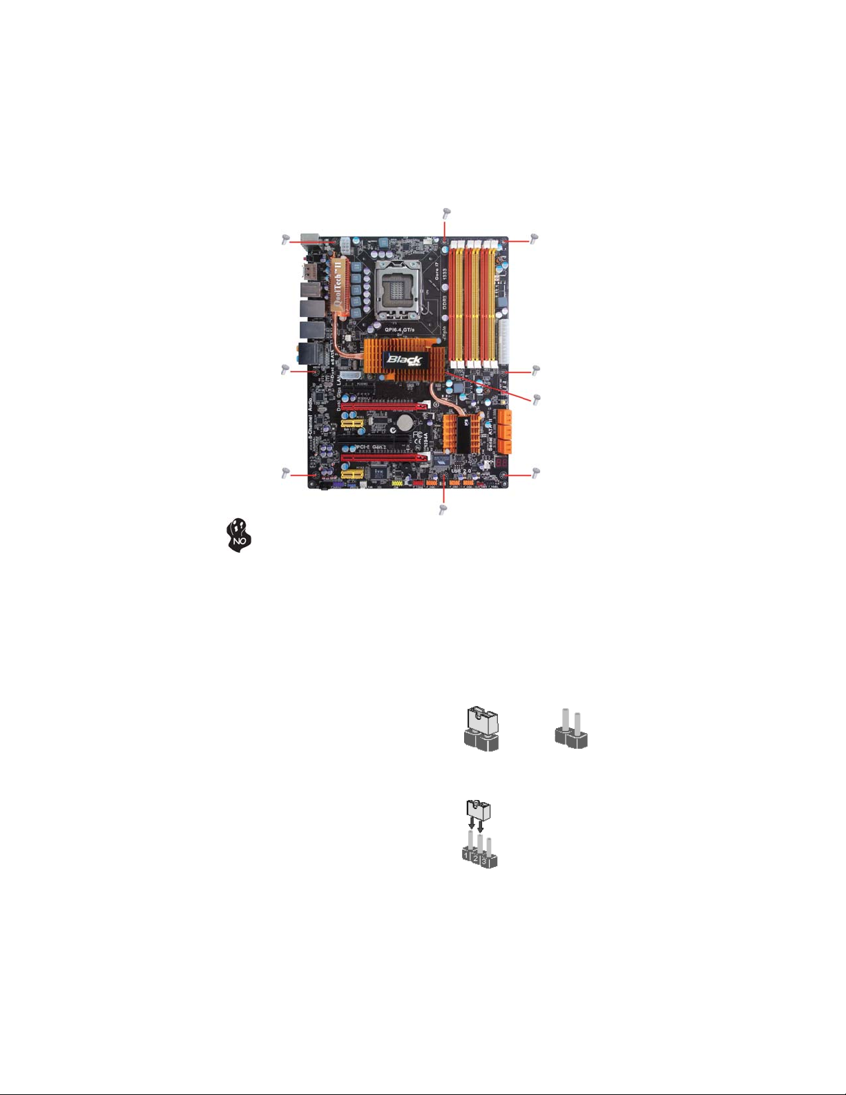
SettingJumpers
Use the motherboard jumpers to set system configuration options. Jumpers with
more than one pin are numbered. When setting the jumpers, ensure that the jumper
caps are placed on the correct pins.
The illustrations show a 2-pin jumper. When
the jumper cap is placed on both pins, the
jumper is SHORT. If you remove the jumper
cap, or place the jumper cap on just one pin,
the jumper is OPEN.
This illustration shows a 3-pin jumper. Pins
1 and 2 are SHORT.
SHORT OPEN
Do not over-tighten the screws as this can stress the motherboard.

9
InstallingtheMotherboard
Checking Jumper Settings
The following illustration shows the location of the motherboard jumpers. Pin 1 is
labeled.
JumperSettings
Jumper Type Description Setting (default)
CLR_CMOS 3-pin Clear CMOS
1-2: NORMAL
2-3: CLEAR CMOS
Before clearing the
CMOS, make sure to
turn off the system.
1
CLR_CMOS
To avoid the system unstability after clearing CMOS, we recommend users
to enter the main BIOS setting page to “Load Default Settings” and then
“Save and Exit Setup”.

10
InstallingtheMotherboard
InstallingHardware
Installing the Processor
Caution: When installing a CPU heatsink and cooling fan make sure that
you DO NOT scratch the motherboard or any of the surface-mount resis-
tors with the clip of the cooling fan. If the clip of the cooling fan scrapes
across the motherboard, you may cause serious damage to the motherboard
or its components.
On most motherboards, there are small surface-mount resistors near the
processor socket, which may be damaged if the cooling fan is carelessly
installed.
Avoid using cooling fans with sharp edges on the fan casing and the clips.
Also, install the cooling fan in a well-lit work area so that you can clearly
see the motherboard and processor socket.
Before installing the Processor
This motherboard automatically determines the CPU clock frequency and system bus
frequency for the processor. You may be able to change the settings in the system
Setup Utility. We strongly recommend that you do not over-clock processors or
other components to run faster than their rated speed.
This motherboard has an LGA1366 socket. When choosing a processor, consider the
performance requirements of the system. Performance is based on the processor
design, the clock speed and system bus frequency of the processor, and the quantity
of internal cache memory and external cache memory.
Warning:
1. Over-clocking components can adversely affect the reliability of the
system and introduce errors into your system. Over-clocking can perma-
nently damage the motherboard by generating excess heat in components
that are run beyond the rated limits.
2. Always remove the AC power by unplugging the power cord from the
power outlet before installing or removing the motherboard or other
hardware components.
Fail-Safe Procedures for Over-clocking
When end-users encounter failure after attempting over-clocking, please take the
following steps to recover from it.
1. Shut down the computer.
2. Press and hold the “Page Up Key (PgUp)” of the keyboard, and then boot the PC
up.
3. Two seconds after the PC boots up, release the “Page Up Key (PgUp)”.
4. The BIOS returns to the default setting by itself.

11
InstallingtheMotherboard
A. Opening of the Load Plate
· Put your thumb on the tail of the load
plate and press the tail down.
· Rotate the load plate to fully open
position.
B. Disengaging of the Load Lever
· Hold the hook of lever and pull it to the
left side to clear retention tab.
· Rotate the load lever to fully open
position.
C. Removing the Cap
· Be careful not to touch the contact at
any time.
D. Inserting the Package
· Grasp the package. Ensure to grasp on
the edge of the substrate.
· Make sure pin 1 indicator is on your
bottom-left side.
· Aimat the socketand place thepackage
carefully into the socket by purely
vertical motion.
E. Closing the Load Plate
· Rotate the load plate onto the package
IHS (Intergraded Heat Spreader).
· Engage the load lever while pressing
down lightly onto the load plate.
· Secure the load lever with the hook
under retention tab.
F. Fasten the cooling fan supporting base
onto the CPU socket on the motherboard.
G. Make sure the CPU fan is plugged to the
CPU fan connector. Please refer to the
CPU cooling fan user’s manual for more
detail installation procedure.
CPU Installation Procedure
The following illustration shows CPU installation components.

12
InstallingtheMotherboard
Installing Memory Modules
This motherboard accommodates four memory modules. It can support six 240-pin
DDR3 1333/1066/800. The total memory capacity is 24 GB.
You must install at least one module in any of the six slots. Each module can be
installed with 4 GB of memory; total memory capacity is 24 GB.
DDR3 SDRAM memory module table
Memory module Memory Bus
DDR3 800 400 MHz
DDR3 1066 533 MHz
DDR3 1333 667 MHz
ff Channel A: DDR3_1, DDR3_2
ff Channel B: DDR3_3, DDR3_4
The six DDR3 memory sockets (DDR3_1, DDR3_2, DDR3_3, DDR3_4, DDR3_5,
DDR3_6) are divided into three channels and each channel has two memory sockets
as following:
ff Channel C: DDR3_5, DDR3_6
1. To achieve better airflow rates and heat dissipation, we suggest that
you use a high quality fan with 3800 rpm at least. CPU fan and
heatsink installation procedures may vary with the type of CPU fan/
heatsink supplied. The form and size of fan/heatsink may also vary.
2. DO NOT remove the CPU cap from the socket before installing a
CPU.
3. Return Material Authorization (RMA) requests will be accepted
only if the motherboard comes with the cap on the LGA1366 socket.
Due to Intel CPU spec definition, the system will not boot if only one
DIMM is installed in DDR3_1, DDR3_3, or DDR3_5. Follow the table
above for recommended memory configuration.
DDR3_1 DDR3_2 DDR3_3 DDR3_4 DDR3_5 DDR3_6
2 DIMMs - Populated - Populated - -
3 DIMMs - Populated - Populated - Populated
4 DIMMs Populated Populated - Populated - Populated
6 DIMMs Populated Populated Populated Populated Populated Populated
Mode Sockets
Recommend memory configuration

13
InstallingtheMotherboard
Do not remove any memory module from its antistatic packaging
until you are ready to install it on the motherboard. Handle the
modules only by their edges. Do not touch the components or metal
parts. Always wear a grounding strap when you handle the modules.
Installation Procedure
Refer to the following to install the memory modules.
1 This motherboard supports unbuffered DDR3 SDRAM .
2 Push the latches on each side of the DIMM slot down.
3 Align the memory module with the slot. The DIMM slots are keyed with
notches and the DIMMs are keyed with cutouts so that they can only be
installed correctly.
4 Check that the cutouts on the DIMM module edge connector match the
notches in the DIMM slot.
5 Install the DIMM module into the slot and press it firmly down until it
seats correctly. The slot latches are levered upwards and latch on to
the edges of the DIMM.
6 Installany remaining DIMM modules.
1. For best performance and compatibility, we recommend that users
give priority to the yellow DIMMs (DDR3_2/DDR3_4/DDR3_6) when
installing DIMMs.
2. We suggest users not mix memory type. It is recommended to use
the same brand and type memory on this motherboard.

14
InstallingtheMotherboard
Table A: DDR3 (memory module) QVL(Qualified Vendor List)
The following DDR3 1333/1066/800 memory modules have been tested and qualified
for use with this motherboard.
Type Size Vendor Module Name
DDR3 800 1 GB HYNIX PC3-6400U-6-00
A-data M3OSS3H3I3120B5Z/Boxed
Aeneon AEH760UD00-10FA98X
Corsair CM3X1024-1066C7/Boxed
Hynix HMT112U6AFP8C-G7N0 AA
Kingston KVR1066D3N7/1G
Micron MT8JTF12864AY-1G1D1
IMSH1GU03A1F1C-10F B2S81427023
IMSH1GU03A1F1C-10G B2S81427034
Gold Bar M378B2873DZ1-CF8 0818
M378B2873DZ1-CF8 0842
Elixir M2F2G64CB8HA4N-BE
HMT125U6AFP8C-G7N0 AA
HYMT125U64ZNF8-G8 AA
Kingston KVR1066D3N7/2G 1.5V 9905403-
006.A00LF
Micron MT16JTF25664AY-1G1D1
IMSH2GU13A1F1C-10F B3S81427044
IMSH2GU13A1F1C-10G B3S81528005
IMSH2GU13A1F1C-13HB3S81124001
Samsung M378B5673DZ1-CF8 0842
4 GB Samsung M378B5273BH1-CF8 0840
Aeneon AXH760UD00-13GA98X
Corsair CM3X1024-1333C9DHX/Boxed
Hynix HMT112U6AFP8C-H9N0 AA
Kingston KVR1333D3N9
Qimonda IMSH1GU13A1F1C-13H
Samsung M378B2873DZ1-CH9
A-DATA M3OSS6H3J4130E1C5Z
Hexon ELPH8AUDR-13M88
Hynix HMT125U6AFP8C-H9N0 AA
Kingston KVR1333D3N9K2/2G
Qimonda IMSH2GU13A1F1C-13H B3S81124001
Samsung M378B5673DZ1-CH9 0842
DDR3 1600 1 GB Kingston KHX12800D3K3/3GX
Hynix
2 GB
DDR3 1066
Qimonda
Qimonda
Samsung
DDR3 1333
2 GB
1 GB
1 GB
Table of contents
Other ECS Motherboard manuals


Popular Motherboard manuals by other brands


Honeywell
Honeywell ST9500C installation instructions

AOpen
AOpen AX45-533 Max Easy installation guide

Advantech
Advantech PCM-5820 Series user manual

MSI
MSI Z270M MORTAR manual

GIGA-BYTE TECHNOLOGY
GIGA-BYTE TECHNOLOGY H410M DS2V V2 user manual

Honeywell Home
Honeywell Home resideo FP134 Installation and user guide