GB GAME RIDER BGB7200 User manual
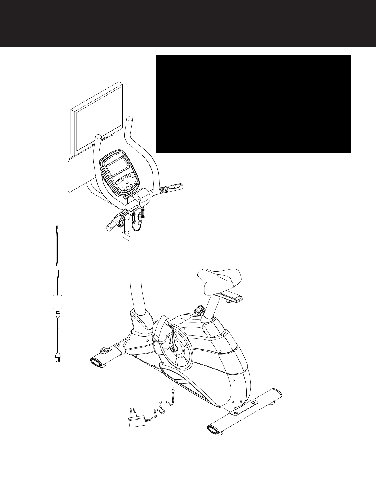
BGB7200 GAME RIDER
OWNER’S MANUAL
* This item is for consumer use only and it is not meant for commercial use.

This page intentionally left blank
General Information
BGB 7200 Page 1
Warranty
Body Flex Sports warrants your product for
a period of 1 year for the frame and 90 days
on all parts if the item is used for the intended
purpose, properly maintained and not used
commercially. Any alterations or incorrect
assembly of the product will void this warranty.
Proof of purchase must be presented for any
warranty validation (no exceptions). This
warranty applies to the original purchaser only
and is not transferable.
This warranty does not cover abuse or defects
caused during use, storage or assembly.
During the warranty period, Body Flex Sports
reserves the right to:
a). provide replacement parts to the
purchaser in an effort to repair the item.
b). repair the product returned to our
warehouse (at the purchaser’s cost).
c). replace the product if neither of the two
previously mentioned actions effect repair.
This warranty does not cover normal wear and
tear on upholstery.
Questions
If you have any questions concerning the
assembly of your item or if any parts are
missing, please DO NOT RETURN THE
ITEM TO THE STORE OR CONTACT THE
RETAILER. Our dedicated customer service
staff can help you with any questions you may
have regarding the assembly of this unit and
can also mail you replacement parts.
Customer Support
Customer Support is open 9:00 a.m. to 5:00
p.m. (Pacific Time) Monday through Friday.
Please contact us by any of the following
means.
Body Flex Sports, Inc.
21717 Ferrero Parkway, Walnut, CA 91789
Telephone: (888) 266 - 6789
Fax: (909) 598 - 6707
Email: info@bodyflexsports.com
Safety
Before you undertake any exercise program,
please be sure to consult with your doctor.
Frequent strenuous exercise should be
approved by your doctor and proper use
of your product is essential. Please read
this manual carefully before commencing
the assembly of your product or starting to
exercise.
• Please keep all children away from this item
when in use. Do not allow children to climb or
play on them when they are not in use.
• Supervise teenagers while they use this unit.
• For your own safety, always ensure that there
is at least 3 feet of free space in all directions
around your product while you are exercising.
• Regularly check to see that all nuts, bolts and
fittings are securely tightened. Periodically
check all moving parts for obvious signs of
wear or damage.
• Clean only with a damp cloth, do not use
solvent cleaners. If you are in any doubt, do
not use your product; contact CUSTOMER
SUPPORT.
• Before use, always ensure that your product
is positioned on a solid, flat surface. If
necessary, use a rubber mat underneath to
reduce the possibility of slipping.
•Always wear appropriate clothing and
footwear such as training shoes when
exercising. Do not wear loose clothing that
could become caught in moving parts during
exercise.
• Do not use this unit if it is not functioning
properly or if it is not fully assembled.
• Do not use this unit for commercial purposes.
Storage and Use
Your product is intended for use in clean
dry conditions. You should avoid storage in
excessively cold or damp places as this may
lead to corrosion and other related problems.
Weight Limit
Your product is suitable for users weighing:
250 pounds or less.
• Before use, you must read and understand all
instructions & warnings stated in this Owner’s
Manual as well as posted on the equipment.
• It is the facility owner’s responsibility to properly
instruct users on the proper operation of the
equipment and to warn them of the potential
hazards.
• If at any time during exercise you feel faint, dizzy
or experience pain, stop and consult your
physician.
Assembling Tools
- Ruler with both metric and English measurements
- 2 x Adjustable Wrenches
- 1 x Philips (”Crosshead”) Screw Driver
Page 2
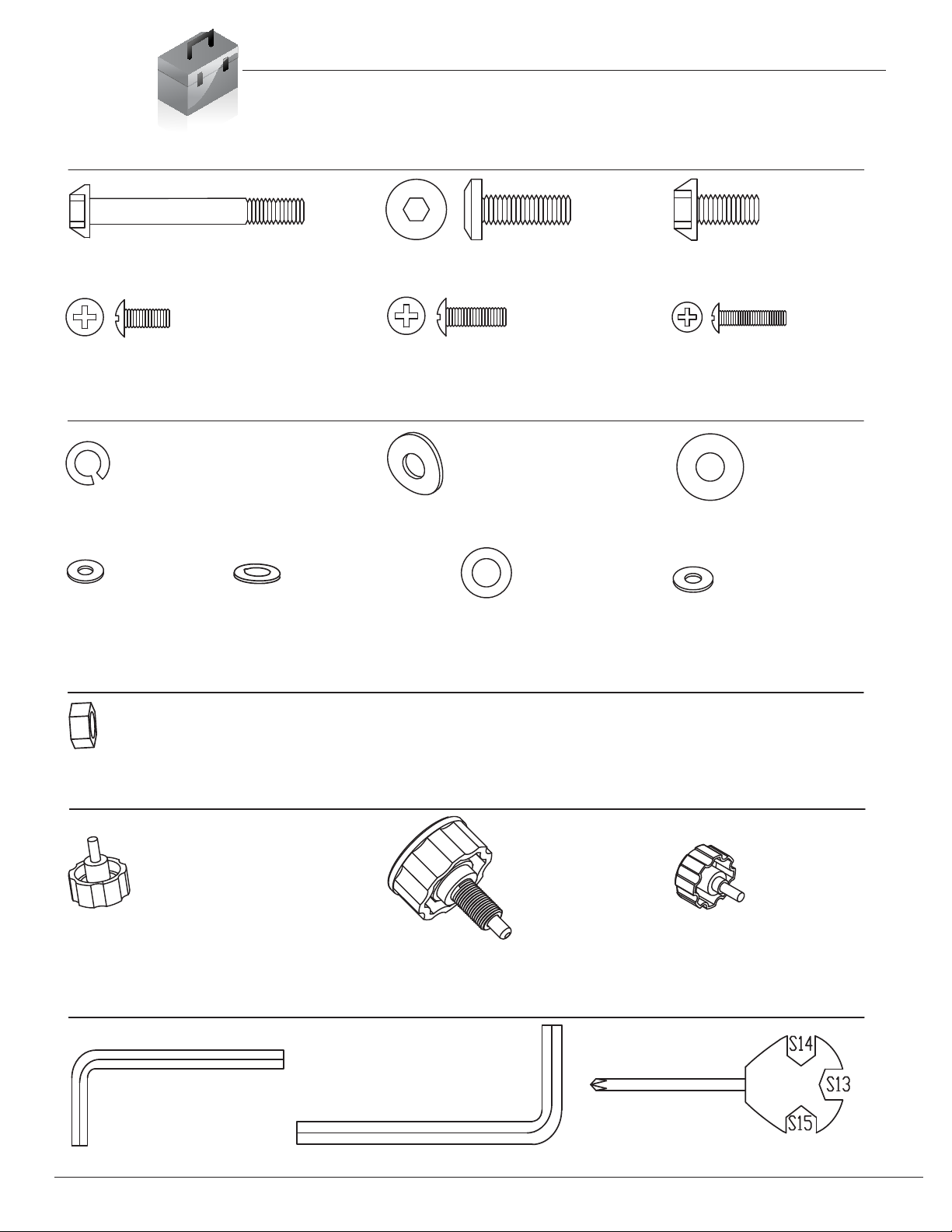
Bolt
Washer
Nut
Tool
#22 Screw (M8x25 mm)
[2 Pieces]
#13 Screw (M8x50 mm)
[4 Pieces]
#26 Screw (M5x16 mm)
[3 Pieces]
#61 Screw (M4x12 mm)
[4 Pieces]
#33 Nut (M8)
[3 Pieces] Pre-assembled
#16 Knob (M8x20 mm)
[1 Piece]
#17 Spring Knob (M16x27 mm)
[1 Piece]
#18 Knob (M8x15 mm)
[1 Piece]
Knob
#28 Arc Washer (M8)
[4 Pieces]
#27 Spring Washer (M8)
[2 Pieces]
#29 Washer (M8, OD20)
[1 Piece]
#63 Tool (S5) #64 Tool (S6) #65 Tool (S13/14/15)
#23 Screw (M8x16 mm)
[4 Pieces]
#25 Screw (M5x10 mm)
[4 Pieces]
#30 Washer (M5)
[4 Pieces]
#59 Washer (M8, OD16)
[4 Pieces]
#62 Washer (M4)
[4 Pieces]
BGB 7200
#32 Washer (M8, OD16)
[3 Pieces]
Pre-assembled
Hardware List
The following hardware is used to assemble your unit. Please take a moment to familiarize yourself with these
items. Please note some of this hardware is already pre-assembled on the machine. Do not be alarmed if you
see parts on this page that are not included in your hardware packet

Page 3
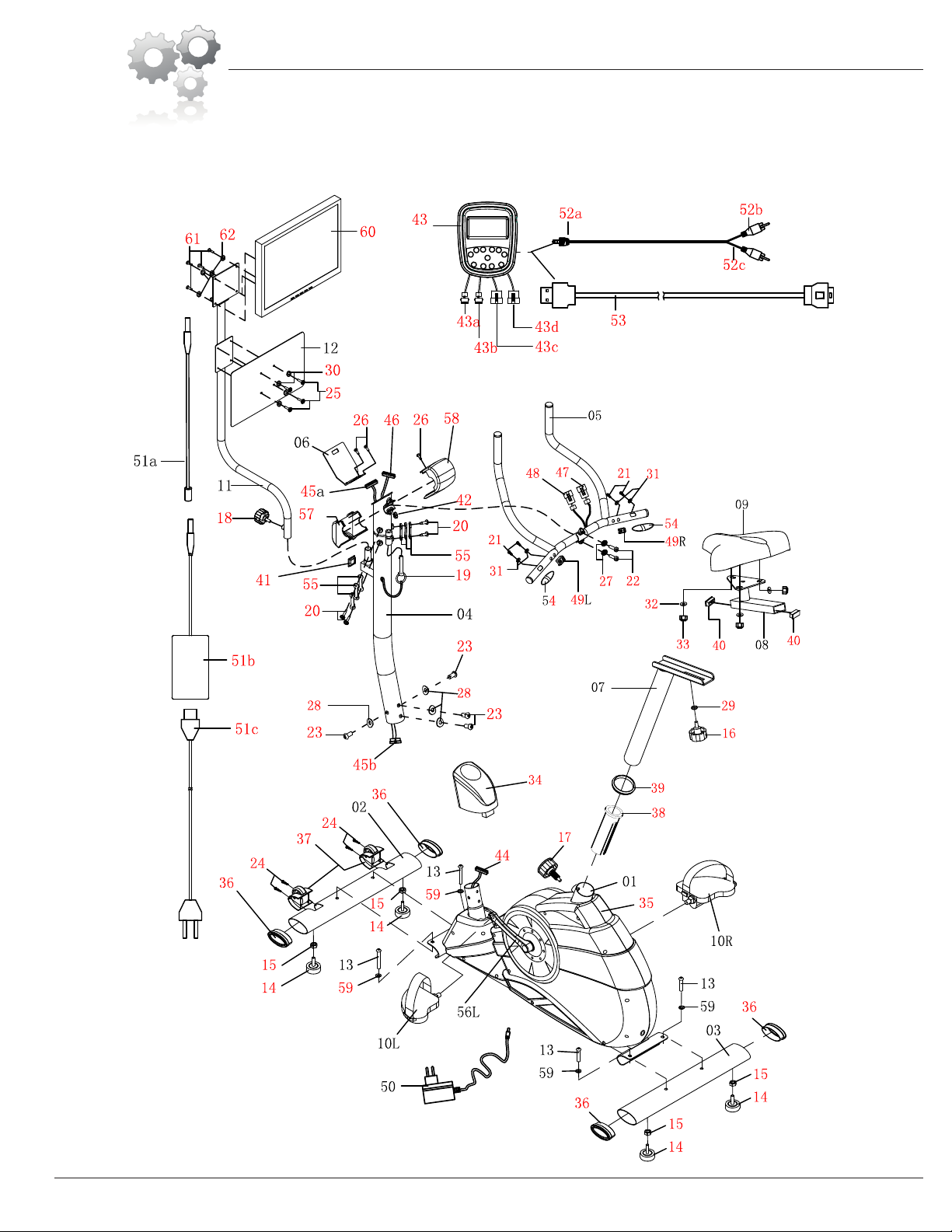
Parts Listing
The following parts list describes all of the parts illustrated on the
exploded diagram on the following page. Please note, most of
these parts are already pre-assembled on your unit.
BGB 7200
# Description # Description
01 Main Frame 38 Bushing
02 Front Stabilizer 39 Rubber Ring
03 Rear Stabilizer 40 Rectangular End Cap (40x20 mm)
04 Center Post 41 Square End Cap (30 mm)
05 Handle Bar 42 Round End Cap
06 Monitor Support Bracket 43 Bike Monitor
07 Seat Post 43a Left Handle Pulse Wire (Upper)
08 Horizontal Seat Bar 43b Right Handle Pulse Wire (Upper)
09 Seat 43c Main Sensor Wire (Upper)
10L Pedal (Left) 43d Handle Sensor Wire (Upper)
10R Pedal (Right) 44 Main Sensor Wire (Lower)
11 Poster Support 45a/b Main Sensor Wire (Middle)
12 Poster Board 46 Handle Sensor Wire (Lower)
13 Screw (M8x50 mm) 47 Left Handle Pulse Wire (Lower)
14 Foot Pad 48 Right Handle Pulse Wire (Lower)
15 Lock Nut (M8) 49L Left Handle Bar Button
16 Knob (M8x20 mm) 49R Right Handle Bar Button
17 Spring Knob (M16x27 mm) 50 AC Adapter for Bike
18 Knob (M8x15 mm) 51a AC Adapter Extension Wire
19 Lock Pin 51b AC Adapter for LCD Screen
20 Screw (M5) 51c Power Wire for LCD Screen
21 Screw (ST4) 52a AV Out Cable (Upper)
22 Screw
(
M8x25 mm
)
52b Audio Cable
(
Lower
)
-White
( )
( )
23 Screw (M8x16 mm) 52c Video Cable (Lower)-Yellow
24 Screw (M4x16 mm) 53 USB Cable
25 Screw (M5x10 mm) 54 Pulse Sensor
26 Screw (M5x16 mm) 55 Resistance Bands
27 Spring Washer (M8) 56L Crank (Left)
28 Arc Washer (M8) 56R Crank (Right)
29 Washer (M8,OD20) 57 Handle Bar Cover (Lower)
30 Washer (M5) 58 Handle Bar Cover (Upper)
31 Washer (M6) 59 Washer (M8, OD16)
32 Washer (M8,OD16) 60 LCD-TV
33 Nut (M8) 61 Screw (M4x12 mm)
34 Center Post Cover 62 Washer (M4)
35 Shroud 63 Tool (S5)
36 End Cap 64 Tool (S6)
37 Wheel Base 65 Tool (S13/14/15)
Page 4
Exploded Diagram
The following diagram is provided to help you familiarize yourself with the parts and
hardware that will be used during the assembly process. Please note that not all of the
parts and hardware you see here will be used while you are assembling the machine
because some of these items are already pre-installed. Please continue to the next
page to begin the assembly process and use this page only as a reference guide for
parts and hardware.
BGB 7200
BGB7200 Page 5
Make sure the wire is hanging out before
proceeding to the next step. If it has fallen
inside the tube, use a bent wire to “fish” it out.
Hardware & Tool Required
Bolt
#13 Screw (M8x50 mm)
[4 Pieces]
Washer
#59 Washer (M8, OD16)
[4 Pieces] #32 Washer (M8, OD16)
[3 Pieces]
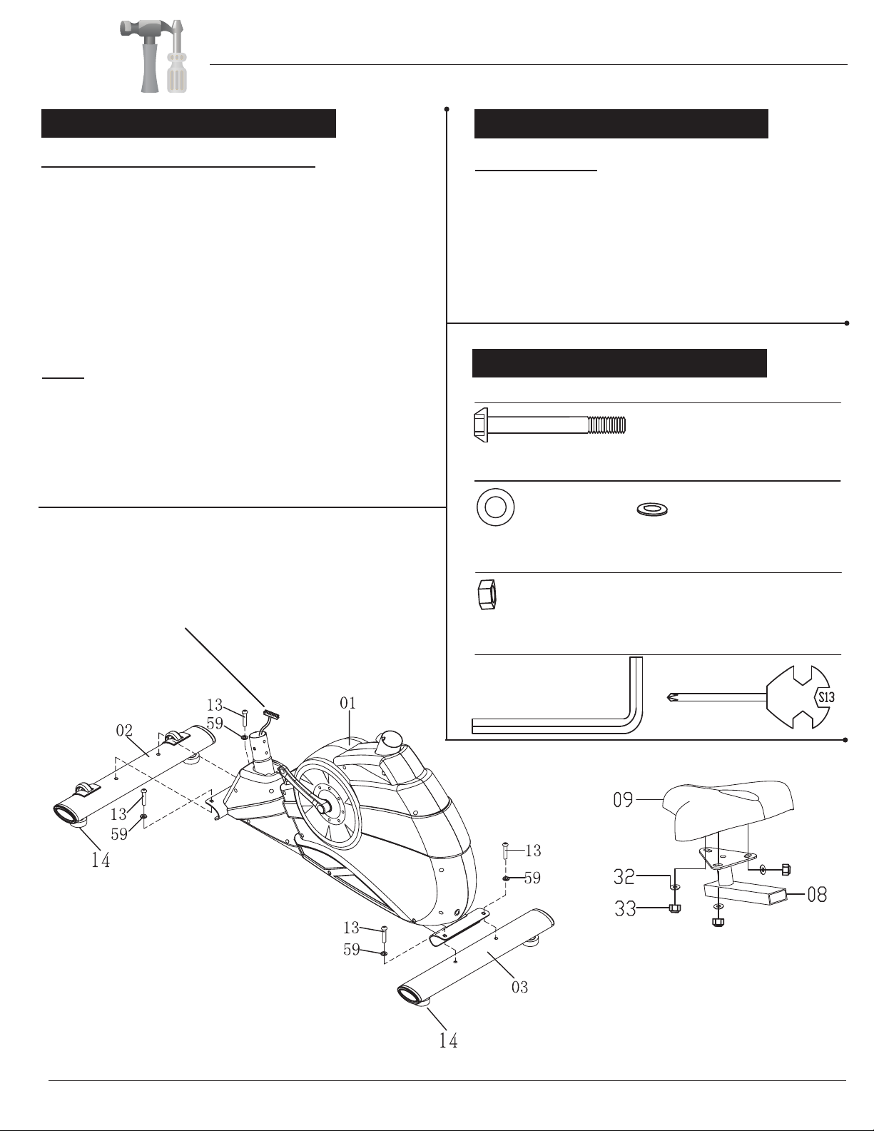
Front & Rear Stabilizer Assembly
With the help of an assistant, attach the Front Stabilizer
(#02) to bracket at the front of Main Frame (#01). Insert two
Screws (#13) through two Washers (#59) followed by the
Main Frame (#01) and Front Stabilizer (#02). Secure them
together by tightening two Screws (#13).
Now attach the Rear Stabilizer (#03) to the bracket at rear
of Main Frame (#01). Insert two Screws (#13) through two
NOTE: The Front Stabilizer (#02) has wheels built in
for ease of relocating and transporting the unit.
The Rear Stabilizer (#03) does not have wheels. Both the
Front Stabilizer (#02) and Rear Stabilizer (#03) have Foot
Pads (#14) for extra stability. Please place an exercise mat
underneath the unit to avoid scratches or marks on the surface
that it rests on.
Washers (#59) followed by the Main Frame (#01) and
Rear Stabilizer (#03). Secure them together by tightening
two Screws (#13).
Nut
Tool
#33 Nut (M8)
[3 Pieces]
#64 Tool (S6) #65 Tool (S13/14/15)
Seat Assembly
Remove the three Washers (#32) and three Nuts (#33)
that are pre-installed on the Seat (#09) as illustrated and
set them aside. Align the holes of the Seat (#09) to the
Horizontal Seat Bar (#08) as shown in the diagram.
Next, secure them together using three Washers (#32)
and threeNuts (#33) that were previously removed.
Assembly Step 2
Assembly Step 1
Assembly Instructions

Page 6
Spring Knob Operation
Turn knob counter-clockwise
three times.
Pull knob outward and adjust
seat simultaneously
Push knob back inward until
it clicks and then tighten it by
turning clockwise.
NOTE:
If labels designating the Left/Right Pedal
are not present, please check pedals
closely for embossed
“L”/ “R” letter marks.
These will be “L” / “R” letters that
are
raised on the pedal material.
W A R N I N G
Do not remove the Seat (#09) for any
reason after you have installed it.
Exercising on this unit without the Seat
(#09) can result in SERIOUS INJURY.
Ensure the seat is locked in place by
tightening the two knobs prior to use.
Assembly Step 3 Hardware & Tool Required
#65 Tool (S13/14/15)
Washer
#29 Washer (M8, OD20)
[1 Piece]
Knob
#17 Spring Knob
(M16x27 mm)
[1 Piece]
#16 Knob (M8x20 mm)
[1 Piece]
Tool
55
40 1 2 3 4
55
40 1 2 3 4
STEP3:
Assembly Instructions
Seat Post Assembly
Pedal Assembly
Screw the
Pedal [Left](#10L) to the Crank [Left] (#56L) by turning
the bolt head on the Pedal [Left](#10L) COUNTER-CLOCKWISE.
Screw the Pedal [Right](#10R) to the Crank [Right] (#56R) by
turning the bolt head on the Pedal [Right](#10R) CLOCKWISE...
A.) Slide the Horizontal Seat Bar (#08) onto the Seat Post (#07) with the
single point of the Seat (#09) pointing toward the front of the unit as
shown in the diagram. Secure by screwing the Knob (#16) through one
Washer (#29), the Seat Post (#07), then the Horizontal Seat Bar
from the handle bars. Please tighten the knob after making an
adjustment, but do not over tighten the knob.
B.) Seat Post (#07) into the mouth of the post that is protruding from the
top of the Main Frame (#01). Please ensure that the hole on the Seat
Post (#07) is facing the same side as the
Spring Knob (#17) so it can
Main Frame (#01). Screw
in the Spring Knob (#17) through the Main Frame (#01) post and
through any hole located on the Seat Post (#07). Please refer to
To use the safety-featured Spring Knob (#17), use one hand to hold
the Seat (#09) to prevent sudden slipping and the other hand to
loosen the knob by turning it counter-clockwise three times as you pull
it outward. Adjust the seat height to your liking and then pop the knob
back in. Then, tighten the knob by turning it clockwise. Please do not
over-tighten.
If the Seat Post (#07) is not already pre-assembled, please insert the
(#08). This knob can be loosened to adjust the distance of the seat
be aligned with the corresponding hole on the
illustration.
BGB 7200
A
B

Page 7
Post (#04) for now.
[Middle] (#45b) to the Main Sensor Wire [Lower] (#44).
Wire Connection
slide the Center Post Cover (#34) onto and up the
Center
Then, connect the Main Sensor Wire
Center Post Assembly
Slide the Center Post (#04) onto the Main Frame (#01)
and secure it using a total of four Arc Washers (#28) and
four Screws (#23).
Center Post Cover
Then, slide down the Center Post Cover (#34).
You may need to rotate it so it fits properly and snugly
over the Main Frame (#01). Please refer to positioning of
the Center Post Cover (#34) in the diagram below.
A s s e m b l y S t e p 4 Hardware & Tool Required
Bolt
#23 Screw (M8x16 mm)
[4 Pieces]
Washer
#28 Arc Washer (M8)
[4 Pieces]
Tool
Remove the Center Post Cover (#34) from packaging and
55
40 1 2 3 4
55
40 1 2 3 4
STEP3:
Assembly Instructions
BGB 7200
#64 Tool (S6)

Assembly Instructions
Assembly Step 5
Hardware & Tool Required
Assembly Step 6
Page 8
Pulse Handle Bar Assembly
Install the Handle Bar (#05) onto the inner side of the
Center Post (#04) using two Screws (#22) and two
Spring Washers (#27) as seen in diagram.
A.Place the Poster Support (#11) onto the corresponding stem
protruding from the Center Post (#04)
. Secure in place using the
Knob (#18) and tighten in place. You can adjust the Poster
Support (#11) location to your preference by securing at the
preferred angle.
B.Affix the Poster Board (#12) onto the lower plate of the Poster
Support (#11) using four Washers (#30) and four Screws (#25).
D.The Poster Board (#12) and Poster Support (#11) are
intended to provide an easy-to-access guide to highlight the key
features and functions of the Game Rider. We suggest placing
the Poster Board (#12) at a 45 degree angle to the user on
either the right or left side.
C.Attached and secure the LCD-TV (#60) to the upper plate of
the Poster Support (#11) using four Washers (#62) and four
Screws (#61).
Bolt
Washer
Tool
#22 Screw (M8x25 mm)
[2 Pieces]
#61 Screw (M4x12 mm)
[4 Pieces]
#25 Screw (M5x10 mm)
[4 Pieces]
BGB 7200
#27 Spring Washer (M8)
[2 Pieces]
#63 Tool (S5)
#65 Tool (S13/14/15)
#30 Washer (M5)
[4 Pieces]
#62 Washer (M4)
[4 Pieces]
#18 Knob (M8x15 mm)
[1 Piece]
Knob
A
B
C
Page 9
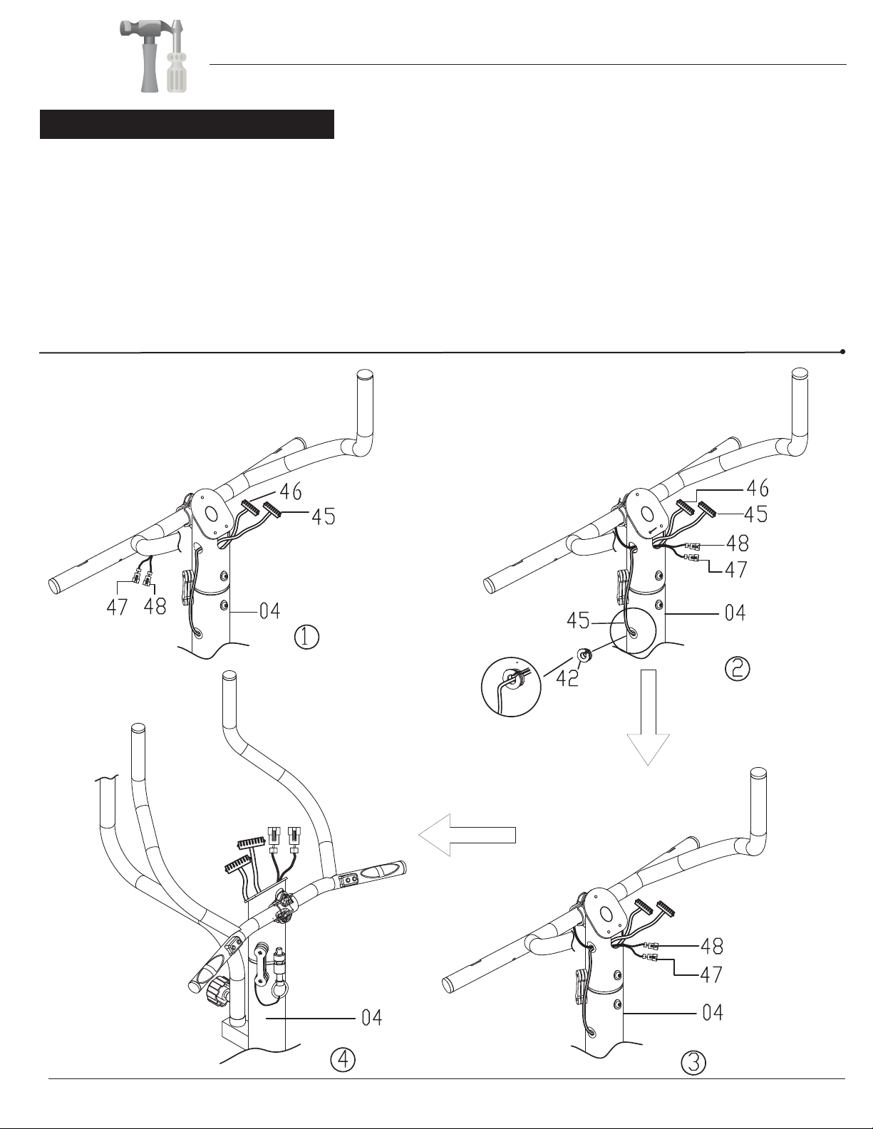
Assembly Step 7
Feed the Left Handle Pulse Wire (#47) and the Right Handle Pulse Wire (#48) through the side hole in
BGB 7200
the neck of the Center Post (#04) and through the front hole of the Center Post (#04) as directed by the
arrow in diagram No. 1. You will need to connect these wires to the Bike Monitor (#43) in later step.
FRONT VIEW
BACK VIEW
Please also ensure that Handle Sensor Wire [Lower] (#46) and Main Sensor Wire [Middle] (#45) are fed
through the same hole as shown in diagram No. 2. Please refer to diagram No. 3 and No. 4 to confirm
proper assembly.
The Round End Cap (#42)i is pre-installed to hold the Left & Right Handle Pulse Wires
(#47 & #48) as
seen in diagram No. 2. However, you may remove the Round End Cap (#42) so you can tuck in the wires
more if there is too much give, or you do not want the wire to hang out so much. If you remove the Round
End Cap (#42), please remember to snap it back in place to hold all the wires in place.
Assembly Instructions

Page 10
Assembly Step 8 Hardware & Tool Required
Bolt
#26 Screw (M5x16 mm)
[2 Pieces]
Tool
Align the holes of the Monitor Support Bracket
(#06) with the holes on the Center Post (#04) as
shown in the diagram. Please ensure that the
wires are free and clear from the bracket. Then,
secure the Monitor Support Bracket (#06) using
two Screws (#26 ).
#42 WASHER FOR M10 BOLT,T2.0 1PC
#42 WASHER FOR M10 BOLT,T2.0 1PC
#42 WASHER FOR M10 BOLT,T2.0 1PC
Assembly Instructions
Wires will fall freely in this step.
You do not and should not need to feed wires
through the Monitor Support Bracket (#26).
BGB 7200

Page 11
Assembly Step 9
BGB 7200
A.Please ensure that the cables connected to the Bike Monitor (#43) are within the track of the backside so they do not get
pinchedor damaged during this next process (please see diagram). Slide the track of the Bike Monitor (#43) halfway onto
the Monitor Support Bracket (#06)
B.Now, connect the corresponding cables as shown in diagram No. 7:
- 43a to 47
- 43b to 48
- 43c to 45a
- 43d to 46
C.Then, carefully place and tuck all the connected cables into Hole B as shown in diagram No. 8.
Please note: 1.) there is room for you to tuck the cables upward and downward in the hollow area of the Center Post (#04)
2.) use care when tucking in cables to avoid injury to your fingers and hands
,
tuck the Wires (#43a/b/c/d) on the Bike Monitor (#43) through Hole A (diagram No. 6),
then slide the Bike Monitor (#43) onto the rest of the track until the monitor locks in place.
Please note: if you need to remove the Bike Monitor (#43), press and hold down the tab on the back of the Bike Monitor (#43)
to unlock, slide, then release the tab.
-Please connect designated wires to matching numbers (i.e. “1” to “1”; “2” to “2”).
NOTE: Wires do not require excessive force to connect; please use care when connecting.
Assembly Instructions
}

Page 12
A s s e m b l y S t e p 10
Hardware & Tool Required
Bolt
#26 Screw (M5x16 mm)
[1 Piece]
Tool
BGB 7200
Place the Handle Bar Cover [Upper] (#58) over the inner side of the Center Post (#04). Please ensure
proper alignment as shown in the diagram. Next, connect the Handle Bar Cover [Lower] (#57) to the
Handle Bar Cover [Upper] (#58). The two covers should fit snugly in place. Secure with one Screw (#26)
through the top of the Handle Bar Cover [Upper] (#58).
The Handle Bar Cover [Lower] (#57) has a small indent for the Main Sensor Wire [Middle] (#45)
to tuck into so that it does not get pinched or damaged when connecting the covers. Please see
"VIEW FROM BOTTOM" diagram below for your reference.
VIEW FROM
BOTTOM
Assembly Instructions
57
26 58
45
57

55
40 1 2 3 4
55
40 1 2 3 4
STEP3:
Page 13
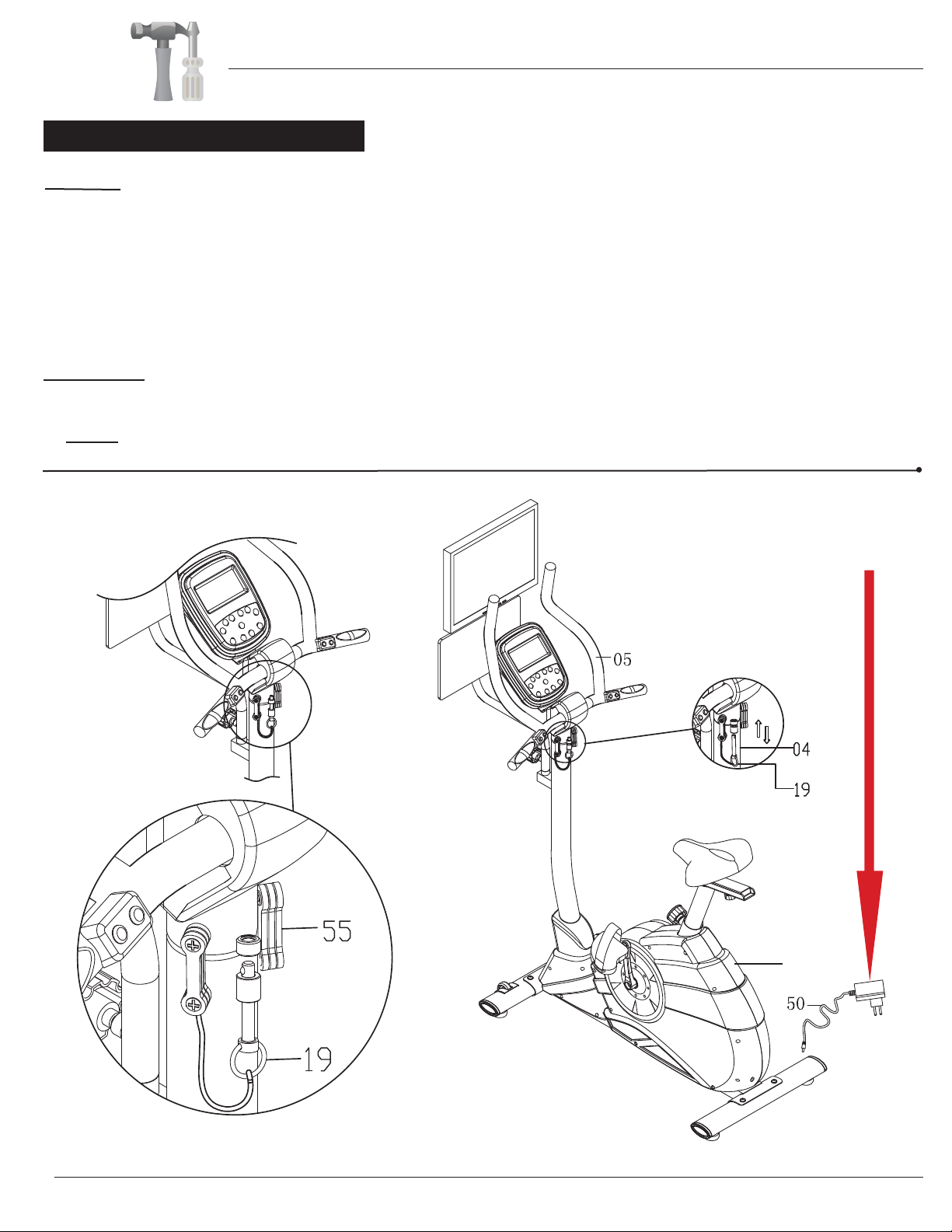
Assembly Step 11
BGB 7200
To Increase Resistance:
1.Increasing the number of bands increases the handlebar
resistance.
2.
If you have lessened resistance, you may increase the resistance
again to a maximum of 3 Resistance Bands (#55). Please follow
the proper “To Reduce Resistance” instructions above when
decreasing resistance. You should only need to ‘add’ the top
portion of the Resistance Band (#55) back to the original
position if these instructions were previously followed.
3.
Please ensure both the left and right sides have the same number
of Resistance Bands (#55) for balanced handlebar resistance.
4.How To Add The (Top of the) Resistance Band:
Method A
Unscrew the upper Screw (#20) only, slip off the upper
hole of the Resistance Band (#55), then screw back
the upper Screw (#20) to its corresponding hole.
Please do not adjust the lower screw or lower portion
of the band (see above “2.”). Please ensure the Screw
(#20) is secure, but do not over-tighten.
Method A
Unscrew the upper Screw (#20) only, slip on the upper hole of the
Resistance Band (#55) onto the Screw (#20), then screw back
the upper Screw (#20) to its corresponding hole. Please do not
adjust the lower screw or lower portion of the band (see above
“2.”). Please ensure the Screw (#20) is secure, but do not over
-tighten.
Method B
Remove the band from the upper Screw (#20) by
pulling downward and stretching the upper hole of the
Resistance Band (#55) to create an initial opening.
Use this opening to stretch the hole of the band to fit
around, over, and off the Screw (#20). The Resistance
Band (#55) should now ‘pivot’ from the lower Screw
(#20). Please do not adjust the lower screw or lower
portion of the band (see above “2.”).
Method B
Add the band to the upper Screw (#20) by placing the upper hole
of the Resistance Band (#55) onto the upper Screw (#20) and
stretch it downward to create an initial opening. Use this opening
to stretch the hole of the band to fit around, over, and onto the
Screw (#20). Please do not adjust the lower screw or lower
portion of the band (see above “2.”).
Method A
If using Method B, you will be adding/reducing Resistance Bands (#55) from the outtermost edges first.
Resistance Bands Installation
The Resistance Bands (#55) add a realistic feel to the interactive game mode and an extra boost of fitness workout to your
arms and upper body. Increasing the number of bands increases the handlebar resistance for a more engaging workout, while
decreasing the number of bands decreases the handlebar resistance and requires less strength to maneuver.
There are (3) three Resistance Bands (#55) on each side pre-installed on the unit (along with the Lock Pin (#19)). This is the
maximum handlebar
resistance you can use on your Game Rider.
To Reduce Resistance:
1.Reducing the number of bands reduces the handlebar
resistance.
2.You need only remove the top of the Resistance Band
(#55). It is not necessary for you to remove the bottom
portion of the band in order to lessen the tension, and
will also prevent the Resistance Band (#55) from
getting lost if not in use.
3.
Please ensure both the left and right sides have the same
number of Resistance Bands (#55) for balanced
handlebar resistance.
4.How To Remove The (Top of the) Resistance Band:
Assembly Instructions
NOTE:
Page 14
NOTE: Your assembly and installation of the bike itself is now complete. However, please continue
reading the remaining sections of this manual in the pages following before you begin using the bike.
Assembly Step 12
Lock Pin
The Lock Pin (#19) allows you to switch the handlebar between fitness bike mode (stationary handlebar) and interactive game
mode (range of motion handlebar).
A.To keep the handle bar stationary:
Align the locking holes and insert the Lock Pin (#19) through the lower hole first followed by the upper hole as shown in the
diagram.
B.To allow range of motion in the handle bar:
Slowly pull the Lock Pin (#19) downward, removing it from the two locking holes.
You may store the Lock Pin (#19) by leaving it the lower Lock Pin hole, or, leave the cord to hang.
AC Adapter
Plug in the AC Adapter for Bike (DC 8V, 1000mA)(#50) male plug into the rear female socket located on the back of the unit
Shroud (#35).
BGB 7200
35
Assembly Instructions

Operation Guide
BGB 7200
This patented Game Rider is not only a Game Bike but also a full-function Programmable Exercise Bike.
• The Game Bike functions are controlled by three major components:
1) the bike; 2) the monitor buttons; and 3) the buttons on the bike handlebar.
• The Programmable Exercise Bike functions are controlled by:
1) the bike; 2) the monitor LCD display & buttons.
There is a “GAME/FIT” button located at the center of the monitor to control the switching between Game Bike
and Programmable Exercise Bike functions.
This Operations Guide will describe the set-up and operation instructions of the Game Bike and Programmable
Exercise Bike functions in separate sections.
NOTE: The Game Rider is a fitness equipment unit that enhances your workouts with the option of
compatibility to your home television set or PC computer. Please consult the proper product manuals for your
home television set or PC computer and confirm that it can safely connect to the features of the Game Rider.
A. Bike & Monitor: Please follow the Assembly Steps described earlier in this manual to assemble the bike
and to attach the television Monitor (#43) to the bike.
B. Connect to TV Set or PC: please follow the instructions on the next page to connect the cables from the
Bike Monitor to the TV Set, or, to the PC.
I. SET UP & CONNECTIONS
[GAME] Mode Operation
Page 15
[GAME] Mode Operation
Page 16
BGB 7200
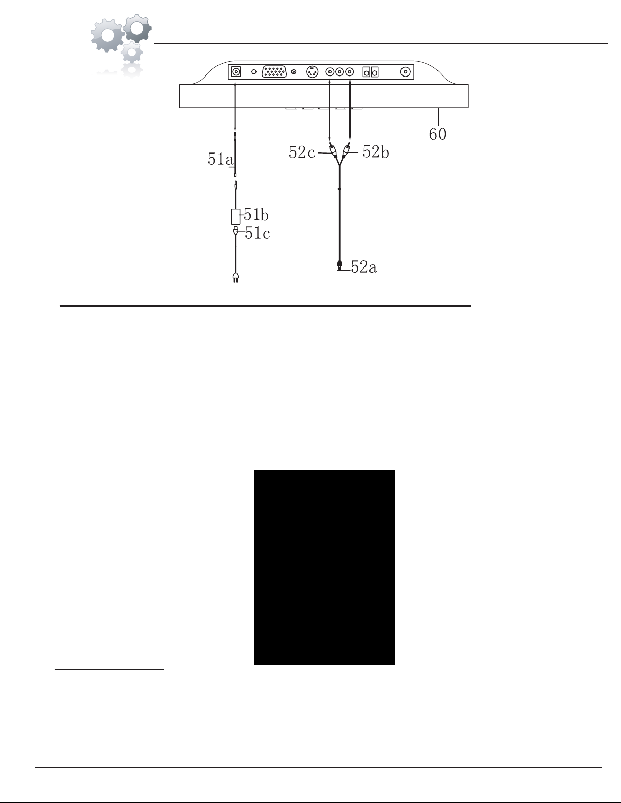
B-1. Connect to LCD TV included with the Game Bike (or to any home TV set):
i. This connection enables user to play the games that are preloaded with the Bike Monitor, and, display the
games on the LCD-TV (#60) that is included with the Game Bike, or, on user’s home TV set (if preferred).
ii. First, connect the single-headed end of the AV Out Cable (#52a) to the AV-OUT port on the Bike Monitor
(#43). Connect the other double-headed end of the Audio/Video Cable (#52b/c) to the corresponding
colors (i.e. yellow to yellow; white to white) while plugging the cables to the ports on the TV.
If you are using the LCD-TV (#60) that is included with the Game Bike, please connect the female head
of the Power Wire for LCD Screen (#51c) to the rectangular box of the AC Adapter for LCD Screen
(#51b). Next, connect the other end of the AC Adapter for LCD Screen (#51b) to the corresponding head of
the AC Adapter Extension Wire (#51a). Continue by plugging in the free end of the AC Adapter Extension
Wire (#51a) into the port on the LCD-TV (#60). Lastly, plug in the free end of the Power Wire for LCD
Screen (#51) into a power source.
iv. POWER CONNECTION:
iii. To prevent bad connection between the Bike Monitor (#43) and LCD-TV (#60) when playing, please
secure the AV cable using the pre-assembled plastic buckle on the back of the Bike Monitor (#43).
To secure the cable, refer to the illustration below and:
1. LIFT the strap so it is free to move from the buckle stopper.
2. SLIDE & PULL the strap fully out of the buckle.
3. PLACE the AV cable within the track of the buckle.
4. TUCK, SLIDE, & PULL the strap back through the buckle.
5. SECURE the AV cable in place and ensure one of the strap notches is secured by the buckle stopper.

[GAME] Mode Operation
Page 17
BGB 7200
B-2. Connect to PC:
i. Alternatively, you may use the bike to play games that are playing on your PC, which include games that
are running directly on your PC, or, games running on Internet web sites.
ii. This connection enables user to play the games that are playing on his/her PC.
iii. First, connect the ‘A-Type’ end of the USB cable (included) to the Bike Monitor (#43).
The ‘B-Type’ end is the flat, rectangular end standard to PC’s.
iv. To prevent bad connection between the Bike Monitor (#43) and PC, please secure the USB cable using the
pre-assembled plastic buckle on the back of the Bike Monitor (#43). To secure the cable, refer to the
illustration below and:
1. LIFT the strap so it is free to move from the buckle stopper.
2. SLIDE & PULL the strap fully out of the buckle.
3. PLACE the USB cable within the track of the buckle.
4. TUCK, SLIDE, & PULL the strap back through the buckle.
5. SECURE the USB cable in place and ensure one of the strap notches is secured by the buckle stopper.
The ‘A-Type’ end is more square in shape.
Then, connect the ‘B-Type’ end of the USB cable to the PC.

Page 1 8
[GAME] Mode Operation
I. Playing Games PRELOADED inside the Wireless Receiver Box:
A. Start-Up Procedure:
A-1. Connect the Bike Monitor (#43) to the TV set: please follow the instructions described in the
“Connect to TV Set ” section above.
A-2. Power ON the TV set, and, use the TV remote controller to select INPUT (usually an “Input” or “AV”
button) to the corresponding AV Input ports (i.e. AV1, AV2, etc.) which you connected the AV Cable.
A-4. Plug in the proper end of the AC Adapter
for Bike (DC 8V, 1000mA)(#50) into the socket located at
the rear end of the bike. Plug in the other end of the AC Adapter to a power source.
A-3. At this point, you should see the Game Menu display on your TV set.
A-5. Press the “GAME/FIT” button on the bike monitor to activate the “GAME ” mode.
a. If you see the below display on monitor (with only the MANUAL option on the top line) after pressing
the “GAME/FIT” button, then, you are in “GAME” mode.
b. However, if you see the below display on monitor after pressing the “GAME/FIT” button, then, you are
in “FITness” mode. Press the “GAME/FIT” button again to switch to the “GAME/FIT” mode.
You are now ready to play the games while exercising on the bike. The gaming visual will be displayed
on your TV screen. Please follow the instructions in the next section to control or manipulate the games.
B. Game Control & Manipulation:
B-1. Buttons on Monitor:
a.There are four buttons (with red icons) on the Monito
r in the zone marked “ GAME SELECT”. These
four buttons are used in selecting different games or options in games.
b.NOTE: these four buttons will function ONLY in “GAME” mode. If you find that these four
buttons do not respond when pressed, please press the “GAME/FIT” button to switch to the “GAME”
mode.
c.Button Functions:
↑ UP key in menu selection.
← LEFT key in menu selection.
→ RIGHT key in menu selection.
:UP
:LEFT
:RIGHT
:EXIT EXIT current selection menu and go to the top menu. Pressing this button in the
middle of playing will EXIT the current game and go to the top menu for
other game selection.
M
M
GAME MODE
FIT(ness) MODE
II. Playing Games PRELOADED in the Bike Monitor:
BGB 7200
If you are using the LCD-TV included with the Game Rider, please refer to the LCD-TV Operations guide
on pg. for this step.
DOWN
-
UP
:DOWN DECREASE the resistance level of the bike during game playing
:UP INCREASE the resistance level of the bike during game playing
Table of contents
Other GB Exercise Bike manuals

Popular Exercise Bike manuals by other brands


Sunny Health & Fitness
Sunny Health & Fitness SF-B121021 user manual

Monark
Monark 827E instruction manual

Stamina
Stamina 1310 owner's manual

American Fitness
American Fitness SPR-BK1072A owner's manual
 Service manual")
Cateye
Cateye CS-1000 (CYCLO SIMULATOR) Service manual

BH FITNESS
BH FITNESS H9158H Instructions for assembly and use