GDS 95/TX User manual

GDS Corp.
2513 Hwy 646 Santa Fe, Texas 77510
409-927-2980 409-927-4180 (Fax) www.gdscorp.com
Operation and Maintenance
Manual
95/TX Wireless Alarm Station & Repeater

95/TX Operation & Maintenance Manual, Revision 1.0
Page 2
CAUTION: FOR SAFETY REASONS THIS EQUIPMENT MUST BE OPERATED AND SERVICED BY QUALIFIED
PERSONNEL ONLY. READ AND UNDERSTAND INSTRUCTION MANUAL COMPLETELY BEFORE OPERATING
OR SERVICING.
ATTENTION: POUR DES RAISONS DE SÉCURITÉ, CET ÉQUIPEMENT DOIT ÊTRE UTILISÉ, ENTRETENU ET
RÉPARÉ UNIQUEMENT PAR UN PERSONNEL QUALIFIÉ. ÉTUDIER LE MANUE D’INSTRUCTIONS EN ENTIER
AVANT D’UTILISER, D’ENTRETENIR OU DE RÉPARER L’ÉQUIPEMENT.
REVISION ISTORY
Revision 1.0 3/1/14 Initial Release
Copyright © 2014 GDS Corp. All Rights Reserved
P/N 1200-0739-01

95/TX Operation & Maintenance Manual, Revision 1.0
Page 3
CONTENTS
1 SAFETY INFORMATION _______________________________________________ 5
FOR YOUR SAFETY __________________________________________________________________ 5
WARRANTY _______________________________________________________________________ 5
IF YOU AVE QUESTIONS ____________________________________________________________ 5
2 GDS CORP WIRELESS SYSTEM OVERVIEW ________________________________ 6
GDS Corp Wireless Devices ___________________________________________________________ 7
Key Features_______________________________________________________________________ 8
3 95/TX HARDWARE ___________________________________________________ 9
4 INSTALLATION _____________________________________________________ 11
Choosing a Location ________________________________________________________________ 11
Power and Signal Wiring ____________________________________________________________ 13
Antenna selection _________________________________________________________________ 14
5 SETUP OPERATION ________________________________________________ 17
User Interface ____________________________________________________________________ 17
Network Setup ____________________________________________________________________ 18
Channel Setup ____________________________________________________________________ 19
Alarm Device Setup ________________________________________________________________ 19
6 TROUBLESHOOTING GUIDE ___________________________________________ 20
7 USER MENUS ______________________________________________________ 21
8 SPECIFICATIONS ____________________________________________________ 26
9 SPARE PARTS ______________________________________________________ 27
10 DRAWINGS AND DIMENSIONS ______________________________________ 28
11 NETWORK SETTINGS ______________________________________________ 31
12 WIRELESS SYSTEM SETUP CHECKLIST _________________________________ 32
13 WIRELESS RANGE CALCULATIONS ____________________________________ 33

95/TX Operation & Maintenance Manual, Revision 1.0
Page 4
TABLE OF FIGURES
FIGURE 2-1: GDS CORP WIRELESS GAS DETECTION SYSTEM .......................................................................... 6
FIGURE 3-1: 95/TX SINGLE ENCLOSURE CONFIGURATION ............................................................................. 9
FIGURE 3-2: 95/TX ALARM STATION / REPEATER WIT LOCAL STROBE & ORN .......................................... 9
FIGURE 3-3: 95/TX ALARM STATION / REPEATER WIT RATED ORN & STROBE ....................................... 10
FIGURE 3-4: 95/TX WIT REMOTE LIG T STACK (PRELIMINARY) ................................................................ 10
FIGURE 4-1: DC POWER INPUT WIRING ....................................................................................................... 13
FIGURE 4-2: AC POWER INPUT WIRING ....................................................................................................... 13
FIGURE 4-3: 95/TX ALARM RELAY CONNECTIONS ........................................................................................ 14
FIGURE 4-4: YAGI DIRECTIONAL ANTENNA .................................................................................................. 15
FIGURE 5-1: 95/TX DISPLAY .......................................................................................................................... 17
FIGURE 7-1: 95/TX MAIN MENU TREE .......................................................................................................... 21
FIGURE 7-2: C ANNEL CONFIGURATION MENU .......................................................................................... 22
FIGURE 7-3: SYSTEM CONFIGURATION MENU ............................................................................................. 23
FIGURE 7-4: COMMUNICATIONS MENU ...................................................................................................... 24
FIGURE 7-5: SYSTEM SECURITY MENU ......................................................................................................... 25
FIGURE 7-6: TEC NICIANS ONLY MENU ....................................................................................................... 25
FIGURE 9-1: 95/TX SPARE PARTS .................................................................................................................. 27
FIGURE 10-1: 95/TX DIMENSIONS (DC, STROBE ONLY) ................................................................................ 28
FIGURE 10-2: 95/TX DIMENSIONS (AC, NR ORN + STROBE) ....................................................................... 29
FIGURE 10-3: 95/TX DIMENSIONS (XP ORN + STROBE) .............................................................................. 30
FIGURE 11-1: GDS CORP NETWORK SETTINGS ............................................................................................. 31
FIGURE 12-1: STEP-BY-STEP WIRELESS SETUP C ECKLIST ............................................................................ 32
FIGURE 13-1: RF TRANSMISSION MARGIN ................................................................................................... 33
FIGURE 13-2: RF TRANSMISSION ZONE ........................................................................................................ 34

95/TX Operation & Maintenance Manual, Revision 1.0
Page 5
1SAFETY INFORMATION
Important – Read Before Installation
Users should have a detailed understanding of 95/TX operating and maintenance instructions. Use the
95/TX only as specified in this manual or detection of gases and the resulting protection provided may be
impaired. Read the following WARNINGS prior to use.
FOR YOUR SAFETY
•The 95/TX wireless alarm station described in this manual must be installed, operated and
maintained in accordance with information contained herein. Installation in any hazardous area
must comply with all applicable restrictions, requirements and guidelines for said hazardous
areas. It is the end user customer’s final decision to ensure that the 95/TX is suitable for the
intended use.
•Do not operate the 95/TX if its enclosure is damaged or cracked or has missing components.
Make sure the cover, internal PCB’s and field wiring are securely in place before applying power.
•Do not expose the 95/TX to electrical shock or continuous severe mechanical shock. Protect the
95/TX and related assemblies from dripping liquids and high power sprays.
•Periodically test for correct operation
•Use only for applications described within this manual.
WARRANTY
GDS Corp. hardware products carry a 2-year limited repair or replacement warranty on electronics and
workmanship. GDS Corp. reserves the right to void warranty claims based on evidence of misuse, abuse,
or the misapplication of a specific sensor in an environment known to adversely affect sensor life.
Warranty period starts on date of shipment from GDS Corp.
IF YOU HAVE QUESTIONS
Please contact us at:
GDS Corp
2513 FM 646 Road North, Santa Fe, Texas, 77510
409-927-2980 (Office), 409-927-4180 (Fax)
info@gdscorp.com
www.gdscorp.com

95/TX Operation & Maintenance Manual, Revision 1.0
Page 6
2GDS CORP WIRELESS SYSTEM OVERVIEW
The new GDS Corp TX-Series wide-area Wireless Gas Detection System incorporates a wealth of new
features and capabilities that make installation, setup and operation easier and faster and provides the
best in wireless personnel safety and equipment protection.
The system consists of a C2/TX Wireless Site Manager 32-point controller with WiFi, MODBUS satellite or
cellular connectivity, one or more GASMAX/TX single or dual channel battery-operated wireless gas
detectors for toxic and combustible gases and one or more 95/TX Wireless Alarm Station / Repeaters that
allow highly visible strobes or horns to be placed in locations such as gates, guard shacks or worker’s
quarters where timely indication of hazardous conditions can reduce injuries or save lives.
Figure 2-1: GDS Corp Wireless Gas Detection System
GM/TX W reless Gas Mon tors
C2/TX W reless
S te Manager
w th Data Logg ng
95/TX W reless Alarm Stat ons
Remote MODBUS Master
Wired or Wireless Link
Local WiFi
Network to
Smartphones or
Tablets
Satellite or Cell lar
Remote Monitoring
Worldwide
Text Alarms & Alerts
via Smartphone
Network Website
Dashboard Monitor

95/TX Operation & Maintenance Manual, Revision 1.0
Page 7
ALARM
STATUS
CLEAR
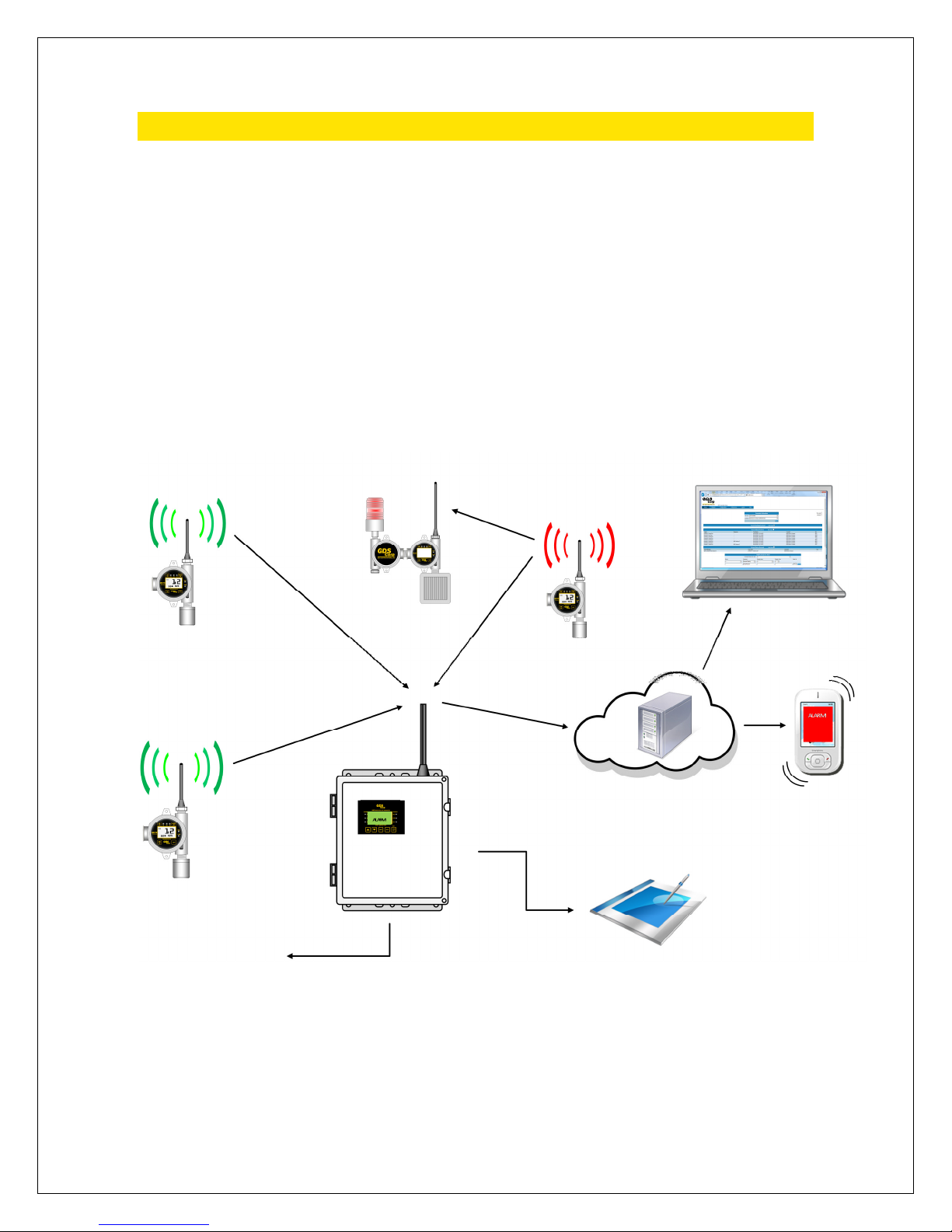
GDS CORP WIRELESS DEVICES
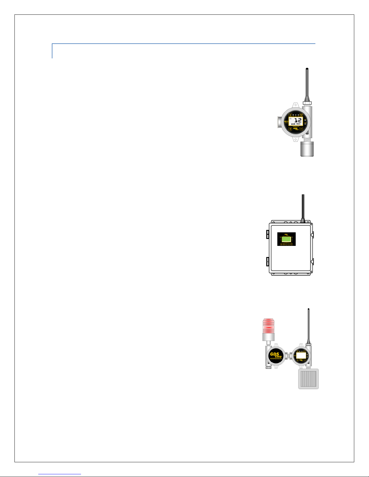
GASMAX/TX GAS MONITOR (GM/TX)
The battery-powered single or dual channel GASMAX/TX monitor uses the latest in ultra-
low power infrared or electrochemical sensors to sample the ambient air every six
seconds for toxic or combustibles gases. If gas is present, a gas data packet containing
level and alarm data is transmitted to any active listener device. A user programmable
‘wake-up timer’ guarantees that even if gas is not present, a transmission will occur on
predetermined intervals to notify the C2/TX controller that the detector is present and
working. For more information on the GASMAX/TX monitor see the GASMAX/TX Users
G ide (P/N 1200-0863).
C2/TX WIRELESS SITE MANGER (C2/TX)
The C2/TX Wireless Site Manager listens for broadcast gas data packets and verifies that
transmissions are being received from all active channels. If an alarm condition exists,
the C2/TX activates local warning devices and updates its MODBUS database. An
optional cellular or satellite remote access system reads changes in the MODBUS
database and transmits alarm information to a cloud server which, in turn, sends
text messages or email warnings and alerts. The C2/TX also acts as the Beacon
Server for the entire system, transmitting a broadcast signal that all radios use to
synchronize their transmissions. For more information on the C2/TX Wireless Site
Manager, see the C2/TX Users G ide (P/N 1200-0866).
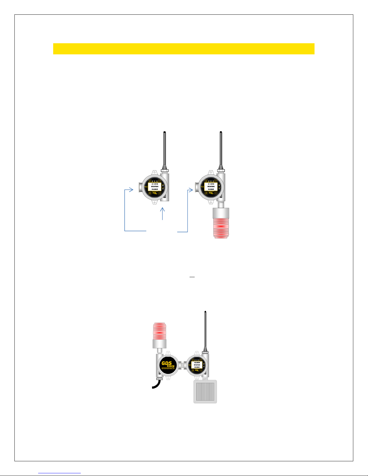
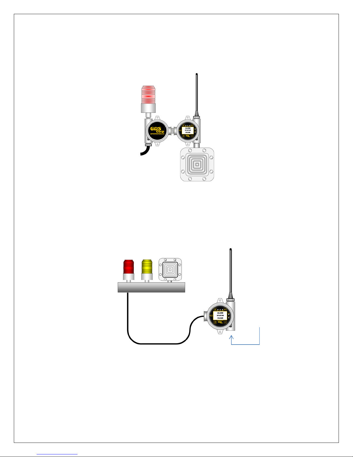
95/TX WIRELESS ALARM STATION (95/TX)
The 95/TX Wireless Alarm Station also listens for gas data packets broadcast by
GASMAX/TX monitors and activates local horns or strobes if an alarm condition
exists. In addition, the 95/TX can also be programmed to retransmit (“repeat”)
each received gas data packet. Finally, if required by network topology, a 95/TX
alarm station can be programmed to act as the Beacon Server for the network.
This might be appropriate if the 95/TX is mounted on a pole or other ‘high point’
that provides better line-of-sight communications with all GASMAX/TX monitors,
C2/TX controllers and other 95/TX alarm stations. This man al contains information on the 95/TX
Wireless Alarm Station.

95/TX Operation & Maintenance Manual, Revision 1.0
Page 8
KEY FEATURES
BATTERY-POWERED COMBUSTIBLE MONITORS
In addition to standard low-power electrochemical sensors, the new GASMAX/TX supports an ultra-low
power infrared detector for methane, propane, general hydrocarbons as well as carbon dioxide gas. Dual-
channel GASMAX/TX monitors can be configured to measure both combustible and toxic hydrogen sulfide
gases with no external source of power.
LISTENER DEVICE AUTO-CONFIGURATION
Each GASMAX/TX gas monitor periodically broadcasts a config data packet that contains information on
tag name, engineering units, zero and span values, alarm levels and other user-adjustable settings. When
a C2/TX site manager or 95/TX alarm station receives a config data packet, setup information in the
GASMAX/TX is automatically loaded into the listener’s channel information database. This makes it
unnecessary to independently program listener devices, and allows them to announce alarms using
customer-recognizable tag names such as “North Fence” or “Drillers Shack” previously programmed into
the individual GASMAX/TX monitor.
REMOTE ACCESS
The C2/TX Wireless Site Manager can be optionally configured for satellite or cellular remote access
packages. These packages include a dedicated satellite or cellular modem with optional GPS receiver,
antenna cable, lightning arrestor and antenna, and are custom programmed to query the C2/TX Modbus
database and transmit alarm and event data to network-based servers that display the information on a
“dashboard” display. Users can setup the dashboard to automatically generate emails, text messages or
cellular phone calls in the event of a gas alarm or maintenance event.
ADVANCED RF TECHNOLOGY
GDS Corp wireless products use 900 M z or 2.4 G z RF modems based on Frequency opping Spread
Spectrum (F SS) technology. F SS radios offers longer range and higher power than those found in typical
mesh networks. In the United States, Canada and selected other countries, 900 M z is recommended due
to increased power output available (up to 1 watt), greater range and ability of lower frequency signals to
travel around interfering objects. Systems utilizing 2.4 G z are license-free in most areas of the world and
tend to be less susceptible to interference from existing radio frequency sources.

95/TX Operation & Maintenance Manual, Revision 1.0
Page 9
395/TX HARDWARE
The GDS Corp 95/TX Wireless Alarm Station is available in a number of different configurations that
include rated and non-rated horns and strobes as well as remote two, three or four strobe light stacks
with optional horn sounder. Dimensions and mounting recommendations are shown in Appendix X.
The 95/TX repeater-only or repeater plus strobe configuration includes a single NEMA 7 enclosure as
shown in Fig 3-1. DC input power can range from +12 to +30VDC.
Figure 3-1: 95/TX Single Enclosure Configuration
If the 95/TX configuration includes an AC power supply or horn sounder, the device is configured using
two NEMA 7 enclosures as shown in Fig 3-2. The optional AC power supply is located in the left-side
enclosure. Input power is limited to +12VDC, +24VDC or 110/220VAC only.
F gure 3-2: 95/TX Alarm Stat on / Repeater w th Local Strobe & Horn
95/TX
configured for
repeater
function only
(+12-30 VDC)
95/TX configured
for repeater with
local strobe
(+12-30 VDC)
DC Power
Input
AC or DC
Power Input
95/TX
configured
with local NR
strobe and
horn
(+12 VDC,
+24 VDC or
110/220 VAC)
Strobe colors
include:
RED
YELLOW
BLUE
PURPLE
Strobe colors
include:
RED
YELLOW
BLUE
PURPLE

95/TX Operation & Maintenance Manual, Revision 1.0
Page 10
Figure 3-3 shows the same configuration with Class 1 Division 2 rated strobe and Class 1 Division 2 rated
horn. Input power is limited to +12VDC, +24VDC or 110/220VAC only.
F gure 3-3: 95/TX Alarm Stat on / Repeater w th Rated Horn & Strobe
The 95/TX Alarm Station / Repeater is also available with remote two strobe, two strobe plus horn, three
strobe and three strobe plus horn combinations (See Figure 3-4). Contact GDS Corp for more details.
F gure 3-4: 95/TX w th Remote L ght Stack (Prel m nary)
AC or DC
Power Input
DC Power
Input
95/TX configured
with local rated
strobe and horn
(+12 VDC,
+24 VDC or
110/220 VAC)
Strobe colors
include:
RED
YELLOW
BLUE
PURPLE
Strobe colors
include:
RED
YELLOW
BLUE
PURPLE

95/TX Operation & Maintenance Manual, Revision 1.0
Page 11
4INSTALLATION
CHOOSING A LOCATION
The most important role of an Alarm Station is to provide real-time
warning of hazardous conditions that may be present in the vicinity.
As a result, it is important to install the 95/TX s ch that the strobe
and/or warning horn provide maxim m coverage for the warning area.
At the same time, consideration must be given to the following
conditions: 1) ability to receive gas data packets from all GASMAX/TX
wireless gas detectors; 2) access to a continuous source of AC or DC
power, and 3) maintaining a minimum distance between the antenna
and closest metallic object, or any object that creates RF interference
s ch as high voltage power lines or large sodi m or merc ry vapor
lamps. The minimum spacing distance is determined by the RF
frequency chosen and is shown below.
MOUNTING THE 95/TX (S ngle Enclosure)
The 95/TX standard enclosure is a single cast aluminum explosion-proof
(NEMA 7) enclosure that has two 0.27” diameter mounting holes spaced
5.0” apart. If a local strobe is attached, the strobe body extends 0.5”
behind the plane of the enclosure. If the 95/TX is to be mounted on a flat
plate, then spacers must be installed between the enclosure mounting
holes and the plate to allow for clearance between the strobe and
backplate. Furthermore, if the 95/TX is plate-mounted, the plate should
be designed such that the antenna extends above the plate into free
space. Power to the unit should be brought through the left-hand side
¾” NPT threaded opening using an appropriate fitting (not provided).
For pole mount applications, GDS Corp offers a pole mounting kit
(P/N 20-0165) that contains a pre-drilled plate, stainless steel mounting
bolts and two stainless steel U-bolt assemblies. The pole mounting kit
supports poles up to 2.0” in diameter.
Distance from antenna to
nearest metallic surface:
900 M z => 24” Minimum
2.4 G z => 6” Minimum
Distance above ground:
6’ / 2m recommended
5.0”
9.5”

95/TX Operation & Maintenance Manual, Revision 1.0
Page 12
In all cases, the 95/TX enclosure must be properly connected to earth
ground to maximize radio reception and as protection against electrical
discharge and lightning strikes.
MOUNTING THE 95/TX (Dual Enclosure)
If the 95/TX configuration includes either a horn or AC power supply,
the unit consists of two enclosures mounted side by side as shown at
right. There are four 0.27” diameter mounting holes spaced as shown.
The optional AC supply is always mounted in the left-hand side
enclosure and AC or DC power enters through the lower left side ¾”
NPT threaded opening using an appropriate fitting (not provided).
Both the horn and strobe extend rearward past the plane of the
mounting holes by 0.5” so if the unit is to be plate mounted, then
appropriate spacers must be installed between the enclosure
mounting holes and plate to allow for clearance between the
backplate and strobe and horn. If mo nting the nit on a plate, be s re
that the antenna extends above the plate into free space.
The dual-enclosure unit can also be mounted using the
p/n 20-0165 pole-mounting kit as shown at right. For best
protection against lightning or electrical discharge, make
sure the pole is buried at least 3’ into the ground or is
properly bonded to earth ground using large diameter
wire or braided cable. If the pole extends above the level
of the antenna as shown, the pole will provide some
additional protection against direct lightning strikes.
5.0”
6.0”
17”

95/TX Operation & Maintenance Manual, Revision 1.0
Page 13
POWER AND SIGNAL WIRING
DC POWER
When using a source of 24VDC, the power and ground connections are made to the right-hand side
terminal block (TB1) on the 95/TX I/O power supply board located in the back of the enclosure.
F gure 4-1: DC Power Input W r ng
AC POWER
When using a source of AC power, the line, neutral and earth ground connections are made to AC power
supply located in the left-hand side enclosure. A cable gland is provided to run the power wiring out the
lower left side enclosure opening.
F gure 4-2: AC Power Input W r ng
-
+12-30 VDC Input
TB1
Line
Neutral
Ground

95/TX Operation & Maintenance Manual, Revision 1.0
Page 14
CONNECTING ALARM DEVICES
The 95/TX provides three SPDT alarm relay outputs and one dedicated fault relay output. Terminals are
labeled “NO” (normally open), “NC” (normally closed) and “C” (common) and are located on the power
supply board located in the back of the enclosure. The power supply board also provides contacts for a
remote “alarm acknowledge” button. Power for 24V strobes or horns can be taken from spare “+” and “-“
pins on TB1.
F gure 4-3: 95/TX Alarm Relay Connect ons
ANTENNA SELECTION
MONOPOLE AND COLLINEAR OMNI-DIRECTIONAL ANTENNAS
The 95/TX Wireless Alarm Station includes a standard “rubber duck” omnidirectional antenna. “Omni”
antennas are the most commonly used antenna for portable and semi-portable equipment. When
mounted vertically, they provide good all-around (“omnidirectional”) reception and transmission from
horizontal directions, and are generally rugged and when sealed properly against moisture can provide
years of quality service.
The 95/TX is also available with a flexible omnidirectional antenna that is more resistant to damage in
field applications. The flexible antenna offers the same gain and reception pattern.
Collinear antennas are similar in appearance to ‘rubber duck’ antennas, but are more sophisticated and
combine several vertical antennas that operate in parallel to increase signal gain by focusing the reception
pattern in a more horizontal plane. Collinear antennas should be used where additional signal gain is
required.
Fault Relay
Relay 3
Relay 2
Relay 1

95/TX Operation & Maintenance Manual, Revision 1.0
Page 15
YAGI DIRECTIONAL ANTENNAS
Yagi antennas are directional along the central beam of the antenna. The folded element is towards the
back and the antenna should be “pointed” in the direction of the transmission. Yagi antennas should also
be mounted with at least 2-3’ of clearance from other objects. Mount the Yagi antenna as shown for
maximum RF transfer.
Figure 4-4: Yagi Directional Antenna
In networks spread over wide areas, it is common for a central receiver / controller to have an omni-
directional antenna (such as a collinear) and the remote GAMAX/TX monitor to have Yagi directional
antennas. Care should to be taken to ensure the Yagi is aligned correctly to achieve optimum
performance.
COAXIAL CABLES
When installing a coaxial cable between the 95/TX and a remote antenna, constructing a loop of cable
below the antenna is always recommended. The loop allows water to drip off the bottom of the U
instead of into the connection, reduces installation strain and provides spare cable length in case later the
original connectors need to be replaced.
Avoid installing coax cables together in long parallel paths. Leakage from one cable to another has a
similar effect as mounting an antenna near another antenna.
SURGE PROTECTION & GROUNDING
Voltage surges primarily enter the 95/TX Alarm Station via the antenna connection as a result of electrical
discharge in the atmosphere. Electrical energy follows the most direct path to earth and the best
protection is achieved by “draining” the surge energy to earth via an effective earth ground. Wireless
Always mount Yagi antennas with the
primary elements or ented n the same
d rect on as any omnidirectional
antennas in the same system

95/TX Operation & Maintenance Manual, Revision 1.0
Page 16
devices should have a solid connection to earth via a ground stake or ground grid if the soil has poor
conductivity. Solid connection means a large capacity conductor (not a small wire) with no coils or sharp
bends. All other devices connected to the 95/TX, such as remote strobes or horns, should be grounded to
the same ground point if possible. There can be significant resistance between different ground points
leading to very large voltage differences during lightning activity.
It is very difficult to protect against direct lightning strikes but the probability of a direct strike at any one
location is very small. Unfortunately, power line surges and electromagnetic energy in the air can induce
high voltage surges from lightning activity several miles away.
SEALING ANTENNA AND CABLE FITTINGS
If a coax cable connects to the antenna via connectors, it is very important to weatherproof the
connection using #1000-2314 or equivalent sealing tape. Moisture ingress into a coax cable connection is
the most common cause of problems with antenna installations. A three layer sealing process is
recommended – an initial layer of electrical PVC tape, followed by a second layer of self-vulcanizing
weatherproofing tape (#1000-2314), with a final layer of electrical PVC tape.
USE IN HAZARDOUS AREAS
The 95/TX enclosure is certified for use in Class 1 Division 1 hazardous areas. The standard 10-0295
antenna coupler is designed to meet Class I Division 2 hazardous area standards but is not 3
rd
party
certified.

95/TX Operation & Maintenance Manual, Revision 1.0
Page 17
5SETUP & OPERATION
USER INTERFACE
There are four magnetic switches on the face of the 95/TX, arranged in a quadrant around the LCD
display labeled “NEXT”, “EDIT”, “DOWN/TEST” and “UP/ACK”. To activate, or “press” a magnetic switch,
swipe the magnet near the switch. To access the Main Menu, press the “EDIT” key. While in the menu
display, use the UP and DOWN keys to select an item, EDIT to change an item, and NEXT to exit the menu.
NOTE: OLDING A MAGNET OVER T E DN/TEST KEY WILL ACTIVATE (TEST) ALL ALARM RELAYS
When power is applied to the 95/TX, the display will show one of two messages – “Alarm Status Clear” if
the 95/TX has identified and locked onto the network beacon, or “No Server Found”, indicating that the
beacon signal is either too weak OR the network selection (“A” through “Z”) is not programmed to match
the current network.
F gure 5-1: 95/TX D splay
Once programming is complete and the beacon server is ‘in range’, the “Alarm Status Clear’ message will
be displayed until an alarm event occurs. This includes both gas alarms as well as communications errors
caused by missing gas data packet information.
An icon on the right-hand side of the screen indicates the status of the beacon server and can be useful
when troubleshooting network issues:
Beacon in Range
Normal Operation
Beacon Not in Range
Check network settings
Beacon In Range but
was previously lost:
Intermittent beacon
signal; check network
S
E
R
V
E
R
95/TX configured
as only network
beacon server

95/TX Operation & Maintenance Manual, Revision 1.0
Page 18
NETWORK SETUP
Integrating the 95/TX Wireless Alarm Station into a GDS Corp network requires adjustment of the
following network device settings. Systems shipped from GDS Corp will already have these settings pre-
programmed.
NETWORK ID
All devices on a single GDS Corp wireless network must share the same Network ID. The Network ID
parameter combines the definition of a unique “System ID”, the selection of a set of operating
frequencies and the use (or not) of data encryption algorithms when transmitting and receiving data. See
Chapter 12 for a complete definition of network parameters defined by each Network ID. Data
transmission on networks “A” through “L” are non-encrypted, while data transmission on networks “M”
through “Z” are encrypted in software. There is no performance penalty associated with an encrypted
network selection.
To select the Network ID, press “EDIT” to access the main menu, and then select “Communications” and
“Network ID”. If the selected Network ID matches that programmed into the primary Beacon Server, the
“Alarm Status Clear” message will appear.
RF MODE
Mode determines if the 95/TX is defined as the “Beacon Server”. In any GDS Corp network, one device
acts as the beacon server, transmitting a continuous signal that allows each wireless device to synchronize
its own transmission while minimizing power consumption. If the 95/TX is set for “Client”, then no beacon
is transmitted; if set for “Server”, the 95/TX will broadcast the beacon signal.
NOTE: ONLY ONE DEVICE IN ANY GIVEN NETWORK S OULD BE PROGRAMMED AS T E BEACON SERVER.
In some cases, it may be advantageous for a 95/TX to act as the beacon server, if the C2/TX controller is
mounted inside a building or structure and the 95/TX alarm station is mounted outside and above ground
level. In this case, a beacon transmitted by the 95/TX may have a better chance of reaching the remote
GASMAX/TX monitors. In this case, be sure that the C2/TX Client/Server setting is set to “Client”.
To select Client or Server, press “EDIT” to access the main menu, and then select “Communications” and
“RF Mode”. Remember, only one device in any given network should be set as the “Beacon Server”.

95/TX Operation & Maintenance Manual, Revision 1.0
Page 19
RF POWER
Systems that operate on 900 M z offer adjustable power levels, from 10 mW up to 1.0 Watt. Unless there
are other GASMAX/TX monitors located in close proximity to the 95/TX, GDS Corp recommends setting
the power level to 1.0 Watt.
To select the power level, press “EDIT” to access the main menu, and then select “Communications” and
“TX Power”. Power levels in systems that utilize 2.4 G z radios cannot be adjusted.
CHANNEL SETUP
The next step after the 95/TX is successfully integrated into the wireless network is to setup the total
number of active channels and enable individual channels assigned to each remote GASMAX/TX gas
monitor.
ACTIVE CHANNELS
Set the total number of channels (From “1” to “32”) that the 95/TX needs to monitor by selecting “Edit”
followed by “System Config” and then “Active Channels”. Press “EDIT” to modify the setting.
INDIVIDUAL CHANNEL SETUP
Once the total number of channels is set, activate each channel that will be associated with an individual
GASMAX/TX gas monitor. You will need to know the Remote ID of each GASMAX/TX monitor. Dual
channel devices will have two device ID settings; this will allow the 95/TX to individually monitor and
alarm on each channel separately.
For each monitored channel, the 95/TX can be programmed to “repeat”, or re-broadcast each received
gas data packet. This is useful if the 95/TX is located between the GASMAX/TX monitor and C2/TX
controller, or if the gas data packet needs to be repeated to other 95/TX alarm stations located in remote
areas.
To enable a specific channel and set the Device ID and Repeat Packet parameters, press “EDIT” followed
by “Channel Config”.
ALARM DEVICE SETUP
Once the network and channel parameters are set properly, program each relay to activate based on
alarm data from specific channels. For more information on relay setup, see the User Menu section on
relays.
To program each relay, press “EDIT”, followed by “System Config” and then select “Relay Config”.

95/TX Operation & Maintenance Manual, Revision 1.0
Page 20
6TROUBLESHOOTING GUIDE
DISPLAY SCREEN SHOWS “NO SERVER FOUND”
•95/TX located too far from beacon server; move closer
•95/TX network ID not set to match network ID of primary beacon server; match Network IDs
•95/TX antenna or antenna cable broken or damaged; repair or replace
•Radio type incorrect (using 900 M z radio in 2.4 G z network or vice-versa)
IN-RANGE ICON SHOWS DOTTED LINE
•Beacon server signal lost and regained; check communications
EVENT LOG SHOWS SINGLE CHANNEL IN COMM ERROR
•GASMAX/TX battery dead; replace battery
•GASMAX/TX too far from beacon server or too far from 95/TX; move closer
EVENT LOG SHOWS ALL CHANNELS IN COMM ERROR
•Network ID set incorrectly; check Network ID
•Beacon server unavailable; check device designated as beacon server
•Lightning strike on antenna or in vicinity; replace radio
CHANNEL SHOWS CONFIG PENDING
•This is normal – config data is broadcast by each GASMAX on 8 hour intervals. If condition
persists for more than 24 hours, check GASMAX/TX Wakeup Timer setting.
DISPLAY SCREEN BLANK
•DC power failed or too low
•AC power unavailable or AC power supply failure
Table of contents