GE Consumer & Industrial VCO1000 User manual

GE
Critical Power
USER MANUAL
Uninterruptible Power Supply
On-Line VCO Series UPS
1000 –2000 –3000 VA
GE Consumer & Industrial SA
General Electric Company
CH –6595 Riazzino (Locarno)
Switzerland
T +41 (0)91 / 850 51 51
F +41 (0)91 / 850 52 52
www.gecriticalpower.com
g
imagination at work

GE
modifications reserved Page 2/16
GE_UPS_OPM_VCO_XXX_1K0_3K0_XGB_V017 User manual - VCO Series UPS 1000-3000VA V017 - GB
User manual
Uninterruptible Power Supply
On-Line VCO Series UPS
1000 - 2000 - 3000 VA
Please read these instructions carefully before installation and start-up of the
VCO Series UPS. Keep this manual in a safe place for future reference.
Model:
VCO Series 1000 –3000 VA
Issued by:
Product Document Department –Riazzino - CH
Date of issue:
01.09.2016
File name:
GE_UPS_OPM_VCO_XXX_1K0_3K0_XGB_V017
Revision:
1.7
Identification No.:
Up-dating
Revision
Concerns
Date
1.0
release initial manual
25.06.2013
1.1
branding, certification
11.02.2014
1.2
buzzer behavior
25.04.2014
1.3
alarm display, default output frequency
13.05.2014
1.4
certification
02.06.2014
1.5
section 2.3.1, 2.3.2
02.07.2015
1.6
restyled graphics
25.02.2016
1.7
section 1.2, 2.3.3
01.09.2016
GB

GE
modifications reserved Page 3/16
GE_UPS_OPM_VCO_XXX_1K0_3K0_XGB_V017 User manual - VCO Series UPS 1000-3000VA V017 - GB
Table of contents Page
1IMPORTANT SAFETY INSTRUCTIONS .........................................................................................................................................4
1.1 SAVE THESE INSTRUCTIONS.............................................................................................................................................................................4
1.2SAFETY RULES..........................................................................................................................................................................................................4
1.3 WARRANTY................................................................................................................................................................................................................5
1.4 STORAGE ....................................................................................................................................................................................................................5
2INSTALLATION ..............................................................................................................................................................................5
2.1 INTRODUCTION.......................................................................................................................................................................................................5
2.2 UNPACKING ..............................................................................................................................................................................................................6
2.3 INSTALLATION..........................................................................................................................................................................................................6
2.3.1 Preparations.......................................................................................................................................................................................6
2.3.2 Front and rear panel......................................................................................................................................................................8
2.3.3 Connecting power and load......................................................................................................................................................9
2.3.4 Connecting interface devices ...................................................................................................................................................9
2.3.5 Connecting EPO - Emergency Power Off............................................................................................................................9
2.4 OPERATION ............................................................................................................................................................................................................10
2.4.1 Operating panel ............................................................................................................................................................................10
2.4.2 Use: Start-up and switch off...................................................................................................................................................11
2.4.3 Use: Operating modes...............................................................................................................................................................11
2.4.4 Use: Self-test function................................................................................................................................................................12
2.4.5 Use: Operating parameter setting ......................................................................................................................................12
2.5 COMMUNICATION...............................................................................................................................................................................................13
2.5.1 USB and RS232 communication ports..............................................................................................................................13
2.5.2 Communication card (option) ................................................................................................................................................13
3MAINTENANCE............................................................................................................................................................................14
3.1 BATTERY REPLACEMENT..................................................................................................................................................................................14
3.1.1 General guidelines.......................................................................................................................................................................14
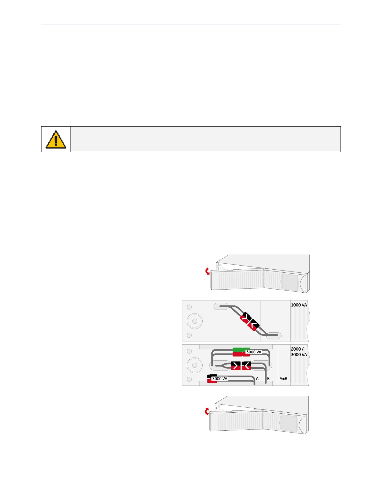
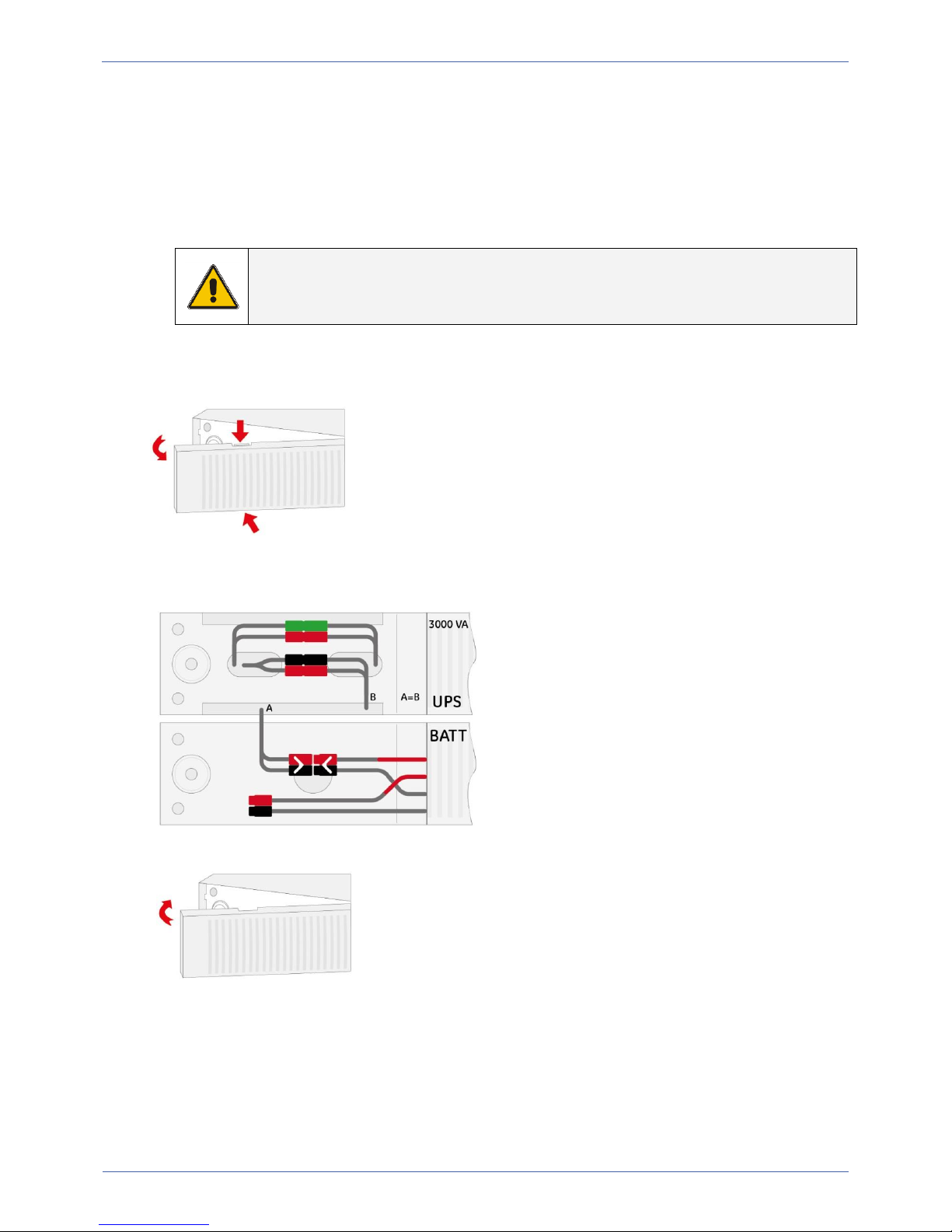
3.1.2 Battery replacement procedure...........................................................................................................................................14
3.2 RECYCLING THE UPS AT THE END OF SERVICE LIFE..........................................................................................................................15
4TROUBLESHOOTING ..................................................................................................................................................................15
5SPECIFICATIONS .........................................................................................................................................................................16

GE
modifications reserved Page 4/16
GE_UPS_OPM_VCO_XXX_1K0_3K0_XGB_V017 User manual - VCO Series UPS 1000-3000VA V017 - GB
1IMPORTANT SAFETY INSTRUCTIONS
1.1 SAVE THESE INSTRUCTIONS
This manual contains important instructions that should be followed during installation and maintenance of the UPS. It
also gives all necessary information about the correct use of the UPS.
Before attempting to install and start up the UPS, carefully read this manual. Keep this manual next to the unit for future
references.
Full understanding of and compliance with the safety instructions and warnings contained in
this manual are the
ONLY CONDITIONS
to avoid any dangerous situation during installation, operation and maintenance work, and to
preserve the maximum reliability of the UPS system
GE refuses any responsibility in case of non-observance, unauthorized alterations or improper use of the delivered UPS.
The instructions in this manual are for UPS models VCO1000, VCO2000 and VCO3000. You can find the model name at
the rear panel of your UPS.
While every care has been taken to ensure the completeness and accuracy of this manual, GE accepts no responsibility
or liability for any loss or damage resulting from the use of the information contained in this document.
1.2 SAFETY RULES
CAUTION! RISK OF ELECTRIC SHOCK
The UPS contains batteries. The appliance outlets may be electrically live, even when the UPS is
disconnected from the mains.
The UPS contains potentially hazardous voltages. Do not open the unit, there are no user serviceable
parts inside.
All maintenance and service work should be performed by qualified service personnel.
Make sure that voltage and frequency of your mains supply match the input specifications of the UPS.
The UPS is intended to be used in normal domestic and office situations.
The branch circuit supply has to be protected with a 16 A building fuse.
The UPS must be powered from a single phase grounded wall outlet. This wall outlet must be easily accessible and
close to the UPS. Do not use extension cords.
Place cables in such a way that no one can step on or trip over them.
Avoid locations that are excessively humid, near water, near heat sources or in direct sunlight.
The ambient temperature should not exceed 40C. Optimal battery lifetime is obtained if the ambient temperature
does not exceed 30C.
It is important that ventilation air can move freely around and through the unit. Do not block the air vents.
The UPS output can be used only for electronic loads such as computers and telecommunications equipment. Life
support or critical medical equipment should not be connected. Do not plug household appliances such as electric
heaters, toasters and vacuum cleaners into the UPS.
The sum of the leakage currents of the UPS and the connected loads should not exceed 3.5mA.
Always disconnect the input power cord from the wall outlet before replacing the battery.
When replacing the batteries, use only the same type and size battery
Never dispose of batteries in a fire: they may explode.
Never disassemble or reassemble batteries; their contents (electrolyte) may be extremely toxic.
Never short the battery terminals. Shorting may cause the battery to burn. When working with batteries remove
watches, rings or other metal objects and only use insulated tools.
Proper disposal of batteries is required: refer to your local codes for disposal requirements.

GE
modifications reserved Page 5/16
GE_UPS_OPM_VCO_XXX_1K0_3K0_XGB_V017 User manual - VCO Series UPS 1000-3000VA V017 - GB
1.3 WARRANTY
GE, operating through its authorized agents, warrants that the standard products will be free of defects in materials and
workmanship for a period as per contract specifications.
NOTE
This warranty does not cover failures of the product which result from incorrect installation, misuse,
alterations by persons other than authorized agents, or abnormal operating conditions.
1.4 STORAGE
Store the UPS in a dry location with the batteries in a fully charged state. Storage temperature must be within
-20C and +60C. If the unit is stored for a period exceeding 3 months, optimal battery lifetime is obtained if the
storage temperature does not exceed 25°C.
If the unit is stored for an extended period of time, the batteries must be recharged every 2 months. Connect the unit
to a wall outlet and recharge the batteries for 24 hours.
CAUTION
In case of storage, pay attention to:
2INSTALLATION
2.1 INTRODUCTION
The GE (General Electric) VCO Series UPS, a truly on-line double conversion uninterruptible power supply, has been
designed to protect your sensitive electronic equipment such as computers and telecommunications equipment from all
forms of power interference, including complete power failures.
When the mains supply is present the UPS keeps the battery in a fully charged state and supplies a completely new and
clean AC power to the connected equipment. In the event of a mains power failure (i.e. absent or outside tolerance) the
system uses the energy reserve stored in the battery to continue to produce AC power, ensuring unbroken output. No
interruption or alteration will ever be noticed in the output power.
The UPS is equipped with an automatic bypass switch. This switch automatically transfers the load to the mains if the
UPS is unable to deliver the demanded output power due to overload or over temperature. The UPS will switch back to
normal operation when the overload has been removed or the temperature has dropped below alarm level.

GE
modifications reserved Page 6/16
GE_UPS_OPM_VCO_XXX_1K0_3K0_XGB_V017 User manual - VCO Series UPS 1000-3000VA V017 - GB
2.2 UNPACKING
The UPS shipping box contains:
a VCO Series UPS
USB cable (type B)
IEC female-male power cord (C13 <-> C14)
Mounting parts for tower and rack use
RJ11 cable
CD ROM with UPS monitoring software (see 2.5)
and its manual
this manual
Inspect the UPS for damage after unpacking. If any damage is present please immediately notify the carrier and place of
purchase.
WARNING! In case of recognizable damage:
DO NOT connect any voltage to the unit
DO NOT put the unit into operation.
Condensation may occur if the UPS system is moved directly from a cold to a warm environment. The UPS system must
be absolutely dry before being installed. Please allow an acclimatization time of at least two hours prior to installation.
Save the original packing material. No liability can be accepted for any transport damage when the equipment is shipped
in non-original packaging.
2.3 INSTALLATION
2.3.1 PREPARATIONS
1. Connect the batteries.
For safety reasons the batteries are not connected during transportation. To reconnect the batteries:
1.a. Open and remove the left part of the front panel,
the “battery door”
1.b. Connect the battery wires
red <-> red, black <-> black
1.c. Re-install and close the battery door.
Fig. 2.3.1.a: connecting the battery

GE
modifications reserved Page 7/16
GE_UPS_OPM_VCO_XXX_1K0_3K0_XGB_V017 User manual - VCO Series UPS 1000-3000VA V017 - GB
2. The UPS can be used as stand alone tower format by using the two supporting stands or can be mounted in a 19
inch rack using the two mounting brackets.
2.a. Vertical installation: Tower
Assemble the two supporting stands at the bottom side of the UPS cabinet.
2.b. Horizontal installation: Rack mount
Install the two mounting brackets at the sides of the UPS cabinet.
Install the UPS into a 19 inch rack. The UPS cabinet must be supported by mounting rails, do not mount it by
using the mounting brackets only. Fix the mounting brackets on the 19 inch enclosure with screws.
CAUTION
Please consider the weight of the UPS prior to installation to ensure the rack is capable of
supporting the weight. We recommend that the UPS is placed in its lower half. Fit the unit into
the rack cabinet with the help of a second person.
3. 3000VA model only: a battery extension pack can be connected to the UPS.
Remove the battery door (2, fig. 2.3.2) and create an opening for the battery cable by cutting/breaking off the piece
indicated in figure 2.3.1.b-1.
Connect the DC connector of the battery pack to the DC connector of the UPS. Using the DC socket of the battery
pack you can install a second, third, etc. pack. As the battery pack is equipped with an integrated battery charger it
must be connected to an AC wall outlet.
Reinstall the battery door.
To adapt the runtime prediction, re-program the new total battery capacity with the UPS monitoring software.
Please note that:
during re-programming the UPS must be in standby mode (see 2.4.2.3)
only the standard values can be set, i.e. 9/23/37/51Ah.
Fig. 2.3.1.b-2: connecting battery extension
pack to 3000VA model
Fig. 2.3.1.b-1
Fig. 2.3.1.b-3

GE
modifications reserved Page 8/16
GE_UPS_OPM_VCO_XXX_1K0_3K0_XGB_V017 User manual - VCO Series UPS 1000-3000VA V017 - GB
2.3.2 FRONT AND REAR PANEL
1. Operating panel
See section 2.4.1.
2. Battery door
Covering the DC connector
3. Input socket
AC mains supply to the UPS.
4. Input circuit breaker
Protects the UPS from damage caused
by high input currents.
5. Appliance outlets
To connect the loads to the UPS. Group
5-1 is always on, group 5-2 can be
switched on or off. By switching off
group 2 during a power failure you can
increase the remaining runtime for the
essential equipment connected to
group 1. See 2.4.5.
6. Output circuit breakers (VCO3000 only)
In case of a severe overload the output breaker may trip. The button will come out, the UPS is disconnected from
the mains and output power is lost. In this situation reduce the load connected to the outlets of the UPS.
Subsequently reset the circuit breaker by pushing the button back in.
7. Fan(s)
8. Phone/FAX/Modem protection
The RJ11 jacks can provide protection against surges and spikes on your phone line.
9. USB port*
10. RS232 port*
11. Slot for optional communication card*
12. EPO port - Emergency Power Off interface
See 2.3.5 for more information.
* See 2.5 for more information.
Fig. 2.3.2: front and rear panels

GE
modifications reserved Page 9/16
GE_UPS_OPM_VCO_XXX_1K0_3K0_XGB_V017 User manual - VCO Series UPS 1000-3000VA V017 - GB
2.3.3 CONNECTING POWER AND LOAD
1. To connect a VCO1000 or VCO2000 UPS to the mains you can use the original MAINS <-> IEC C13 power cable of
the computer that will be protected by the UPS. For a VCO3000 you will need a MAINS <-> IEC C19 power cable.
These cables are not part of delivery.
2. Connect the power cord (see step 1) to the male input socket (3) at the rear of the UPS and to a working, grounded
AC wall socket outlet. The UPS is in Standby mode now, and though the unit is still switched off it will now start
recharging the battery. On the display the symbols “Charging” and “AC Normal” are lit.
3. For best results, allow the UPS to recharge the batteries during a period of approx. 8 hours. It is acceptable to use
the UPS without first charging the battery, but the runtime may be reduced.
4. Add up the power consumption (in VA) of the appliances that will be protected by the UPS (‘the load’) and make
sure that the resulting value does not exceed the VA output rating of the UPS. This way you ensure that the UPS is
able to supply the required output and prevent that an overload situation will happen.
5. Plug the load (e.g. computer, monitor, critical data storage device, etc.) into the appliance outlets (5-1 and 5-2) of
the unit. Spread the loads over the appliance outlets as equally as possible. If you use a distribution box to connect
more than one appliance per outlet, please note that
the maximum AC-current rating of each appliance
outlet is 7A for VCO1000 and 10A for VCO2000 &
VCO3000. Outlets 5-1 are always on, outlets 5-2 can
be switched off.
CAUTION!
Do NOT plug LASER PRINTERS or 3-D PRINTERS into any of the appliance outlets. These devices have a
much higher power demand than typical peripherals.
NOTE
The UPS output sockets can be live as soon as the UPS is connected to the main power supply, even if
the UPS has not been switched on via the front panel.
2.3.4 CONNECTING INTERFACE DEVICES
The UPS is equipped with two interface ports: a USB port and an RS232 port, allowing advanced communication between
the UPS and a computer (network). Refer to section 2.5 for more detailed information.
2.3.5 CONNECTING EPO - EMERGENCY POWER OFF
EPO - Emergency Power Off may be created by replacing the link with a switch with the characteristics of a ‘power off’
button. Under normal conditions the switch has to be closed, when it opens the UPS will transfer to stand-by mode and
output power is lost.
It is not possible to restart the unit while the EPO switch is open. After closing the EPO switch press 'ON/mute' button for 2
seconds in order to restart the unit.

GE
modifications reserved Page 10/16
GE_UPS_OPM_VCO_XXX_1K0_3K0_XGB_V017 User manual - VCO Series UPS 1000-3000VA V017 - GB
2.4 OPERATION
2.4.1 OPERATING PANEL
1. Button “ON/Mute”
Turns the UPS ON and mutes the alarm during battery operation, see 2.4.2.
NOTE: The alarm cannot be muted if generated during abnormal operating conditions.
Starts a self-test: see 2.4.4.
2. Button “SELECT”
Switch LCD message: Press this button to switch between voltage (input/output), frequency (input/output), current
(output) and power (output).
Setting mode: see 2.4.5.
3. Button “OFF/Enter”
Turns off the UPS: See 2.4.2.
Confirm “Select”: press the button to confirm the selection made with button “SELECT”. See 2.4.5.
4. Bar “Load capacity” –shows the actual load as a % of the nominal load.
5. Bar “Battery capacity” –shows the battery charge level in 20% steps. When the UPS operates in Battery mode
this bar counts down, indicating that the battery is being discharged.
6. ECO: the ECO function is enabled. See 2.4.3.5.
MUTE: the audible alarm is muted. See 2.4.2.2.
1-ON: the appliance outlet group 1 is on. This group is always on.
2-ON: the appliance outlet group 2 is on. This group can be switched off. See 2.3.2 and 2.4.5.
XXX: three digits show the actual value of the parameter selected
IN/OUT: parameter shown refers to input or output respectively
MIN: minutes (REMAINING TIME during battery operation)
V/HZ/A/KW: parameters of voltage (input/output), frequency (input/output), current (output) and power (output).
7. AC NORMAL –the incoming mains power is present and within voltage and frequency tolerances.
8. CHARGING –the batteries are being charged.
9. BATT. MODE –the UPS operates in battery mode: it uses the energy stored in the batteries.
The “Battery capacity” bar shows the remaining battery capacity.
10. BYPASS - the UPS operates in bypass mode. See 2.4.3.4.
11. OVERLOAD –the load connected to the UPS exceeds the nominal rating of the unit.
12. ALARM –indicates an abnormal situation.
Fig. 2.4.1: operating panel

GE
modifications reserved Page 11/16
GE_UPS_OPM_VCO_XXX_1K0_3K0_XGB_V017 User manual - VCO Series UPS 1000-3000VA V017 - GB
Display and buzzer alarm list
# Symbol
Buzzer alarm
UPS operating status
7 + 8
OFF
Standby mode: UPS switched off, input voltage present, battery charging
7
OFF
AC mode –normal operation
9
1 beep / 4 seconds
DC (battery) mode - battery capacity >= 40%
7+11+12
2 beeps / second
AC mode –output overload (102-129%), after 15 secs transfer to bypass
9+11+12
2 beeps / second
DC mode –output overload (102-129%) after 15 secs shutdown
9+12
1 beep / second
DC mode –battery capacity <= 20%
7+11+12
2 beeps / second
AC mode –output overload (130-149%), after 2 secs transfer to bypass
9+11+12
2 beeps / second
DC mode –output overload (130-149%), after 2 secs shutdown
7+11+12
2 beeps / second
AC mode –output overload (>150%), immediate transfer to bypass
9+11+12
2 beeps / second
DC mode –output overload (>150%), immediate shutdown
12
continuous
abnormal operating condition:
output short circuit; Inverter over/under voltage; Over temperature; Charger
over voltage; Charger fault; Bus over/under voltage
2.4.2 USE: START-UP AND SWITCH OFF
2.4.2.1 Start-up the UPS, mains available
To switch on the UPS press and hold the “ON/Mute”button (1) for at least 2 seconds. On the display the symbols “AC
NORMAL” (7) and “CHARGING” (8) are lit. NOTE: When you turn on the UPS it will perform a self-test.
2.4.2.2 Start-up the UPS, mains not available
If you switch on the UPS if mains power is not available, the UPS is started up in battery mode: it discharges the batteries.
The symbol “BATT MODE” (9) lights and an alarm sounds. To mute this alarm press and hold the “ON/Mute”button for at
least 4 seconds to toggle between alarm on/off. This switch does not mute the alarm in case of low battery voltage or
abnormal operating conditions.
2.4.2.3 Switch off the UPS
Press and hold the OFF/Enter button (3) for at least 2 seconds. If the UPS operates in AC mode it will switch to standby, if
the unit operates in battery mode it will switch off.
2.4.3 USE: OPERATING MODES
2.4.3.1.Standby Mode
Mains supply is connected, battery is charging but UPS is not switched on yet. On the display the symbols “AC NORMAL”
(7) and “CHARGING” (8) are lit.
2.4.3.2 AC Mode (normal operation)
On the display the symbols “AC NORMAL” (7) and “CHARGING” (8) are lit.
The mains voltage is present, the UPS supplies the connected equipment and keeps the battery in a fully charged state.
The load is isolated from surges and electrical noise brought by the mains wiring.
2.4.3.3 DC Mode (Battery Mode)
On the display the symbol “BATT. MODE” (9) is lit. The mains power fails and the UPS uses the energy stored in the batteries
until either they are depleted or mains power returns. The “Battery capacity” bar (5) shows the remaining battery capacity
and the buzzer sounds. To mute this alarm press and hold the “ON/Mute” button for at least 4 seconds to toggle between
alarm on/off.

GE
modifications reserved Page 12/16
GE_UPS_OPM_VCO_XXX_1K0_3K0_XGB_V017 User manual - VCO Series UPS 1000-3000VA V017 - GB
2.4.3.4 Bypass Mode
If the UPS is unable to deliver the demanded output power (most probably due to overload or over temperature) it
automatically switches to bypass mode: the incoming mains power is channeled directly to the load. The UPS will switch
back to normal operation when the overload has been removed or the temperature has dropped below alarm level.
If a power failure occurs during this automatic bypass mode, the UPS will most probably not be able to deliver the
demanded output power and output power is lost.
The load can be switched to bypass manually: press the two buttons “ON/Mute”(1) and “SELECT”(2) simultaneously for 4
seconds. The unit switches to bypass mode and symbol “BYPASS” (10) is lit. In this state the UPS operates on bypass
regardless of the input. Press the two buttons “ON/Mute”and “SELECT”simultaneously for 4 seconds again to switch the
UPS back to normal operation. If a power failure occurs during manual bypass mode output power is lost.
2.4.3.5 ECO Mode
For energy saving purposes the unit can be switched into ECO mode. See 2.4.5 for instructions.
During ECO Mode, the symbol “ECO” will be lit. The UPS operates on bypass (without alarms) as long as input voltage and
frequency are within limits. If a power failure occurs during ECO Mode the UPS switches to battery operation. If the mains
returns the unit will switch back to ECO Mode.
2.4.4 USE: SELF-TEST FUNCTION
To start a self-test: when the UPS is in AC mode or ECO mode press the “ON/Mute” button for 4 seconds.
The self-testing function includes load detection, battery capacity and abnormal state.
2.4.5 USE: OPERATING PARAMETER SETTING
Enter the configuration mode
When the UPS is in Standby or operates in Bypass mode, press and hold the “SELECT” button (2) for 4 seconds.
When the UPS enters the configuration mode, status indicator symbols will light that represent the actual parameter
being programmed.
Select the parameter by pressing the “ON/MUTE“button once.
Select the setting by pressing the “SELECT“button once.
Confirm the setting by pressing the “OFF/Enter” button once.
Parameters and settings
1. Output frequency 50Hz
60Hz
Auto Select (default setting)
2. Output voltage 208V
220V
230V (default setting)
240V
3. ECO Mode Disabled (default setting)
Enabled
4. Outlets group 2 On (default setting)
Off
Exit the configuration mode
Press and hold the “OFF/Enter” button (3) for 2 seconds. The UPS will return to normal operation.

GE
modifications reserved Page 13/16
GE_UPS_OPM_VCO_XXX_1K0_3K0_XGB_V017 User manual - VCO Series UPS 1000-3000VA V017 - GB
2.5 COMMUNICATION
You can communicate with the UPS via either SNMP, USB or RS232. Simultaneous communication via more than one
interface is not possible. The priority is SNMP > USB > RS232. The hardware will detect the connection port to select the
communication interface.
2.5.1 USB AND RS232 COMMUNICATION PORTS
The USB and RS232 ports are plug-in interface ports that enable advanced communication between the UPS and the
computer (UPS software required). The interface ports are operative as soon as the mains power cord is plugged into a
live wall outlet, even if the UPS is switched off.
For more information please refer to the user manual that comes with the interface software. We strongly recommend to
use only original GE software products in combination with the interface ports.
Pin # Function
1 Battery low
2 RS-232 transmission pin (TXD).
3 RS-232 receive pin (RXD). Remote Shutdown
4 Not used
5 Common & Signal Ground
6 Bypass Active
7 Not used
8 Mains failure
9 General alarm
2.5.2 COMMUNICATION CARD (OPTION)
The SNMP card makes the UPS ‘SNMP manageable’: it allows the data interface to be connected directly to an Ethernet
network. For more information please refer to the user manual that comes with the interface card.

GE
modifications reserved Page 14/16
GE_UPS_OPM_VCO_XXX_1K0_3K0_XGB_V017 User manual - VCO Series UPS 1000-3000VA V017 - GB
3MAINTENANCE
3.1 BATTERY REPLACEMENT
3.1.1 GENERAL GUIDELINES
When replacing the batteries, use only the same type and size battery.
Never short the battery terminals. Shorting may cause the battery to burn. When working with batteries remove
watches, rings or other metal objects and only use insulated tools.
Avoid charging in a sealed container.
Never dispose of batteries in a fire: they may explode.
Never disassemble or reassemble batteries; their contents (electrolyte) may be extremely toxic. If exposed to
electrolyte, wash immediately with plenty of water, if eye contact occurs flush with water and contact a physician.
3.1.2 BATTERY REPLACEMENT PROCEDURE
(Qualified service personnel only)
1. Turn off the equipment that is connected to the output sockets of the UPS.
2. Turn off the UPS.
3. Unplug the UPS power cord from the AC wall outlet.
4. Unplug the equipment from the output sockets of the UPS.
5. Remove the front panel (fig. 5).
6. Disconnect the battery wires (fig. 6).
7. Loosen the screws that hold the cover of the battery compartment.
8. 8.a - VCO1000/2000/3000: Remove the battery box (fig. 8.a and 8.a.1).
8.b - VCO3000 only: Remove the additional battery box (fig 8.b).
9. Remove the top cover of the battery box, replace the batteries inside
(fig. 9).
10. Reinstall the top cover of the battery box, reverse of step 9.
11. 11.a –VCO3000 only: Insert the new additional battery box, reverse of
step 8b.
11.b –VCO1000/2000/3000: Insert the new battery box, reverse of
step 8a.
12. Reinstall the cover of the battery compartment and fasten the screws,
reverse of step 7.
13. Reconnect the battery wires, reverse of step 6.
14. Reinstall the front panel, reverse of step 5.
Fig. 5
Fig. 6
Fig. 8.a
Fig. 8.a.1
Fig. 8.b
Fig. 9

GE
modifications reserved Page 15/16
GE_UPS_OPM_VCO_XXX_1K0_3K0_XGB_V017 User manual - VCO Series UPS 1000-3000VA V017 - GB
3.2 RECYCLING THE UPS AT THE END OF SERVICE LIFE
The batteries contain lead, which is a harmful substance for the environment.
Proper disposal or recycling of the batteries is required. Refer to your local codes for
disposal requirements!
GE, in compliance with environment protection recommends that the UPS equipment, at the end of its
service life, must be recycled conforming to the local applicable regulations.
4TROUBLESHOOTING
Whenever a malfunction occurs, first check external factors (e.g. connections, temperature, humidity or load) to
determine whether the problem is caused by the unit itself or by its environment. Subsequently check the thermal circuit
breaker: it may be tripped. If so: reset it and be sure that the UPS is not overloaded.
The following chart is a simple troubleshooting checklist only. If the suggested solution does not succeed, or if the
information is insufficient to solve the problem, please contact your dealer or consult www.gecriticalpower.com.
Make sure you have the following information available when you call for service: Model number / serial number, date of
purchase and full description of the problem.
PROBLEM
POSSIBLE CAUSE
SOLUTION
UPS will not switch on
and symbol “AC normal”
is not lit
UPS line cord not connected and/or
UPS is not switched on
Press and hold the “ON/Mute” button for at least 2
seconds
Battery voltage is too low
Recharge the battery for at least 4 hours
UPS always in Battery
mode
Power cord not connected
Connect power cord
Input circuit breaker tripped
Reduce the load, reset the circuit breaker
Dead wall socket outlet, or mains
voltage out of limits
Contact qualified electrician
UPS does not provide the
expected runtime
The battery is not fully charged or
aging battery
Remove non-critical load, charge the battery for at
least 6 hours and re-test the runtime. If the
situation persists replace the battery.
UPS slightly overloaded
Reduce the load
During mains failure the
UPS automatically turns
off
The battery is not fully charged or
aging battery
Remove non-critical load, charge the battery for at
least 6 hours and re-test the runtime. If situation
persists, have the battery replaced.
UPS overload
Remove non-critical load, re-start the UPS and
charge the battery for at least 6 hours
During mains failure
buzzer sounds 1x/4sec
and symbol “Overload” is
lit
UPS is overloaded during DC mode,
unit will (or already has) shut down
within max. 15 seconds
Reduce the load (and re-start the UPS)
Mains is present, buzzer
sounds 2x/sec, symbol
“Overload” is lit
UPS is overloaded during AC mode,
UPS will switch (or already has
switched) to Bypass mode
Reduce the load
PB

GE
modifications reserved Page 16/16
GE_UPS_OPM_VCO_XXX_1K0_3K0_XGB_V017 User manual - VCO Series UPS 1000-3000VA V017 - GB
5SPECIFICATIONS
Model
:
VCO1000
VCO2000
VCO3000
Rating VA/W
:
1000/800
2000/1600
3000/2400
Input
AC input voltage
:
208 / 220 / 230 / 240Vac
AC input voltage range
:
120 ~ 280Vac
Frequency
:
50 / 60 Hz (auto-sensing)
Power factor
:
> 0.95 at full load
Output
AC output voltage
:
208 / 220 / 230 / 240Vac (selectable)
AC output voltage tolerance
:
±3% at linear load
Output frequency
:
50 / 60 Hz (selectable)
Output frequency stability
:
nominal ±0.3Hz unless synchronized to the mains
Output waveform
:
sine wave
Power factor
:
0.8 lagging
Harmonic distortion
:
3% at linear load
Overload capability
:
102~129% for 15 sec./ 130~149% for 2 sec./ >150% immediately:
- if in AC mode: transfer to bypass
- if in DC mode: UPS shutdown
Battery
Battery type
:
12V, sealed lead acid, maintenance free
Nominal voltage (Vdc)
:
24
48
72
Number x capacity of battery
:
2x9Ah
4x9Ah
6x9Ah
Battery recharge time
:
< 8 hours for 90% capacity (standard battery)
Runtime in minutes at typical load (60%)
:
7
8
8
General
Weight (kg)
:
16
32
38
Dimensions (hxwxd)
:
88x440x405mm
88x440x620mm
88x440x620mm
Enclosure / protection
:
steel-plastic / IP20
Communication
Communication ports
:
USB and RS232
Environment
Safety
:
IEC/EN 62040-1
Electromagnetic compatibility
:
IEC/EN 62040-2
Ambient temperature
:
0°C ~ 40°C
Sound at 1 meter
:
< 55 dB(A), load and temperature dependent
Maximum relative humidity
:
95% (non-condensing)
Filtering
Power line surge suppression
:
768 / 476 Joules; max. peak 4500A; clamping rate 180/330Vrms;
response time normal mode 0ns, common mode <1ns
EMI/RFI noise filter (at 1MHz)
:
up to 60dB
Internet / phone / fax protection
:
RJ-11 (One pair), 2C; 114 joules; clamping rate 330V
This document shall not be copied nor reproduced without the permission of GE.
Due to technical improvements, some of the information contained in this manual may be changed without notice.
© General Electric Consumer & Industrial SA. All rights reserved; reproduction without permission prohibited. The content of this
manual may be subject to change without prior notice; no liability can be accepted for any error or omission. The illustrations and
plans describing the equipment are intended as general reference only and are not necessarily complete in every detail.
This manual suits for next models
2
Table of contents
Other GE Consumer & Industrial UPS manuals
Popular UPS manuals by other brands

Rockwell Automation
Rockwell Automation 1606-XLS240-UPSC instruction manual

lapara
lapara LA-ITR-800-LCD user manual

Toshiba
Toshiba T1000 Series Installation and operation manual

Emerson
Emerson Liebert NXL installation manual

INFOSEC
INFOSEC X2 LCD Touch FR/SCHUKO 500 user guide

Mecer
Mecer ME-650-VU user manual