GE Consumer & Industrial TLE Series 160 User manual

Critical Power
Installation Guide
Uninterruptible Power Supply
GE Consumer & Industrial SA
General Electric Company
CH – 6595 Riazzino (Locarno)
Switzerland
T +41 (0)91 / 850 51 51
F +41 (0)91 / 850 52 52
www.gecriticalpower.com
imagination at work
TLES_UL_160-500_S2b_UPS_GE_01
TLE Series 160/200/225/ 250
TLE Series 300/350/400/500

Critical Power
Modifications reserved
Page 2/60
GE_UPS_ISG_TLE_SUL_M16_M50_2bU_V010.docx
Installation Guide TLE Series 160 - 500 UL S2B
Model:
TLE Series 160 - 200 - 225 – 250 – 300 – 400 - 500 UL S2B
Issued by:
Product Document Department – Riazzino - CH
Approved by:
R & D Department – Riazzino - CH
Date of issue:
04/23/2018
File name:
GE_UPS_ISG_TLE_SUL_M16_M50_2bU_V010
Revision:
1.0
Identification No.:
8600180579P
Up-dating
Revision Concern Date
COPYRIGHT © 2018 by GE Consumer & Industrial SA
All rights reserved.
The information contained in this publication is intended solely for the purposes indicated.
The present publication and any other documentation supplied with the UPS system is not to be
reproduced, either in part or in its entirety, without the prior written consent of GE.
The illustrations and plans describing the equipment are intended as general reference only and are not
necessarily complete in every detail.
The content of this publication may be subject to modification without prior notice.

Critical Power
Modifications reserved
Page 3/60
GE_UPS_ISG_TLE_SUL_M16_M50_2bU_V010.docx
Installation Guide TLE Series 160 - 500 UL S2B
Dear Customer,
We thank you for selecting our products and are
pleased to count you amongst our very valued
customers at GE.
We trust that the use of the TLE Series 160 - 500
Uninterruptible Power Supply S
ystem, developed and
produced to the highest standards of quality
, will give
you complete satisfaction.
Please read carefully the Installation Guide
, which
contains all the necessary information and describes all
you need to know about the installation of the UPS.
Thank you for choosing GE !
START-UP AND COMMISSIONING
A GE GLOBAL SERVICES FIELD ENGINEER must perform start-
up and
commissioning of the UPS.
Please Contact GE GLOBAL SERVICES at least two weeks prior to schedule
start-up and commissioning at 1-800-637-1738, or by E-
mail at
pqservice@ge.com .
Distributed in the USA by
Your Service Center
g
GE Consumer & Industrial SA
General Electric Company
CH – 6595 Riazzino (Locarno)
Switzerland
www.gecriticalpower.com
g
GE Energy Connections
Critical Power
3100 Technology – Suite 200
Plano, TX 75074
T: +1 800-637-1738
www.geindustrial.com/products/
critical-power
g
GE Energy Connections
Critical Power
601 Shiloh Road
Plano, TX 75074
24/7 T: +1 800-637-1738
24/7 F: +1 866-765-3595
E: pqservice@ge.com

Critical Power
Modifications reserved
Page 4/60
GE_UPS_ISG_TLE_SUL_M16_M50_2bU_V010.docx
Installation Guide TLE Series 160 - 500 UL S2B
Preface
Congratulations on your choice of a TLE Series Uninterruptible Power Supply (UPS).
It will help eliminate load disturbances due to unexpected power problem
.
This
Installation Guide
describes how to prepare the installation site, and it provides
weight and
dimensions and procedures for moving, installing and connecting the UPS.
Please refer to the
accompanying User Manual
, which describes the function of the UPS
module, the purpose and location of the switches, the meaning of the system events
related to the front panel indication, and provides procedures for starting and stopping
the equipment.
While every care has been taken to ensure the completeness and accuracy of this manual,
GE
assumes no responsibility or liability for any losses or damages result
ing from the use
of the information contained in this document.
WARNING!
TLE Series 160 - 500 is a Category C3 UPS Product (according to IEC 62040-2).
This is a product for commercial and industrial application in the second environment −
installation restrictions or additional measures may be needed to prevent disturbances.
We recommend that this manual be kept next to the UPS for future references.
If any problems are encountered with the procedures contained in this manual, please
contact your
GE Service Center before you proceed.
This document shall not be copied or reproduced without the permission of
GE.
Some of the information contained in this manual may be changed without notice to
reflect technical improvements.
Safety instructions
Read
the safety instructions contained on the following pages carefully before the
installation of the UPS, options and battery system.
Pay attention to the rectangular boxes included in the text:
They contain important information and warning concerning electrical connections and
personnel safety
.
Parallel System version secured with RPA
When included in the text, this symbol refers to operation needed
only for RPA Parallel System.

Critical Power
Modifications reserved
Page 5/60
GE_UPS_ISG_TLE_SUL_M16_M50_2bU_V010.docx
Installation Guide TLE Series 160 - 500 UL S2B
Table of content Page
1IMPORTANT SAFETY INSTRUCTIONS .............................................................................................................................6
2LAYOUT...............................................................................................................................................................................9
2.1 LAYOUT TLE SERIES 160 - 220 - 225 - 250....................................................................................................................................................... 9
2.2 LAYOUT TLE SERIES 300 - 400 - 500................................................................................................................................................................ 11
3ENVIRONMENT................................................................................................................................................................13
3.1 RECYCLING INSTRUCTIONS.................................................................................................................................................................................. 13
4INSTALLATION.................................................................................................................................................................14
4.1 TRANSPORT................................................................................................................................................................................................................. 14
4.1.1 Dimensions and weights TLE Series 160 - 500 ........................................................................................................................................................... 15
4.2 DELIVERY...................................................................................................................................................................................................................... 16
4.3 STORAGE...................................................................................................................................................................................................................... 16
4.3.1 Storage of the UPS.................................................................................................................................................................................................................... 16
4.3.2 Storage of Battery..................................................................................................................................................................................................................... 16
4.4 PLACE OF INSTALLATION...................................................................................................................................................................................... 17
4.4.1 UPS location ................................................................................................................................................................................................................................. 17
4.4.2 Battery location.......................................................................................................................................................................................................................... 20
4.5 VENTILATION AND COOLING............................................................................................................................................................................... 21
4.6 UNPACKING................................................................................................................................................................................................................ 22
4.7 ELECTRICAL WIRING ............................................................................................................................................................................................... 24
4.7.1 Utility input connection........................................................................................................................................................................................................... 24
4.7.2 Input/output over current protection and wire sizing............................................................................................................................................. 25
4.7.3 Data for Input/output and battery over current protection and wire sizing ............................................................................................... 26
4.7.4 Installation requirements....................................................................................................................................................................................................... 29
4.8 WIRING CONNECTION............................................................................................................................................................................................ 32
4.8.1 TLE Series 160 - 200 - 225 - 250 Power connection with Common Input Utility..................................................................................... 35
4.8.2 TLE Series 160 - 200 - 225 - 250 Power connection with Dual Input Utility............................................................................................... 37
4.8.3 TLE Series 300 - 400 - 500 Power connection with Common Input Utility ................................................................................................. 40
4.8.4 TLE Series 300 - 400 - 500 Power connection with Dual Input Utility........................................................................................................... 42
4.8.5 Use of TLE Series 160 - 500 in eBoost™ Operation Mode..................................................................................................................................... 45
4.8.6 Use of TLE Series 160 - 500 as frequency converter ............................................................................................................................................... 46
4.9 RPA PARALLEL SYSTEM CONNECTION ............................................................................................................................................................ 47
4.9.1 Power wiring of parallel units.............................................................................................................................................................................................. 47
4.9.2 Parallel control bus connection.......................................................................................................................................................................................... 48
4.9.3 Control bus cable location .................................................................................................................................................................................................... 50
4.10 “EPO - EMERGENCY POWER OFF” COMMAND CONNECTION ............................................................................................................... 52
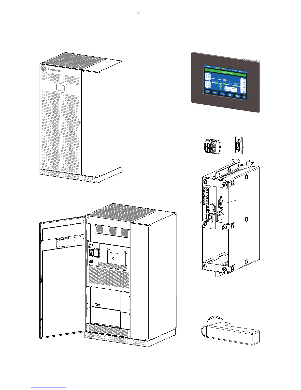
5CUSTOMER INTERFACE..................................................................................................................................................54
5.1 SERIAL PORT J35µP - RS232 (SUB D, FEMALE 9 PIN)................................................................................................................................. 55
5.2 CUSTOMER INTERFACE BOARD.......................................................................................................................................................................... 56
5.2.1 Connector J1 – RJ45 8P8C .................................................................................................................................................................................................... 57
5.2.2 X1 terminal block - Output signals on voltage-free contacts ............................................................................................................................. 57
5.2.3 X1 terminal block - Programmable input free contacts......................................................................................................................................... 57
5.2.4 X2 terminal block – “EPO - Emergency Power Off” ................................................................................................................................................... 58
5.2.5 X1 terminal block - Gen Set Signaling (GEN ON)......................................................................................................................................................... 58
5.2.6 X1 terminal block - AUX external Maintenance Bypass......................................................................................................................................... 59
5.2.7 X1 terminal block - eBoost/IEMi control signal........................................................................................................................................................... 59
6NOTES...............................................................................................................................................................................60
6.1 NOTES FORM.............................................................................................................................................................................................................. 60

Critical Power
Modifications reserved
Page 6/60
GE_UPS_ISG_TLE_SUL_M16_M50_2bU_V010.docx
Installation Guide TLE Series 160 - 500 UL S2B
1IMPORTANT SAFETY INSTRUCTIONS
SAVE THESE INSTRUCTIONS
This manual contains important instructions for models TLE Series 160 - 500 that should be followed
during installation and maintenance of the UPS and battery.
GENERAL
- Move the UPS in an upright position in its original package to the final destination room.
To lift the cabinets, use a forklift or lifting belts with spreader bars.
- Check for sufficient floor and elevator loading capacity.
- Check the integrity of the UPS equipment carefully.
If you notice visible damage, do not install or start the UPS.
Contact the nearest GE Service Center immediately.
- WARNING! RISK OF ELECTRICAL SHOCK:
Do not remove covers, there are no user serviceable parts inside.
- After switching off takes 5 minutes for the DC capacitors to discharge because a lethally high voltage
remains at the terminals of the electrolytic capacitors.
- UPS’s and battery system require a 12 months periodic maintenance to operate reliably and safely.
This should be performed by qualified service personnel. The UPS contains its own energy source (battery).
- The field-wiring outlets may be electrically live, even when the UPS is disconnected from the utility.
- Dangerous voltages may be present during battery operation.
- The battery must be disconnected during maintenance or service work.
- This UPS contains potentially hazardous voltages.
- Be aware that the inverter can restart automatically after the utility voltage is restored.
- End user must follow applicable regional occupational safety codes/regulations during installation,
operation and equipment maintenance. This may require additional field marking or labeling defining
appropriate level of PPE (Personal Protection Equipment) to reduce the risk of Arc-flash related injuries.
Contact our GE Service Center for product specific information.
INSTALLATION
- This UPS must be installed and connected only by trained personnel.
- Verify accurately during Commissioning and Maintenance of the UPS, for the following:
Damaged components, squeezed wires and cables, or not correctly inserted plugs.
- After removing the sidewalls of the UPS, make sure that all earth connections when reassembling, are
correctly reattached.
- This UPS is intended for use in a controlled indoor environment free of conductive contaminants and
protected against animals intrusion.
- WARNING! HIGH EARTH LEAKAGE CURRENT:
Earth connection is essential before connecting to AC input!
- Switching OFF the unit does not isolate the UPS from the utility.
- Do not install the UPS in an excessively humid environment or near water.
- Avoid spilling liquids on or dropping any foreign object into the UPS.
- The unit must be placed in a sufficiently ventilated area; the ambient temperature should not exceed 104°F
(40°C).
- Optimal battery life is obtained if the ambient temperature does not exceed 77°F (25°C).
- It is important that air can move freely around and through the unit. Do not block the air vents.
- Avoid locations in direct sunlight or near heat sources.
STORAGE
-Store the UPS in a dry location; storage temperature must be within -13°F (-25°C) to 131°F (55°C).
-The optimal temperature for Battery storage is 68°F (20°C) to 77°F (25°C) and shall never exceed the range -
4°F (-20°C) to 104°F (40°C).
- If the unit is stored for a period exceeding 3 months, the battery must be recharged periodically (time
depending on storage temperature).
BATTERY
- The battery-voltage is dangerous for person’s safety.
- When replacing the battery, use the same cells number, voltage (V), capacity (Ah).
All the battery used, shall be of the same manufacturer and date of production.
- Proper disposal or recycling of the battery is required.
Refer to your local codes for disposal requirements.
- Never dispose of battery in a fire: they may explode.
- Do not open or mutilate battery: their contents (electrolyte) may be extremely toxic.
If exposed to electrolyte, wash immediately with plenty of water.
- Avoid charging in a sealed container.
- Never short-circuit the batteries.
When working with batteries, remove watches, rings or other metal objects, and only use insulated tools.
- In case of air shipment, the cables +/- going to the battery fuses/terminals shall be disconnected and isolated.

Critical Power
Modifications reserved
Page 7/60
GE_UPS_ISG_TLE_SUL_M16_M50_2bU_V010.docx
Installation Guide TLE Series 160 - 500 UL S2B
Safety instructions when working with battery
EXTERNAL BATTERY MUST BE INSTALLED AND CONNECTED TO THE UPS BY
QUALIFIED SERVICE PERSONNEL.
INSTALLATION PERSONNEL MUST READ THIS ENTIRE SECTION BEFORE HANDLING
THE UPS AND BATTERY.
DANGER!
Full voltage and current are always present at the battery terminals.
The battery used in this system can provide dangerous voltages, extremely high currents and a risk of
electric shock.
If the terminals are shorted together or to ground they may cause severe injury.
You must be extremely careful to avoid electric shock and burns caused by contacting battery terminals
or shorting terminals during battery installation.
Do not touch uninsulated battery terminals.
A qualified service person, who is familiar with battery systems and required precautions, must install and
service the battery.
The installation must conform to national and local codes.
Keep unauthorized personnel away from the battery.
The qualified service person must take these precautions:
1Wear protective clothing, such as rubber gloves and boots and protective eye wear.
Batteries contain caustic acids and toxic materials and can rupture or leak if mistreated.
Remove rings and metal wristwatches or other metal objects and jewellery.
Do not carry metal objects in your pockets where the objects can fall into the battery cabinet.
High energy through conductive materials could cause severe burns.
2Tools must have insulated handles and must be insulated so that they will not short battery
terminals.
Do not allow a tool to short between individual or separate battery terminals or to the cabinet or
rack.
Do not lay tools or metal parts on top of the battery, and do not lay them where they could fall onto
the battery or into the cabinet.
3Disconnect charging source prior to connecting or disconnecting battery terminals.
Install the battery as shown on the drawing provided with the battery.
When connecting cables, never allow a cable to short across a battery’s terminals, the string of
battery, or to the cabinet or rack.
4Align the cables on the battery terminals so that the cable lug will not contact any part of the cabinet
or rack, even if the battery is moved.
Keep the cable away from any sharp metal edges.
5Install the battery cables in such a way that the UPS or battery cabinet doors cannot pinch them.
6Do not connect the battery terminal to Ground.
If any battery terminal is inadvertently grounded, remove the source of the ground.
Contacting any part of a grounded battery can cause a risk of electric shock.
7Determine if battery is inadvertently grounded. If inadvertently grounded, remove source from
ground. Contact with any part of a grounded battery can result in electrical shock.
The likelihood of such shock can be reduced if such grounds are removed during installation and
maintenance.
8To reduce the risk of fire or electric shock, install the battery in a temperature and humidity
controlled indoor area, free of contaminants.
9Battery system chassis ground (earth) must be connected to the UPS chassis ground (earth).
If you use conduits, this ground conductor must be routed in the same conduit as the battery
conductors.
10 Where conductors may be exposed to physical damage, protect the conductors in accordance with
all applicable codes.
11 If you are replacing the battery or repairing battery connections, shut OFF the UPS and remove the
battery fuses.

Critical Power
Modifications reserved
Page 8/60
GE_UPS_ISG_TLE_SUL_M16_M50_2bU_V010.docx
Installation Guide TLE Series 160 - 500 UL S2B
Safety symbols and warnings
Safety warnings
The text of this manual contains some warnings to avoid risk to the persons and to avoid damages to
the UPS system and the supplied critical loads.
The non-observance of the warnings reminding hazardous situations could result in human injury and
equipment damages.
Please pay attention to the meaning of the following warnings and symbols.
Throughout this manual the following symbols are defined:
WARNING, if instruction is not followed injury or serious equipment damage may
occur!
CAUTION, internal parts have dangerous voltage present.
Risk of electric shock!
PE (Earth) – GND (Ground)
PROTECTIVE GROUNDING TERMINAL:
A terminal which must be connected to earth ground prior to making any other
connection to the equipment.
A terminal to which or from which an alternating (sine wave) current or voltage
may be applied or supplied.
A terminal to which or from which a direct current or voltage may be applied or
supplied.
This symbol indicated the word “phase”.
This symbol indicates the principal on/off switch in the on position.
This symbol indicates the principal on/off switch in the off position.

Critical Power
Modifications reserved
Page 9/60
GE_UPS_ISG_TLE_SUL_M16_M50_2bU_V010.docx
Installation Guide TLE Series 160 - 500 UL S2B
2LAYOUT
2.1 LAYOUT TLE Series 160 - 220 - 225 - 250
Fig. 2.1-1 TLE Series 160 - 200 - 225 - 250 General view
Fig. 2.1-3 Control Panel
Fig. 2.1-4 Connectivity Rack
Fig. 2.1-2 TLE Series 160 - 200 - 225 - 250 General view with open doors
Fig. 2.1-5 Q1 - UPS Output switch
TLES_UL_225-250_S1_UPS_GE_02
TLES_160-400_S1_Customer interface-CI_SNMP_XA_01
SNMP
CI
1 2
EPO
EPO
-
+
J35
µP
XA
TLES_UL_225-250_S1_UPS_GE_03
Q1
I ON
0 OFF
12
EPO
EPO
-
+
Q1
I ON
0 OFF
TLES_UL_225-250_S1_Switch Q1_01

Critical Power
Modifications reserved
Page 10/60
GE_UPS_ISG_TLE_SUL_M16_M50_2bU_V010.docx
Installation Guide TLE Series 160 - 500 UL S2B
Fig. 2.1-6 TLE Series 160 - 200 - 225 - 250 General view without protection panels
1Opening for top cable entry (*)
2
Opening for bottom cable entry (*)
3
Bus bars for Utility input and Load output
4
Bus bars for external Battery connection
CI
Customer Interface Board (see Fig. 2.1-4)
CR
Connectivity Rack
J35µP
Serial port RS232 for IMV protocol
Q1
UPS Output switch
RPA
RPA board (Redundant Parallel Architecture) for Parallel System (option)
SNMP
3-ph SNMP/WEB plug-in adapter (option - see Fig. 2.1-4)
XA
Terminals for “EPO - Emergency Power Off” connection and 24Vdc for external battery switch
*) Remove this panel or provide means to capture metal filings from cutting conduit entry holes
1
4
3
TLES_UL_225-250_S1_UPS_GE_04a
1 2
EPO
EPO
-
+
XA
CR
J35
µP
RPA
Q1
2
Q1
I ON
0 OFF

Critical Power
Modifications reserved
Page 11/60
GE_UPS_ISG_TLE_SUL_M16_M50_2bU_V010.docx
Installation Guide TLE Series 160 - 500 UL S2B
2.2 LAYOUT TLE Series 300 - 400 - 500
Fig. 2.2-1 TLE Series 300 – 400 - 500 General view
Fig. 2.2-3 Control panel
Fig. 2.2-4 Connectivity Rack
Fig. 2.2-2 TLE Series 300 – 400 - 500 General view with open doors
Fig. 2.2-5 Q1 - UPS Output switch
TLES_UL_400-500_S1_UPS_GE_02
TLES_160-400_S1_Customer interface-CI_SNMP_XA_01
SNMP
CI
1 2
EPO
EPO
-
+
J35
µP
XA
TLES_UL_400-500_S1_UPS_GE_03a
Q1
12
I ON
0 OFF
EPO
EPO
-
+
TLES_UL_400-500_S1_Switch Q1_01
Q1
I ON
0 OFF

Critical Power
Modifications reserved
Page 12/60
GE_UPS_ISG_TLE_SUL_M16_M50_2bU_V010.docx
Installation Guide TLE Series 160 - 500 UL S2B
Fig. 2.1-6 TLE Series 300 – 400 - 500 General view without protection panels
1Opening for top cable entry (*)
2
Opening for bottom cable entry (*)
3
Bus bars for Utility input and Load output
4
Bus bars for external Battery connection
CI
Customer Interface Board (see Fig. 2.2-4)
CR
Connectivity Rack
J35µP
Serial port RS232 for IMV protocol
Q1
UPS Output switch
RPA
RPA board (Redundant Parallel Architecture) for Parallel System (option)
SNMP
3-ph SNMP/WEB plug-in adapter (option - see Fig. 2.2-4)
XA
Terminals for “EPO - Emergency Power Off” connection and 24Vdc for external battery switch
*) Remove this panel or provide means to capture metal filings from cutting conduit entry holes
TLES_UL_400-500_S1_UPS_GE_04a
Q1
12
I ON
0 OFF
EPO
EPO
-
+
1
XA
CR
RPA
J35
µP
4
Q1
3
2

Critical Power
Modifications reserved
Page 13/60
GE_UPS_ISG_TLE_SUL_M16_M50_2bU_V010.docx
Installation Guide TLE Series 160 - 500 UL S2B
3ENVIRONMENT
3.1 RECYCLING INSTRUCTIONS
NOTE !
This product has been designed to respect the
environment, using materials and components respecting
eco-design rules.
It does not contain CFCs (Carbon Fluor Clorid) or HCFCs
(Halogen Carbon Fluor Clorid).
PACKING MATERIAL RECYCLING
GE, in compliance with environment protection, uses only
environmentally friendly material.
UPS packing materials must be recycled in compliance with
all applicable regulations.
RECYCLING AT THE END OF SERVICE LIFE !
GE
, in compliance with environment protection
recommends to the User that the UPS equipment, at the
end of its service life, must be recovered conforming to
the local applicable regulations.
WARNING !
Leads contained in the batteries is a dangerous substance
for the environment, therefore it must be correctly
recycled by specialized companies!

Critical Power
Modifications reserved
Page 14/60
GE_UPS_ISG_TLE_SUL_M16_M50_2bU_V010.docx
Installation Guide TLE Series 160 - 500 UL S2B
4INSTALLATION
4.1 TRANSPORT
The UPS is packaged on a pallet suitable for handling with a forklift.
The UPS must be moved in
upright position.
Do not tilt cabinets
more than +/- 10° during handling.
Move the UPS in its original package to the final destination site
.
Do not stack other packages on top: This could damage the UPS.
Forklift
Fig. 4.1-1 Position of the forklift when moving the unpacked UPS
Forklift
The UPS may be
lifted with a forklift in
upright position.
Take note of the
center of gravity
marked on the package
.
Crane
Fig. 4.1-2 Position of the carrying belts when moving the unpacked UPS
WARNING !
Check for sufficient floor and
elevator loading capacity.
Transport UPS only in upright
position.
Do not stack other package on top
of the UPS.
Crane
If the UPS has to be lifted by crane, use
suitable carrying belts taking note of the
center of gravity
marked on the
package.
Take all necessary
precautions to
avoid damage to the cabinet while
hoisting the UPS.
WARNING !
When loading / unloading and when
moving the UPS, it is forbidden:
When loading / unloading and when
moving the UPS, pay attention to:

Critical Power
Modifications reserved
Page 15/60
GE_UPS_ISG_TLE_SUL_M16_M50_2bU_V010.docx
Installation Guide TLE Series 160 - 500 UL S2B
4.1.1 Dimensions and weights TLE Series 160 - 500
Dimensions and weights
TLE Series 160 - 220 - 225 - 250
Dimensions
(W x D x H):
44.10 x 34.06 x 75.00 inches
1120 x 865 x 1905 mm
Weight: 1345 lbs / 610 kg
Floor loading: 129 lbs/sq.ft / 630 kg/m2
Dimensions and weights
TLE Series 300 - 400 - 500
Dimensions
(W x D x H):
63.78 x 34.06 x 75.00 inches
1620 x 865 x 1905 mm
Weight: 2756 lbs / 1280 kg
Floor loading: 187 lbs/sq.ft / 914 kg/m2
NOTE !
The weight of each single piece is marked outside the package!
34.06"
865mm 44.10"
1120 mm
75.00"
1905mm
TLES_UL_225-250_S1_UPS dimension_GE_01
TLES_UL_400-500_S1_UPS dimension_GE_01
34.06"
865mm 63.78"
1620 mm
75.00"
1905mm

Critical Power
Modifications reserved
Page 16/60
GE_UPS_ISG_TLE_SUL_M16_M50_2bU_V010.docx
Installation Guide TLE Series 160 - 500 UL S2B
4.2 DELIVERY
When delivered, inspect the package integrity and the physical condition of the cabinets carefully.
In case of any damage sustained during transport, immediately inform the carrier and contact your GE
Service Center.
A detailed report of the damage is necessary for any insurance claim.
NOTE !
A damaged UPS must never be installed or connected to Utility or Battery!
4.3 STORAGE
4.3.1 Storage of the UPS
The equipment is carefully packed for transport and
storage so that it is in a perfect condition when eventually
installed.
Never leave an UPS outside the building and do not store
the UPS one on top of the other.
We recommend to store the UPS in its original package in
adry, dust-free room, away fro
m chemical substances,
and with a temperature range not exceeding -13°F (-25°C)
to 131°F (55°C).
In case the battery is included please refer to Section 4.3.2.
Some important functions of the UPS, such as the customized functions, are defined by parameters
stored in a RAM memory.
A small backup Battery located on the Control Unit board supplies the RAM.
If the storage time of the UPS exceeds 1 year, these functions should be verified by an authorized GE
Service Center before putting the UPS into operation.
4.3.2 Storage of Battery
When the delivery includes a maintenance free Battery, keep in mind that they are subject to self-
discharge and therefore you must recharge the Battery.
The storage time without Battery recharge depends on the temperature of the storage site.
The optimal temperature for Battery storage is 68°F (20°C) to 77°F (25°C) and shall never exceed the
range -4°F (-20°C) to 104°F (40°C).
Recharge stored maintenance free Battery every:
6 months when the storage temperature is 68°F (20°C)
3 months when the storage temperature is 86°F (30°C)
2 months when the storage temperature is 95°F (35°C)

Critical Power
Modifications reserved
Page 17/60
GE_UPS_ISG_TLE_SUL_M16_M50_2bU_V010.docx
Installation Guide TLE Series 160 - 500 UL S2B
4.4 PLACE OF INSTALLATION
4.4.1 UPS location
NOTE !
UPS installation and connection must be performed by a GE Service Technician only.
If optional cabinets and accessories are included with the UPS, please refer to those
accompanying manuals for installation and operating instructions.
It is important to have a clean, dust-free environment provided with proper ventilation and air-
conditioning to keep the ambient temperature within the specified operating range.
We strongly advice that the ambient temperature should not exceed 68°F (20°C) to 77°F (25°C) (max.
104°F / 40°C). Refer to Section 4.5.
Check for sufficient floor load capacity before installing the UPS and the Battery.
Refer to Section 4.1.1.
For Battery installation follow the local codes and the recommendation of the battery supplier.
NOTE !
Operation at temperatures higher than 77°F (25°C) will reduce battery life.
Potential consequences are explained in Section 9.1.4 of the User Manual: read and
understand them.
The TLE Series 160 - 500 UPS can radiate radio frequency energy.
Although some RFI (Radio Frequency Interference) filtering is inherent to the UPS there is no guarantee
that the UPS will not influence sensitive devices such as cameras and monitors that are positioned close
by.
If interference is expected, the UPS should be moved away from the sensitive equipment.
Positioning of the UPS TLE Series 160 - 500
Fig. 4.4.1-1 TLE Series 160 - 500 Positioning of the UPS
The rear panel of the UPS may be
mounted flush to a wall or other
structure.
Clearance around the front of the unit
should be sufficient to enable free
passage of personnel with the doors
fully open, and to allow sufficient
airflow to the door vents.
Check section 110-26(A) of the NEC
code for specific requirements.
To guarantee proper cooling air
exhaust, the mandatory minimum
clearance between ceiling and top of
the UPS is 20” (500mm).
A single-phase power outlet (120Vac)
should be provided near the UPS for
connection of power tools, test
equipment or connectivity devices.
This outlet must be grounded.
TLES_UL_225-500_S1_UPS disposition_GE_01
TLE Series 225 & 250
TLE Series 400 & 500
Min.
20" / 500mm
Min.
20" / 500mm

Critical Power
Modifications reserved
Page 18/60
GE_UPS_ISG_TLE_SUL_M16_M50_2bU_V010.docx
Installation Guide TLE Series 160 - 500 UL S2B
TLE Series 160 - 500 Openings for input and output cable connections
Fig. 4.4.1-2 TLE Series 160 - 220 - 225 - 250 Opening on top of the cabinet for input and output cables connections
Fig. 4.4.1-3 TLE Series 300 - 400 - 500 Opening on top of the cabinet for input and output cables connections
Fig. 4.4.1-4 TLE Series 160 - 220 - 225 - 250 Opening on the bottom of the cabinet for input & output cables connections
Fig. 4.4.1-5 TLE Series 300 - 400 - 500 Opening on the bottom of the cabinet for input & output cables connections
TLE Series 160 - 500 openings are provided on the top (*) and the bottom (*) of the UPS for the
connection of input and output cables.
Pay attention to the position of these openings, when choosing the placement of the UPS.
These openings are covered with a protective plate.
*) Please remove the plate before drilling any holes.
Utility input
Output load
Battery
9.85 "
250 mm
44.10"
1120 mm
0.99 "
25 mm
TLES_UL_225-250_S1_UPS view top_01US
FRONTAL SIDE
1 "
25 mm
29.53 "
750 mm
34.06 "
865 mm
Utility input
Output load
Battery
10.83 "
275 mm
63.78"
1620 mm
1.38 "
35 mm
TLES_UL_400-500_S1_UPS view top_01US
FRONTAL SIDE
1 "
25 mm
29.53 "
750 mm
34.06 "
865 mm
FRONTAL SIDE
8.27 "
210 mm
TLES_UL_225-250_S1_UPS view bottom_01US
Utility input
Load output
Battery
29.53 "
750 mm
34.06 "
865 mm
44.10"
1120 mm
0.99 "
25 mm
1.97 "
50 mm
FRONTAL SIDE
9.73 "
247 mm
TLES_UL_400-500_S1_UPS view bottom_01US
Utility input
Load output
Battery
29.10 "
739 mm
34.06 "
865 mm
63.78"
1620 mm
2.05 "
52 mm
2.68 "
68 mm

Critical Power
Modifications reserved
Page 19/60
GE_UPS_ISG_TLE_SUL_M16_M50_2bU_V010.docx
Installation Guide TLE Series 160 - 500 UL S2B
Fixing of the UPS cabinet TLE Series 160 - 500 on the floor
The UPS cabinet is free
standing and normally
does not require to be
bolted to the floor.
The UPS cabinet can be
fixed however to the floor
by bolting it with the
supporting blocks to the
floor.
Fig. 4.4.1.6Fixing of the UPS cabinet on the floor
Fig. 4.4.1-7 TLE Series 160 - 220 - 225 - 250 UPS cabinet floor fixing points
Fig. 4.4.1-8 TLE Series 300 - 400 - 500 UPS cabinet floor fixing points
TLES_UL_225-500_S2_UPS fixing_01
2.13 " / 54 mm
2.37 " / 60 mm
44.10 " / 1120 mm
27.56 " / 700 mm 14.18" / 360mm
Ø 0.53" / 13.5mm
TLES_UL_225-250_S1_UPS fixing_01
FRONTAL SIDE
29.53 " / 750 mm
34.06 " / 865 mm
2.37 " / 60 mm
TLES_UL_400-500_S1_UPS fixing_02
29.53 " / 750 mm
2.37 " / 60 mm
27.56 " / 700 mm
27.56 " / 700 mm
2.37 " / 60 mm
3.94 " / 100 mm
34.06 " / 865 mm
2.37 " / 60 mm
63.78 " / 1620 mm
Ø 0.53" / 13.5mm
FRONTAL SIDE
2.13 " / 54 mm

Critical Power
Modifications reserved
Page 20/60
GE_UPS_ISG_TLE_SUL_M16_M50_2bU_V010.docx
Installation Guide TLE Series 160 - 500 UL S2B
Fig. 4.4.1-9 TLE Series 160 - 220 - 225 - 250
RPA Parallel System disposition
Fig. 4.4.1-10 TLE Series 300 - 400 - 500
RPA Parallel System disposition
In case of
Parallel System
, try to place the UPS modules in sequence of their numbers
(marked on the packing).
If the units are positioned “side by side”, the side panels must be mounted on all
units.
4.4.2 Battery location
Batteries require a well-ventilated room with controlled temperature to obtain reliable operation.
The Battery can be installed immediately adjacent to the UPS (left or right side) or remotely from the
UPS.
If the Battery is installed remotely from the UPS, a wall mounted DC disconnect device must be installed
within line-of-site to both the UPS and the Battery.
The optimal room temperature for Battery storage is 68°F (20°C) to 77°F (25°C) and shall never exceed
the range -4°F (-20°C) to 104°F (40°C).
The life of valve-regulated batteries will be reduced by 50% for each additional 18°F (10°C) that the
battery ambient temperature is above 77°F (25°C).
The Battery System associated with larger UPS is usually either rack mounted or installed in multiple
Battery Cabinets.
Installation and assembly must be made according to the local standards and Battery System
manufacturer‘s recommendations.
The Battery Circuit Breaker or Battery Fuse Box must be mounted as near as possible to the Battery.
WARNING !
Battery installation and connection must be performed by qualified personnel
only.
Read all safety instructions before proceeding with the installation (see Section 1).
Battery discharging and/or charging activities may cause the emission of
hydrogen gas; therefore, the room requires proper ventilation and fresh air.
Comply with the UL1778-CSAC22.2no170.3 UPS safety standard, ANSI/IEEE P1184
Guide for Batteries for Uninterruptible Power Supply Systems and applicable codes
and governmental regulations.
TLES_UL_225-250_S1_RPA disposition_GE_01US
UPS
3 - 4 - 5 - 6
UPS 2
UPS 1
TLES_UL_400-500_S1_RPA disposition_GE_01US
UPS
3 - 4 - 5 - 6
UPS 1
UPS 2
This manual suits for next models
6
Table of contents
Other GE Consumer & Industrial UPS manuals
Popular UPS manuals by other brands

Tripp Lite
Tripp Lite SmartOnline owner's manual

Tripp Lite
Tripp Lite BC Pro BCPRO600 Specification sheet

Tripp Lite
Tripp Lite SmartOnline SU10000RT3U2TF Specifications

Tripp Lite
Tripp Lite OMNIVS1500XLCD owner's manual

Tripp Lite
Tripp Lite SmartPro SMART750RMXL2U Specification sheet

PowerWalker
PowerWalker VI 500 R1U user manual